Category: Group 1 – Xin Hong / Yusho
Week 13 – Draft 2

Week 12
Presentation Template (Draft)
Lean
Order of presentation
- Main Concept (Personal vs Public spaces, Dynamism and fluidity)
- Mock up (Visual description, scale, materials, construction)
- User Interaction and location
- Research and explorations (Initial mind map to final iteration)
Week 11

Last Week
On Week 10, we have presented three variation in different material combinations.

We have decided to use wood and metal as the material for the construction of the installation as it seems like the most economic, sustainable and feasible choice of building material out of the other two (Concrete and Polycarbonate).
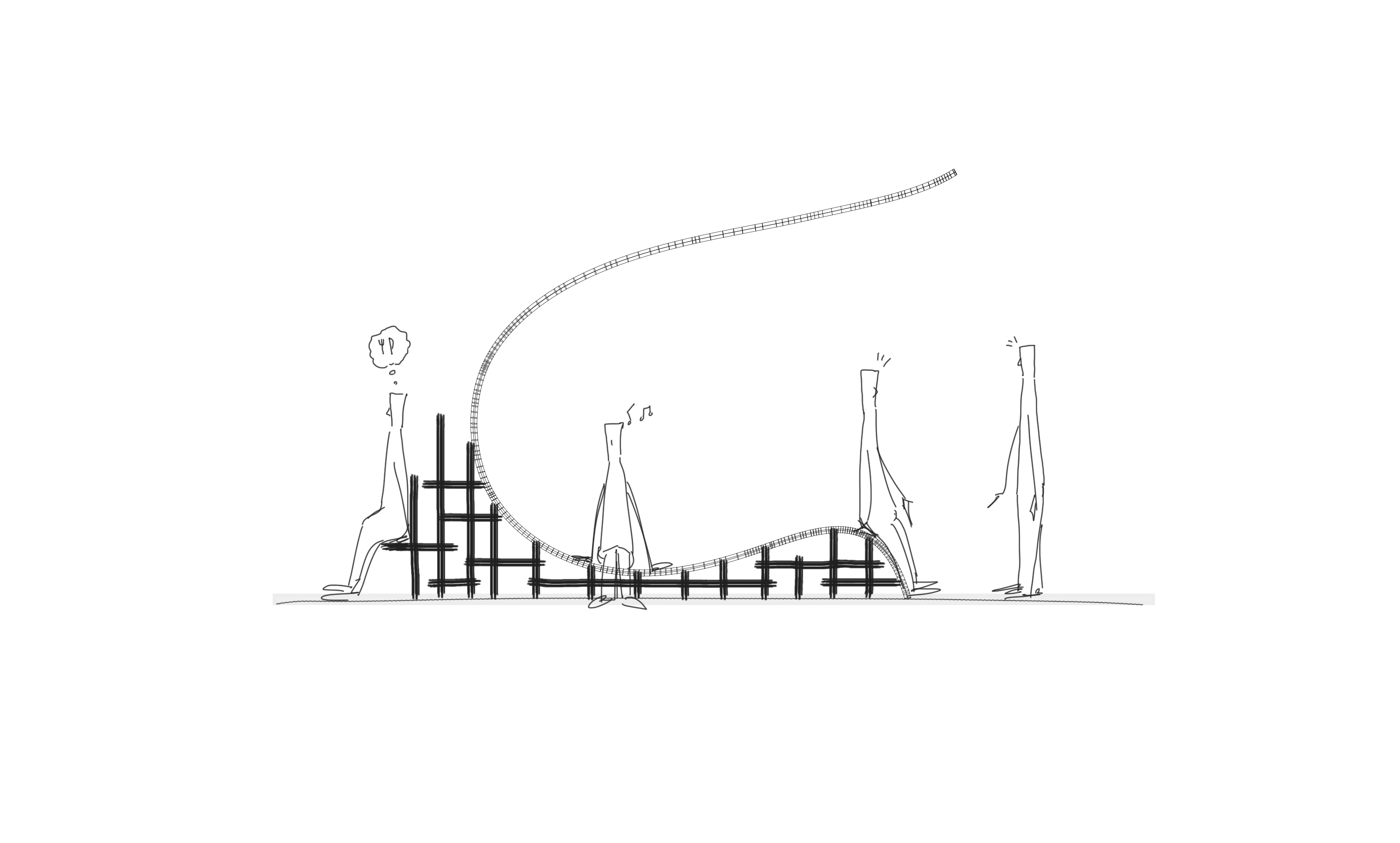
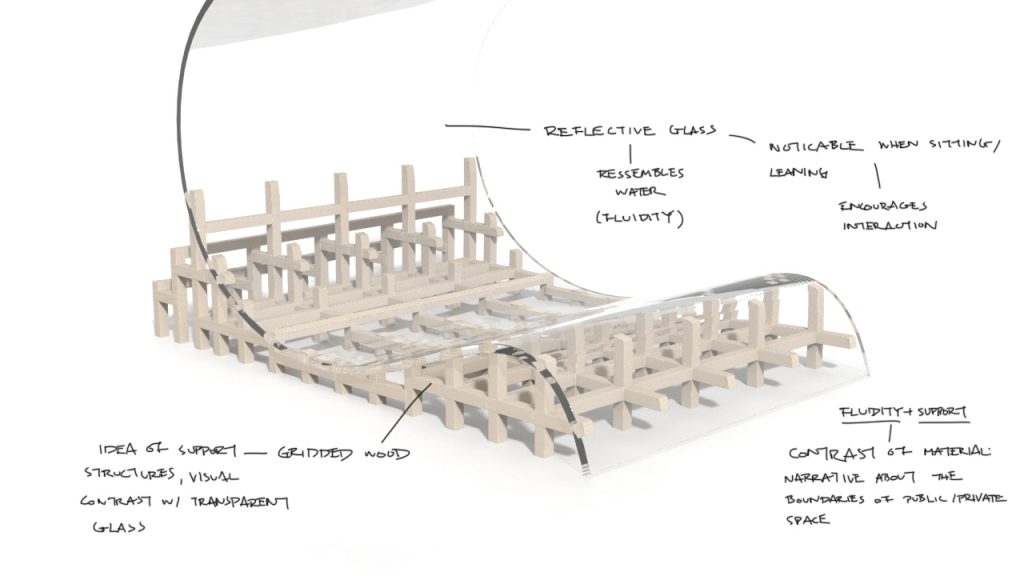
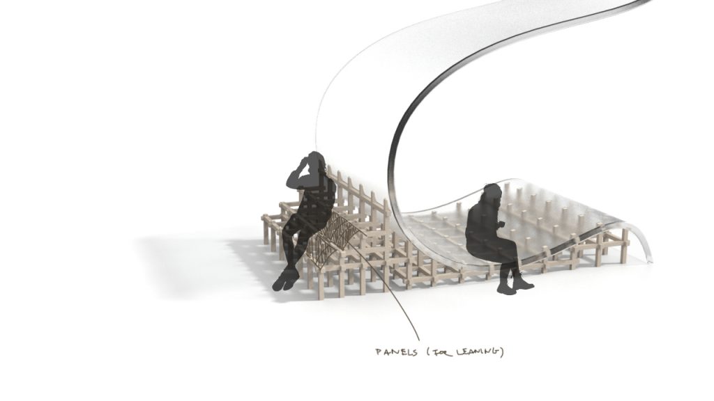
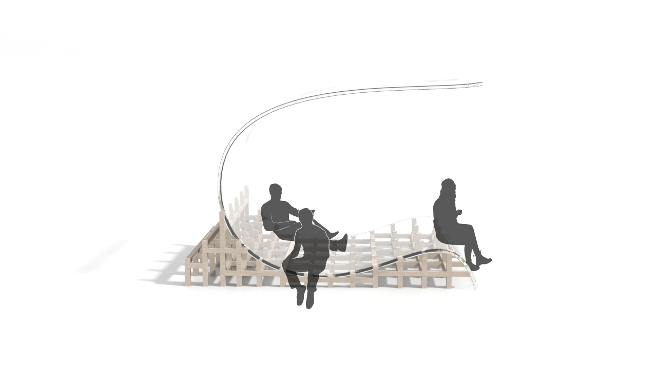
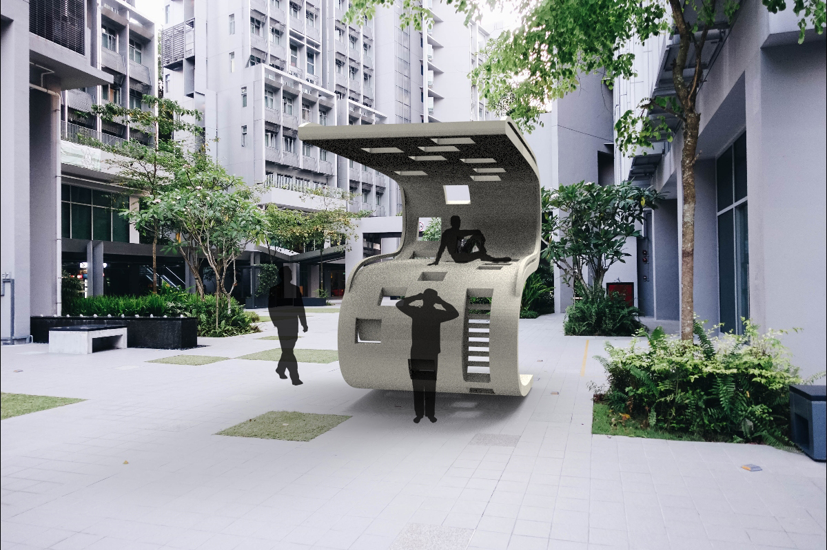
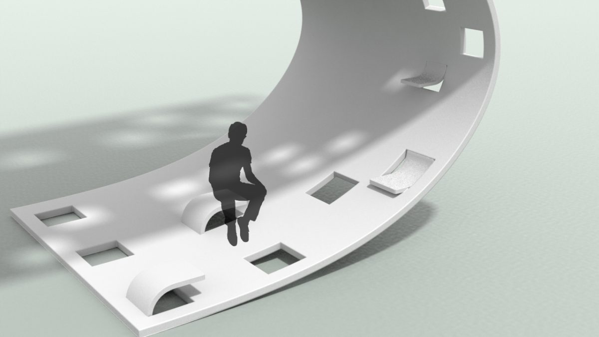
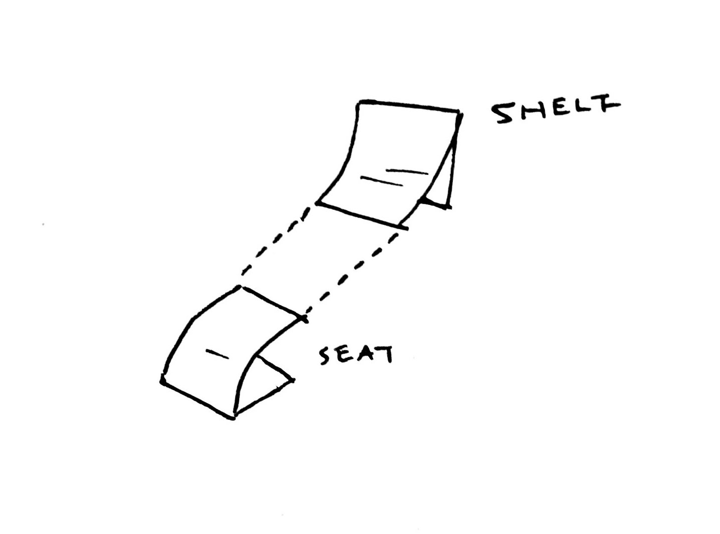
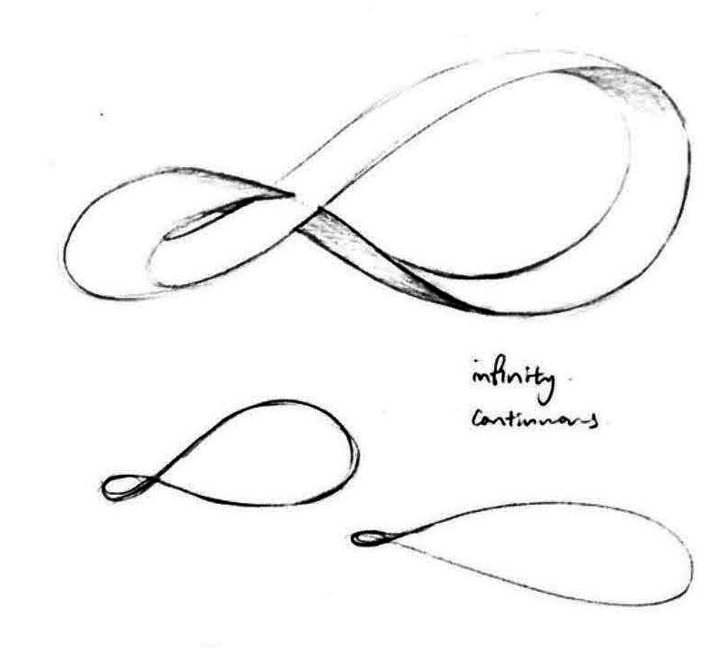
The following illustration depicts our chosen conceptual form and interaction for our installation that is inspired from fluidity and dynamism. The installation aims to provide students of NTU with both personal and public space within a singular sculpture.
Sketch Mock ups
At the beginning, we experimented making the curve with acrylic sheet using a hot air gun. To do so, we made a jig to secure the acrylic in shape.
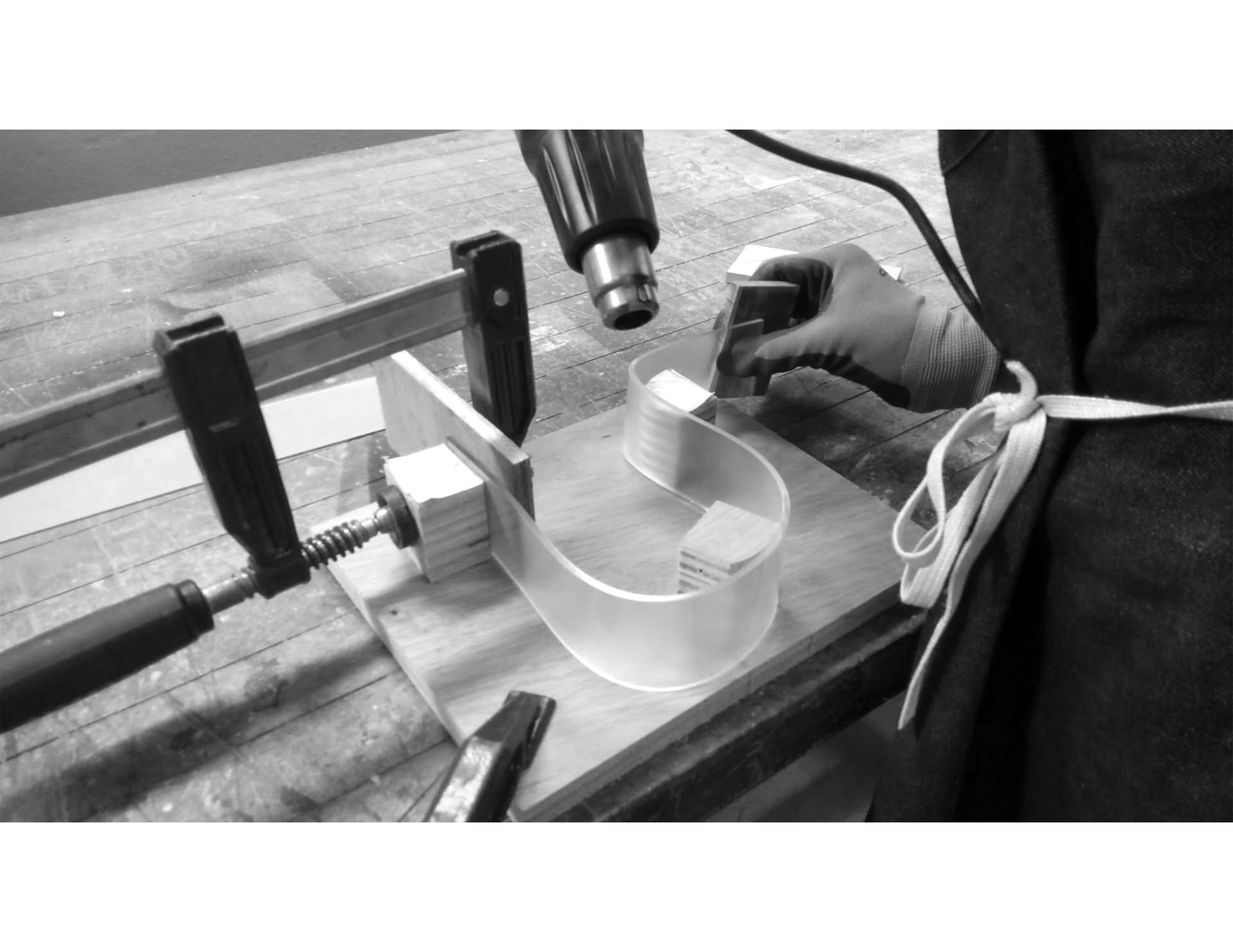
The process was quite tedious. We had to be attentive to the temperature and distance of the hot air gun to make sure we keep a safe distance so that the temperature is not too high. Ultimately, the experiment did not turn out as expected so we have discarded it. We realised that we would need more practice to ensure that the acrylic do not overheat but is heated enough to retain a shape.
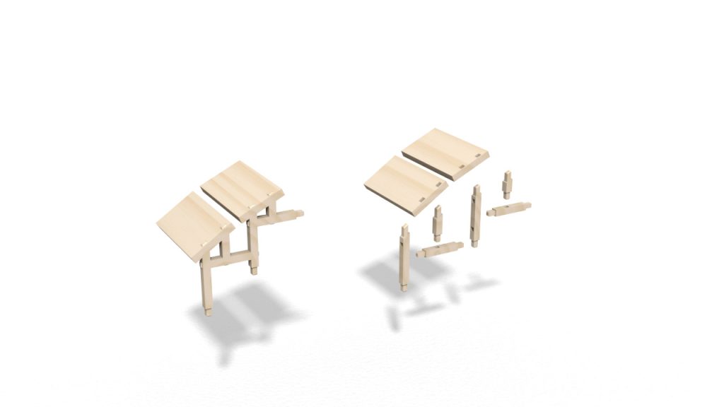
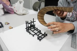
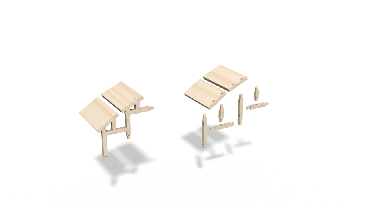
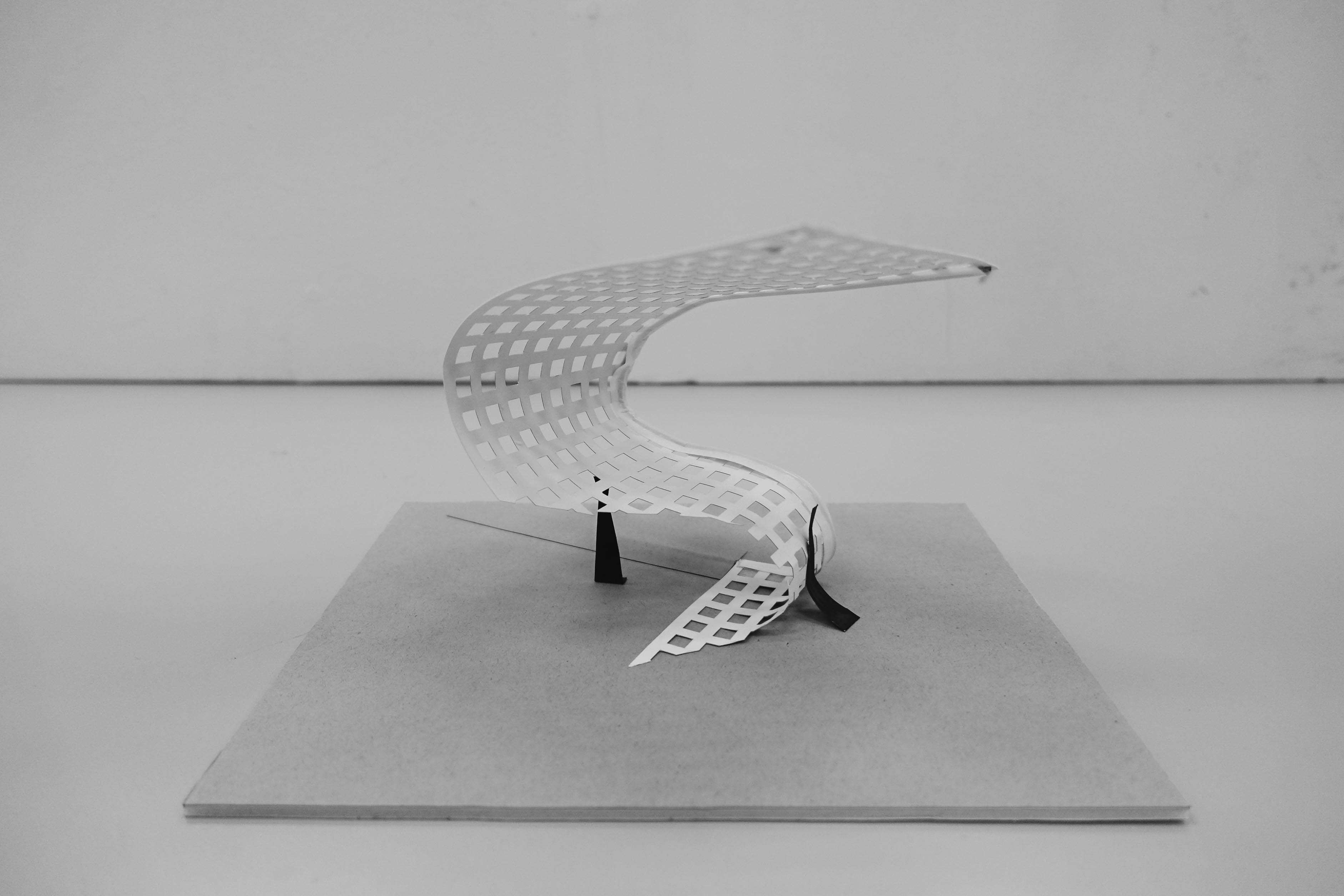
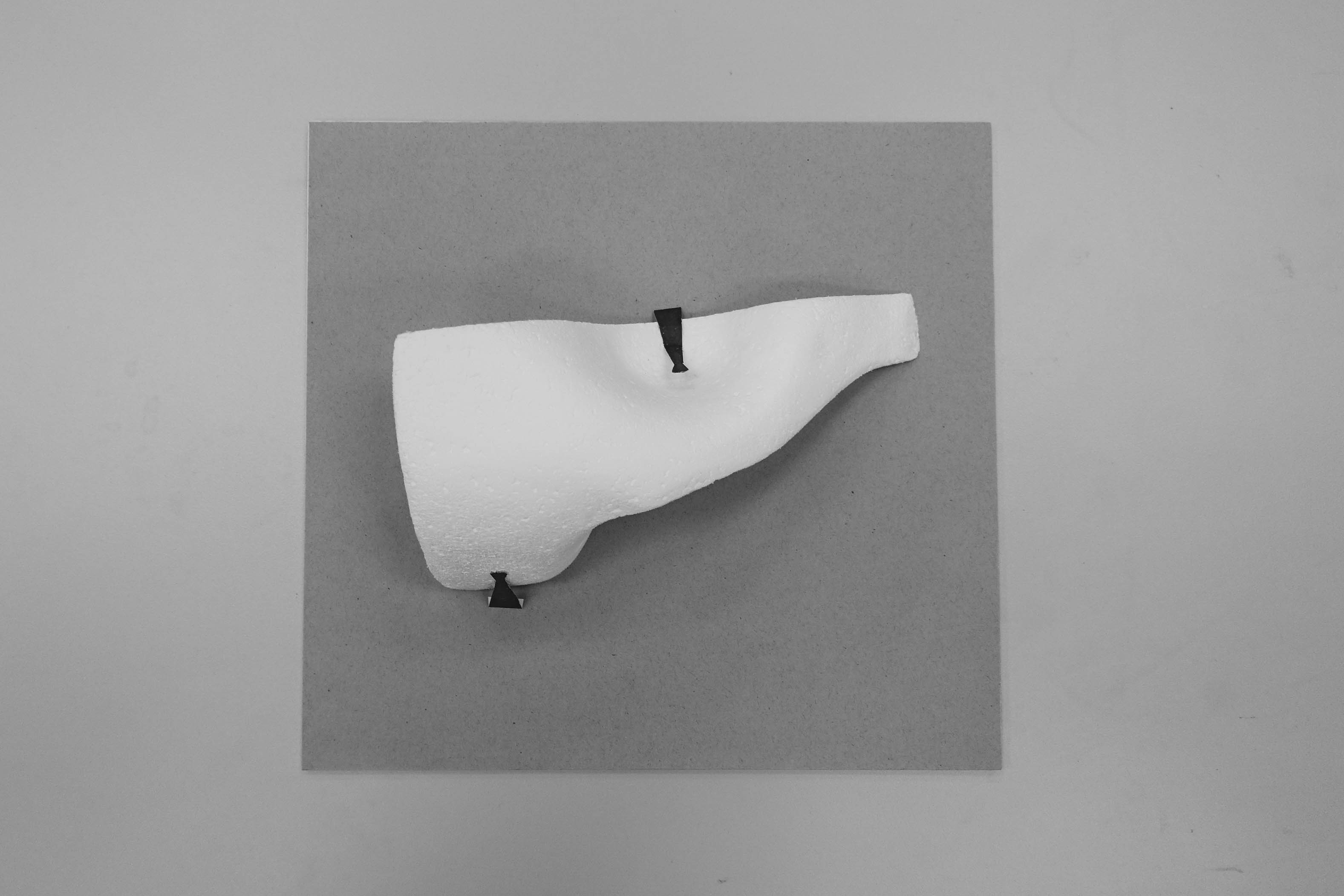
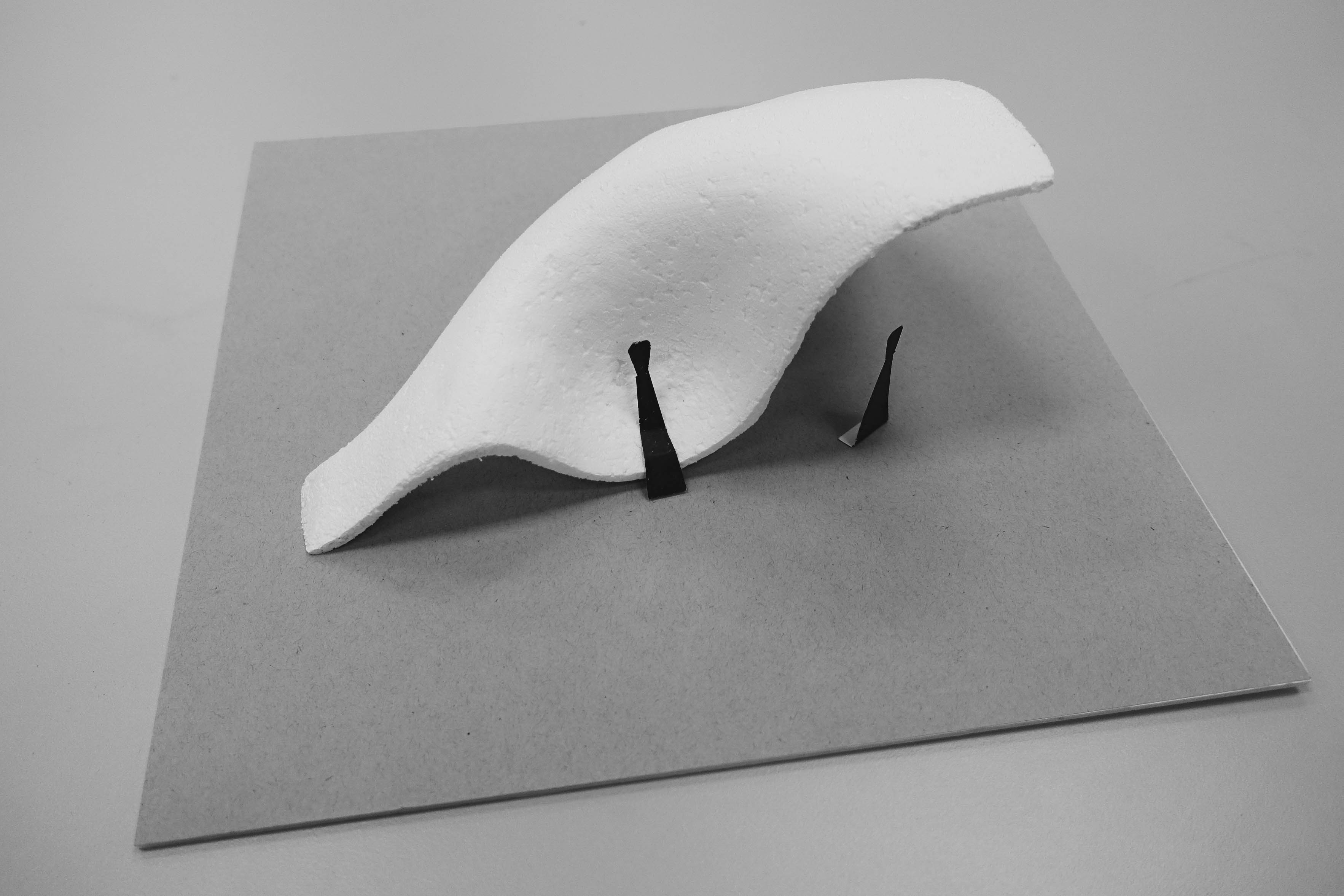
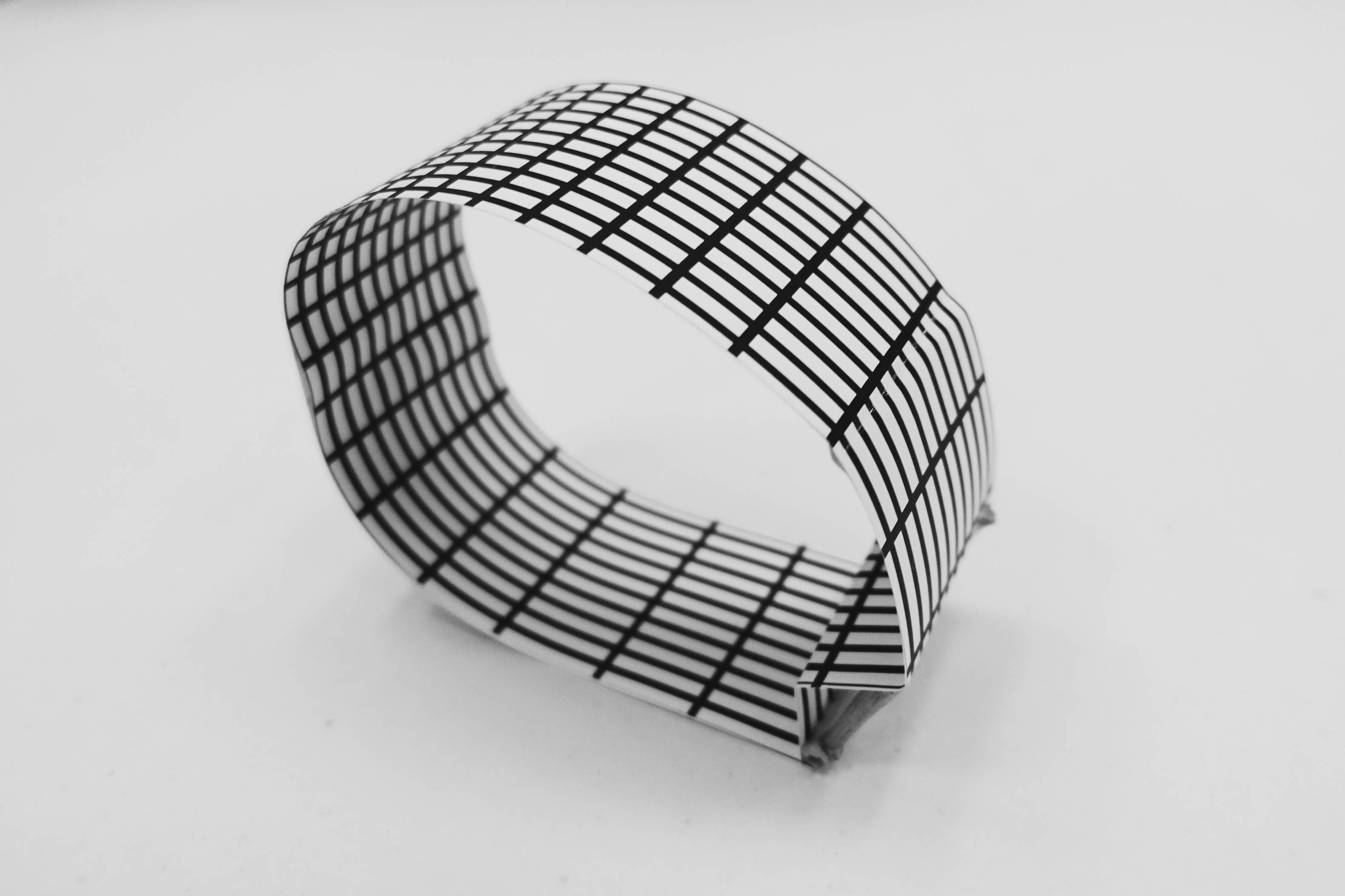
In preparation for the final prototype scaled model, we moved on to working with plywood for a more accurate representation of the installation that we propose to construct with wooden panels. Uploading the dimensions at 1:50 scale, we laser cut numerous repeated panels and two identical cross-sectional profiles.
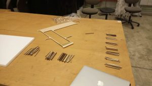

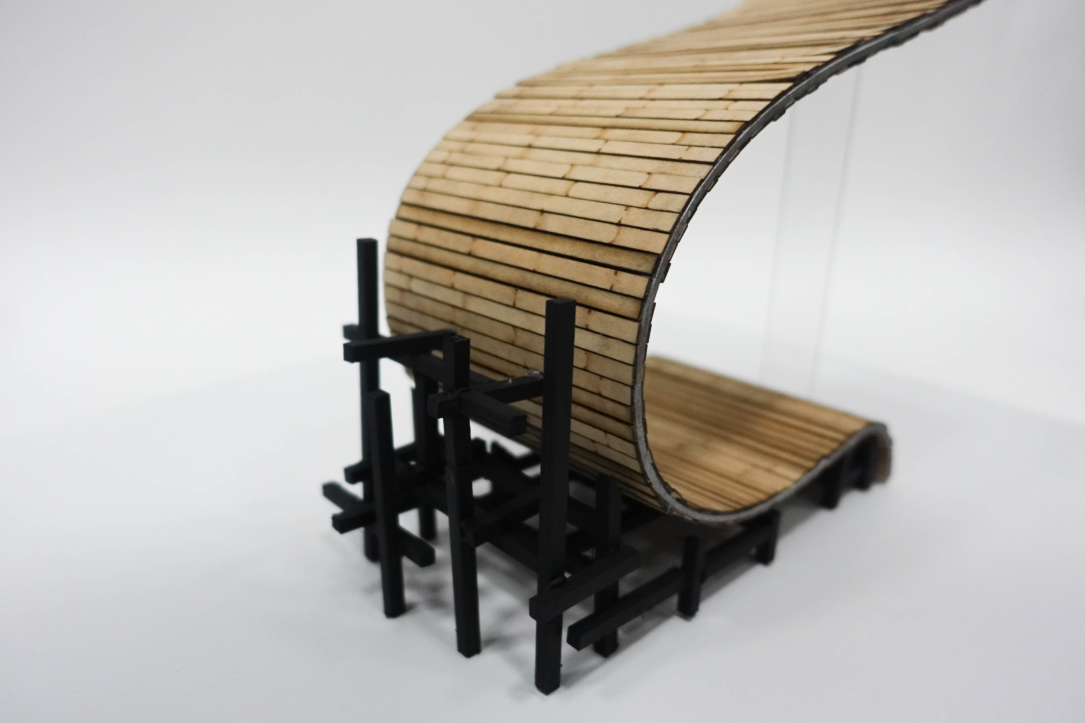
The two identical cross-sectional profiles are spray painted in metallic coating to represent the internal metal support structure. With the help of the bench saw, we made miniature grooves at each end of the laser-cut panels to allow the cross-sectional profiles to slot into the grooves to connect all the panels in a continuous curve.

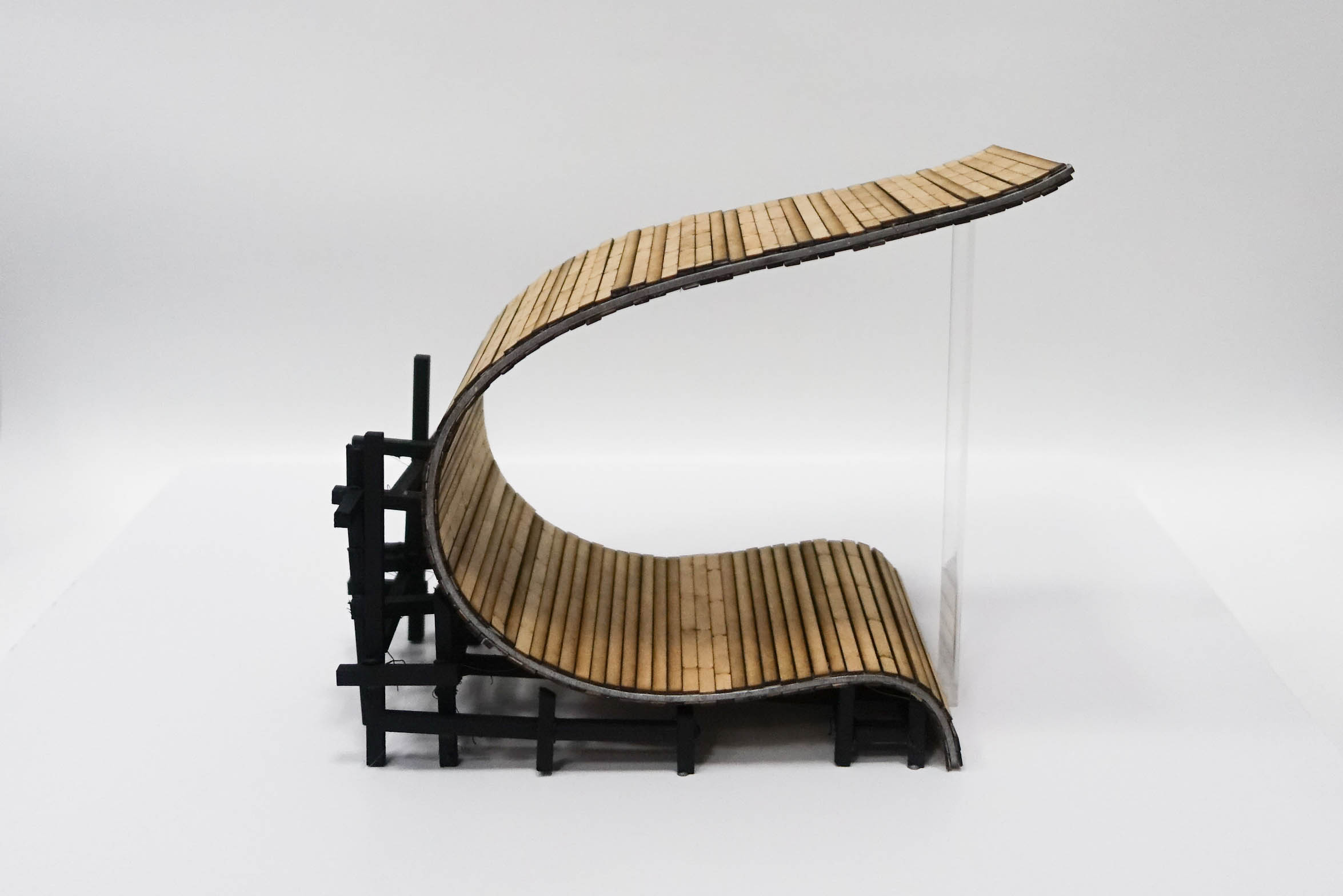
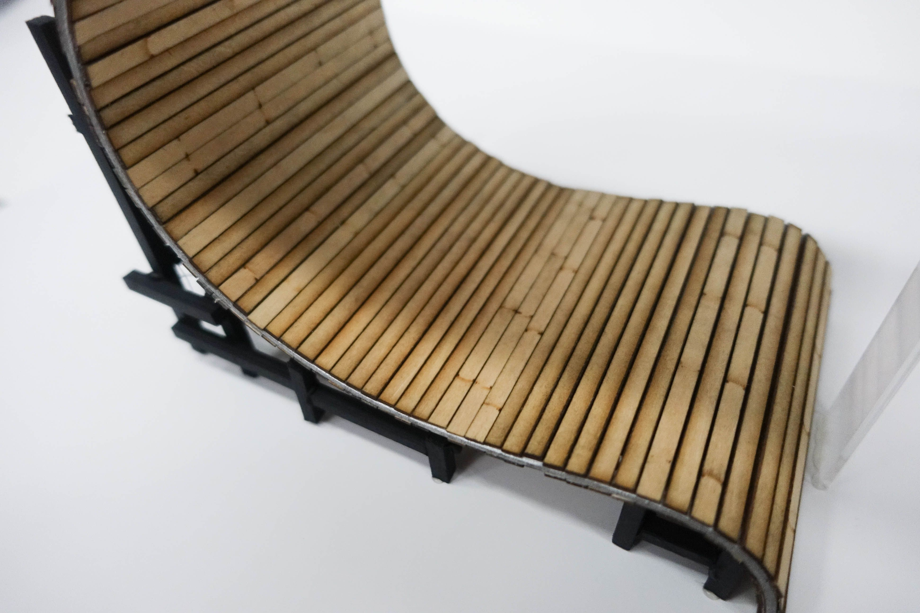

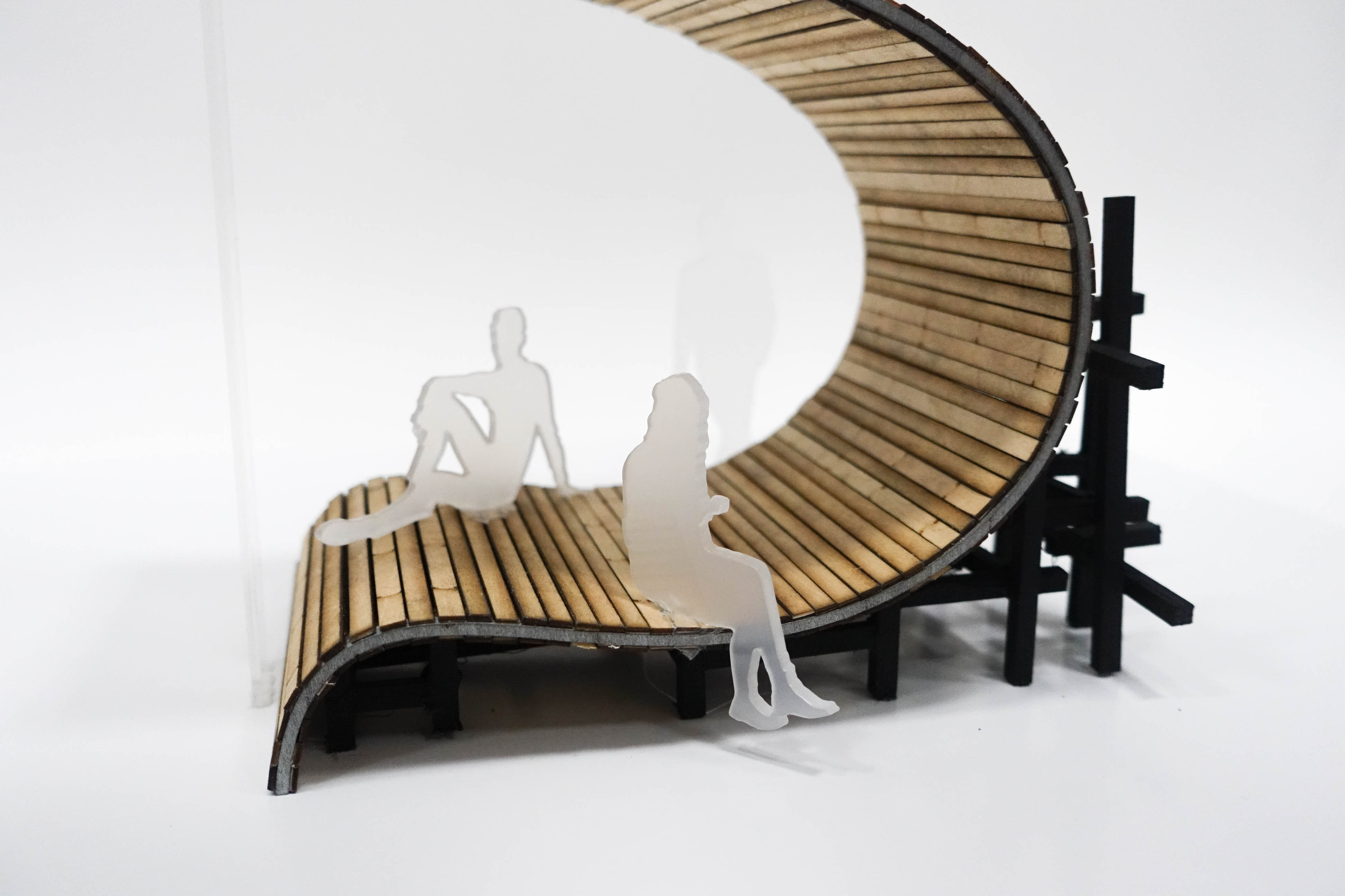
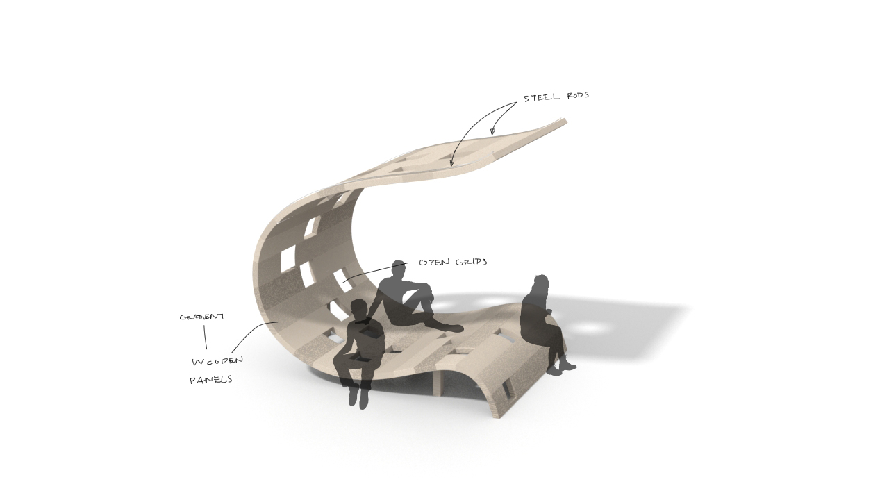
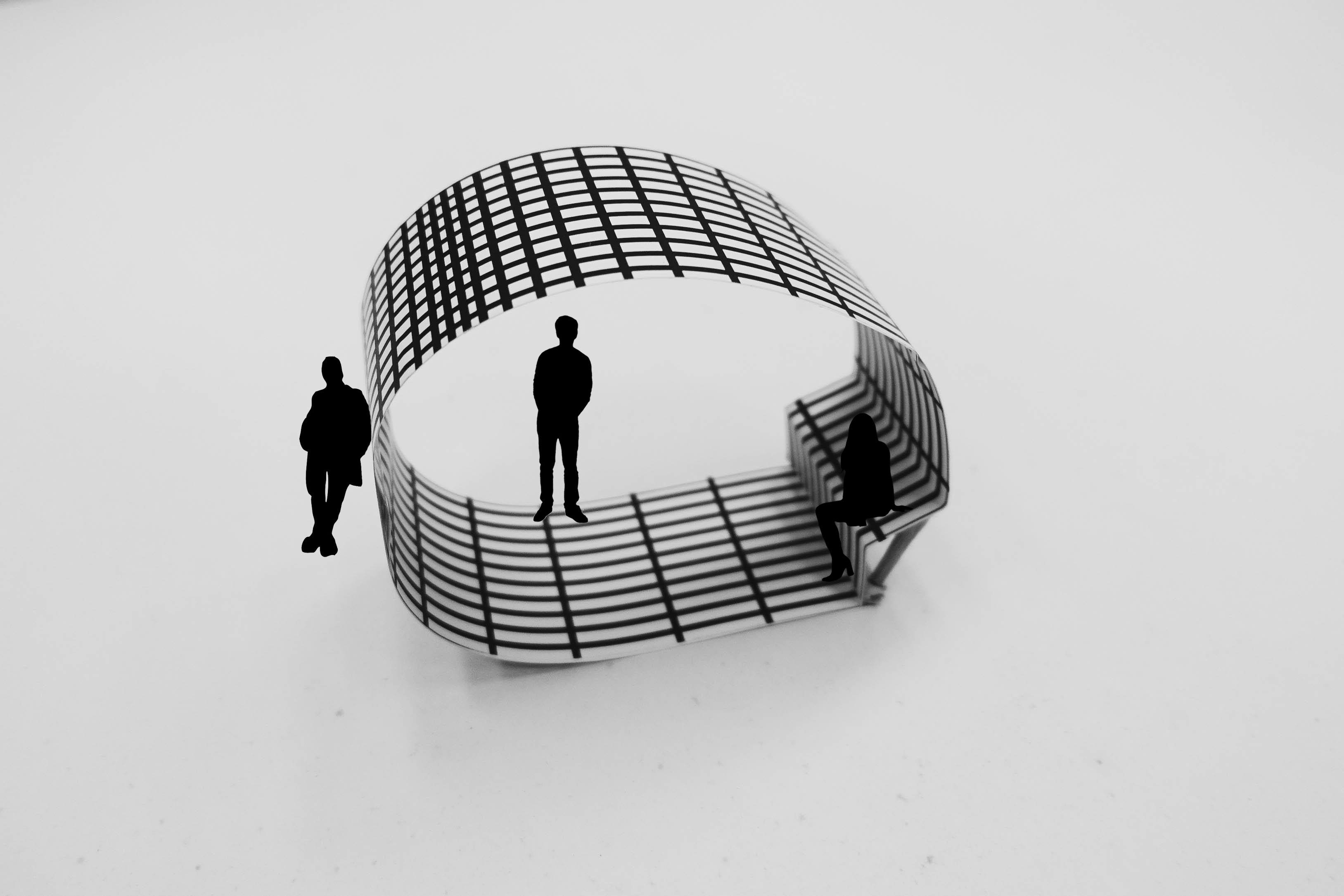
For the virtual 3D model, we have constructed each wooden panels with the dimensions 2500mm long, 120mm in width and 25mm thick. There are a total of 142 panels in total, about 70 panels on the inner wall and 72 panels on the outer wall. A continuous metal rod that serves as the supporting internal structure will be sandwiched between the outer and inner wall of wooden panels.
Click on the image above to watch the installation in movement.
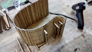
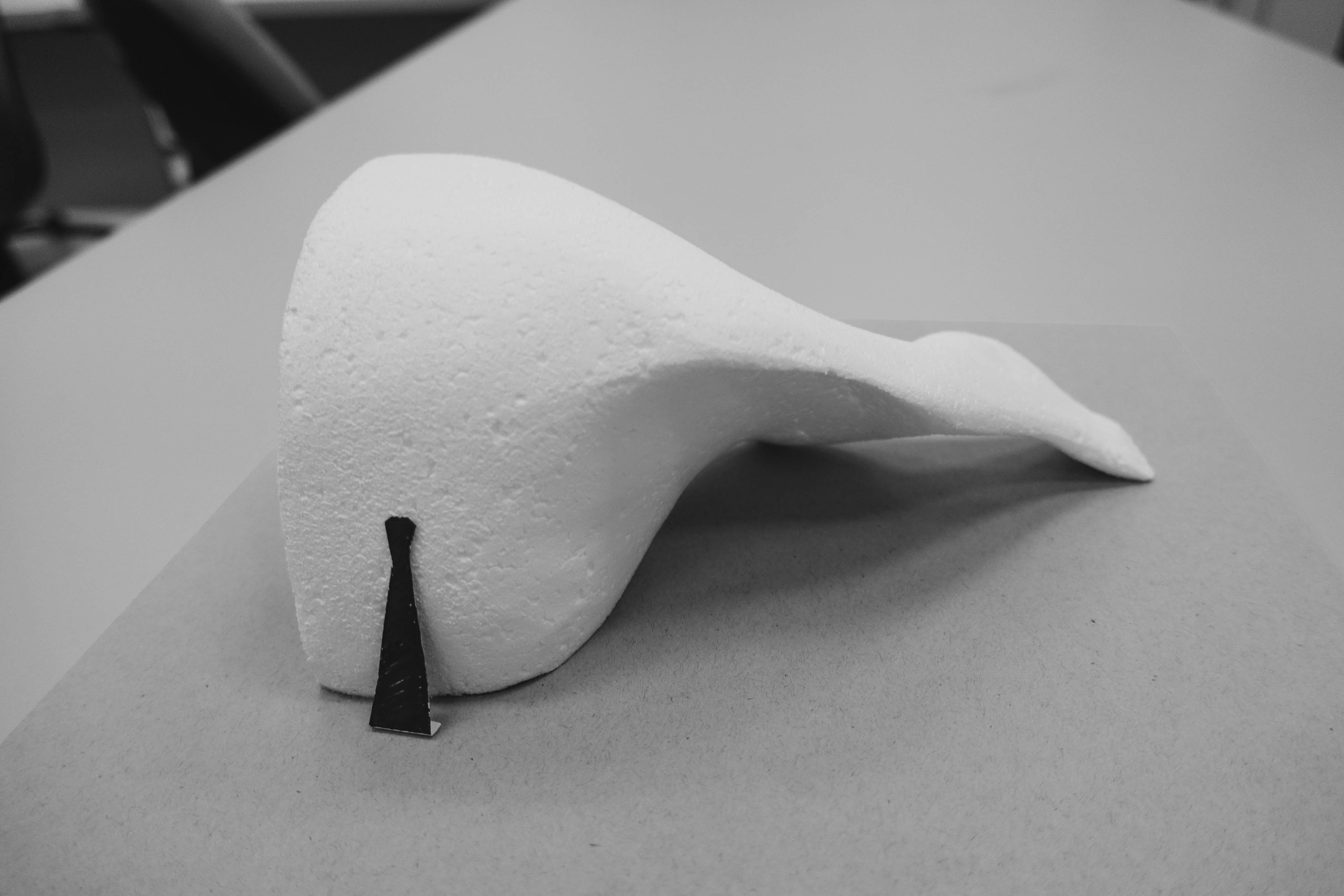
We realised that the weight of the plywood is pretty heavy when arranged along the cross-sectional profile curve that is made similarly out of plywood. To remedy the heaviness of the roof, we have placed a transparent acrylic sheet at the overhang to hold the roof up.
Reflection
During our explorations with making small scale sketch mock ups, we are able to have a better understanding of the different materials to know what are feasible to work with. Through our trial and errors, we are able to have a better plan for the making of our final prototype through improvisations and practice.
Next week
For the following week, we aim to have a final rendition of the installation for a more finalised form with the details included.
Also, we will continue to work on the making of the final prototype model. We thought of using wire to make the cross-sectional profile curves instead of plywood for a stronger internal supporting structure to ensure that the weight of the roof will not alter the shape of the intended curve.
Week 10

Proportion
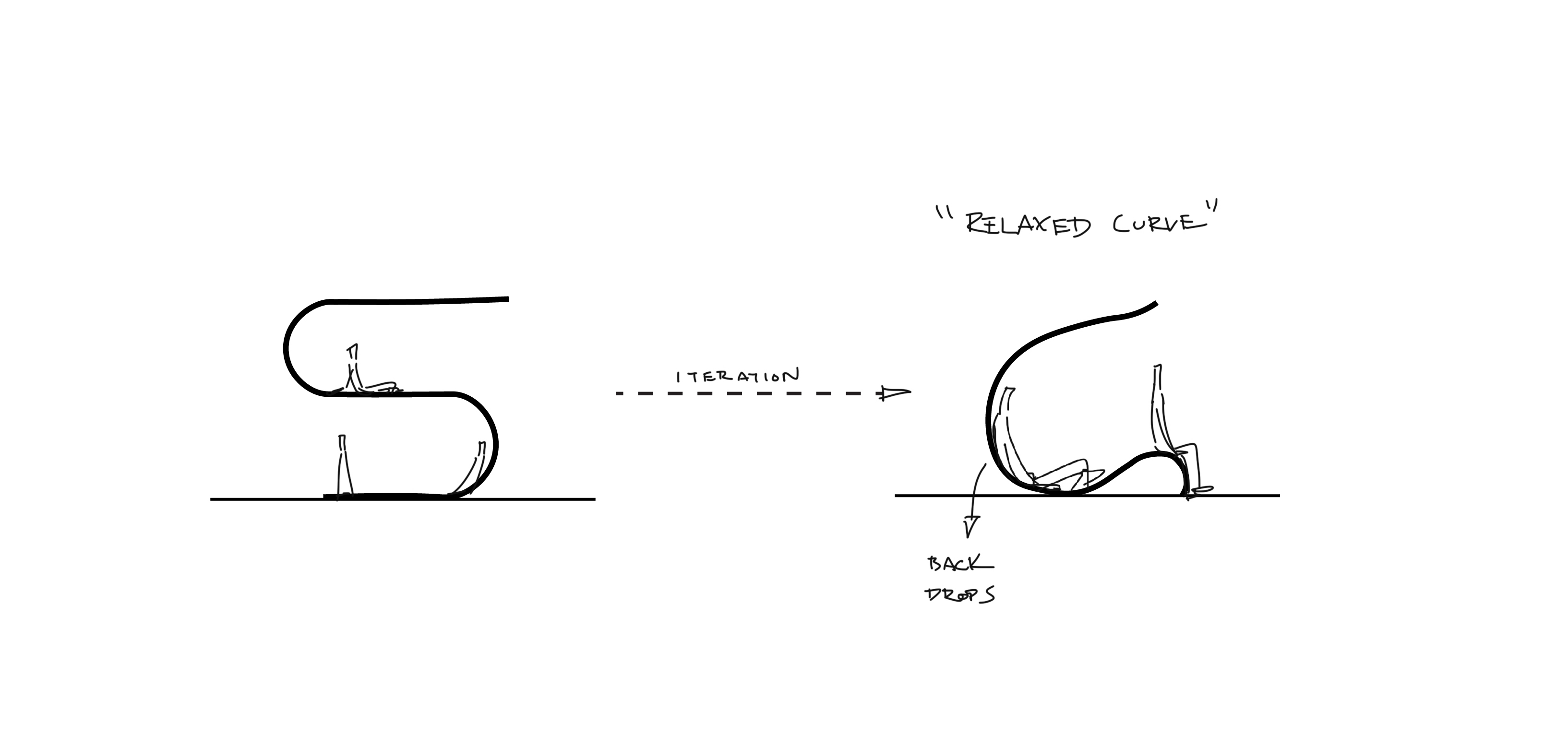
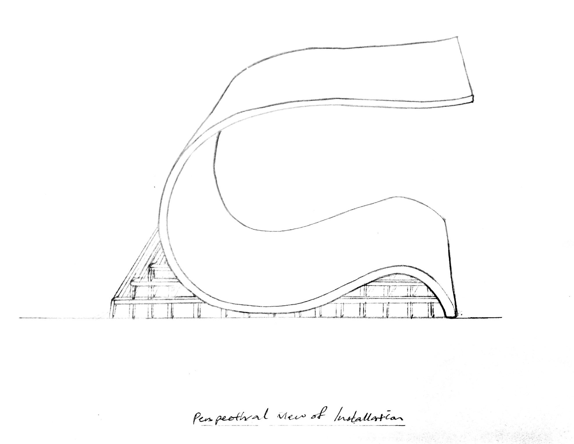
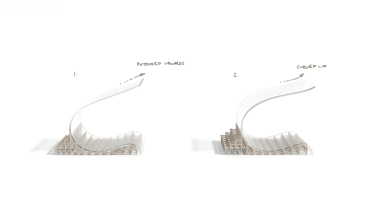
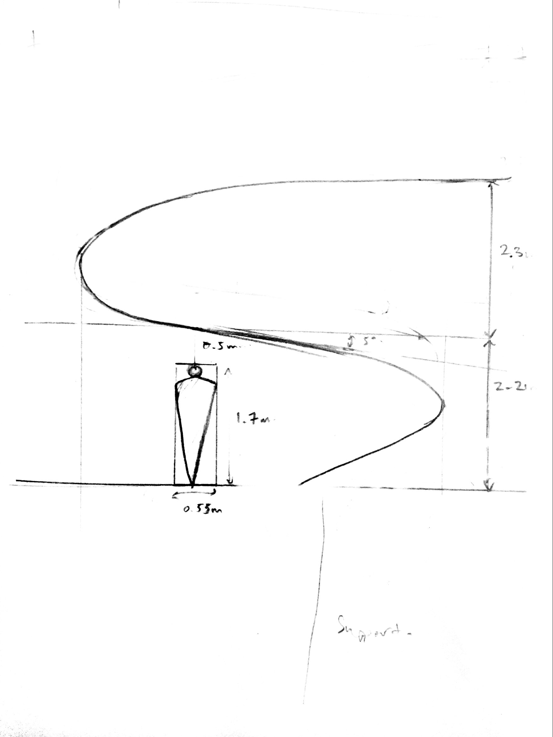
For this week, we decided to re-design and re-proportion the shape of the installation. To inject more dynamism into the shape, we have changed the direction and distance of the curve by increasing the inclination and having an upward progression for the spaces between two surfaces. We can observe that the space between the ground and the first curve in the first direction is smaller than the space between the surface of the first curve and the second curve in the opposing direction.
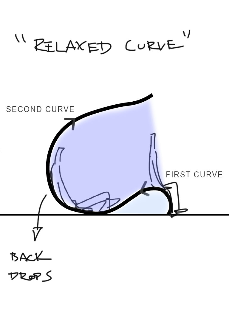
By increasing the space between the second and first curve, the upper part appears elevated and floats above the lower part, reducing the sense of unbalance. By tilting the previous shape backwards and resting the shape at an angle to the ground, the curve appears more relaxed and less static.
Material and sustainability
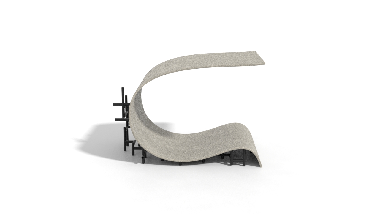


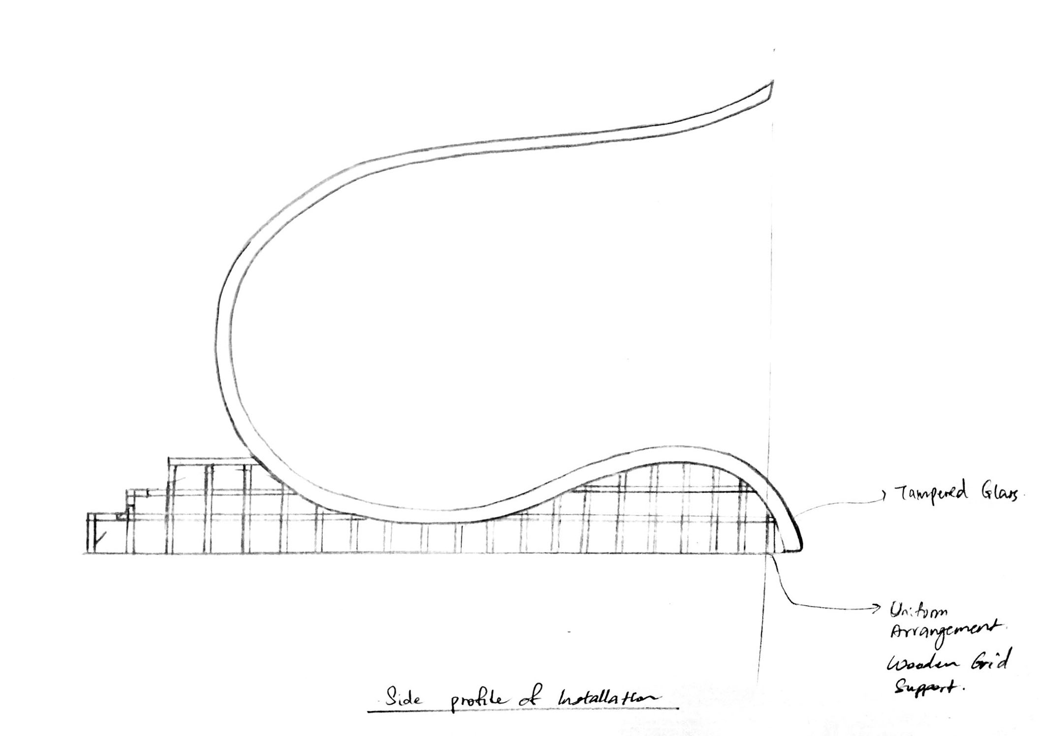
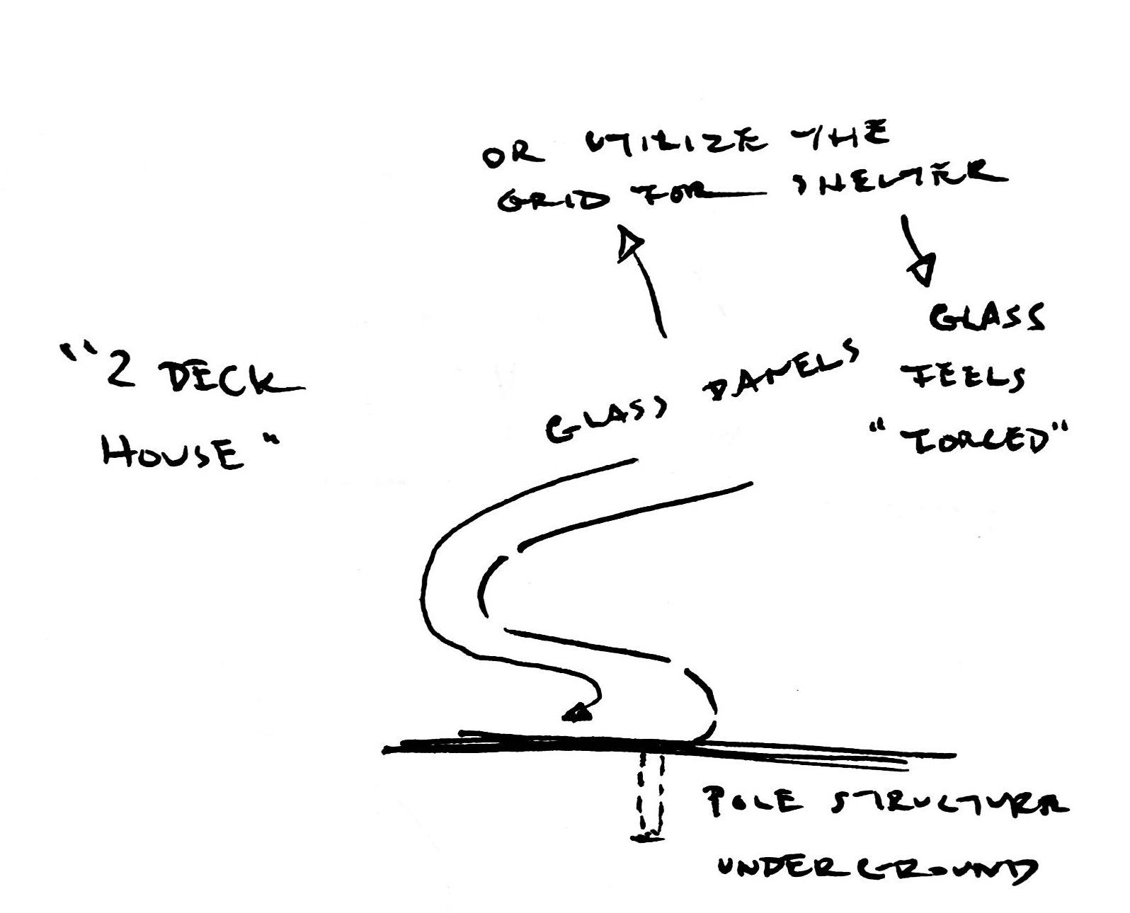
We have incorporated grid supporting structures beneath the curvature for a couple of reasons.
Firstly, the grid serves as a pedestal to elevate the curvature.
Secondly, the grid serves as a elevation above the ground by approximately 350 mm so that users can sit comfortably on the curvature at that height.
Thirdly, the grid serves as a contrasting element. Juxtaposed with a rigid and uniform grid, the curvature appears to be fluid and dynamic.
In order to understand what translucent material would be best suited for construction that is safe and strong, we did a research into the different types of glass and properties of thermoplastic that projects an appearance like glass.
Properties of thermoplastic
Polycarbonate: This plastic is 300 times stronger than glass, is resistant to most chemicals, is twice as lighter than glass, has high abrasion and impact resistance. It can transmit as much light as glass without many distortions. Applications include window, green house glazing etc.
Adapted from Glass as a Building Material. (n.d.). Retrieved March 25, 2018, from http://www.understandconstruction.com/glass.html
We would like to propose using semi-transparent polycarbonate for the construction material of the installation as its transparent property is closest to fluid.
Polycarbonate has been said to have a lifespan of at least 10 years and can be recycled.
Other than the choice of polycarbonate, we also propose using GFRC concrete or wood for the construction of the installation. GFRC is a sustainable material and has a longer lifespan than polycarbonate. Wood would be a more affordable choice of material. It is also a material that is versatile and exude a warm shade (as compared to metal) which makes it a more inviting material.
Aesthetic and function
The new shapes does not require any rails and ladder since it no longer have a second level. Although we have altered the presentation of the shape, we still retain the concept of a personal and public space within a single sculpture.
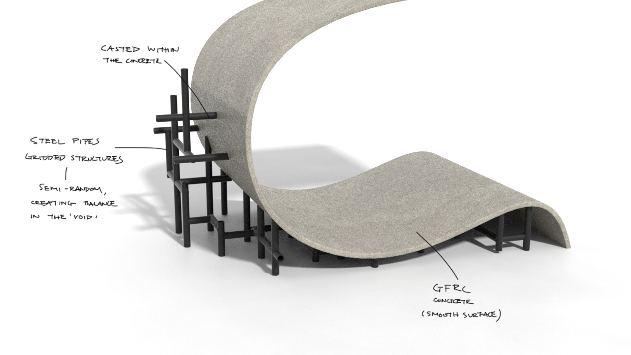
For the Concrete model, the metal rods are organised in random order like the random arrangement of square holes represented in last week’s model to complement the dynamic flow of the curve.
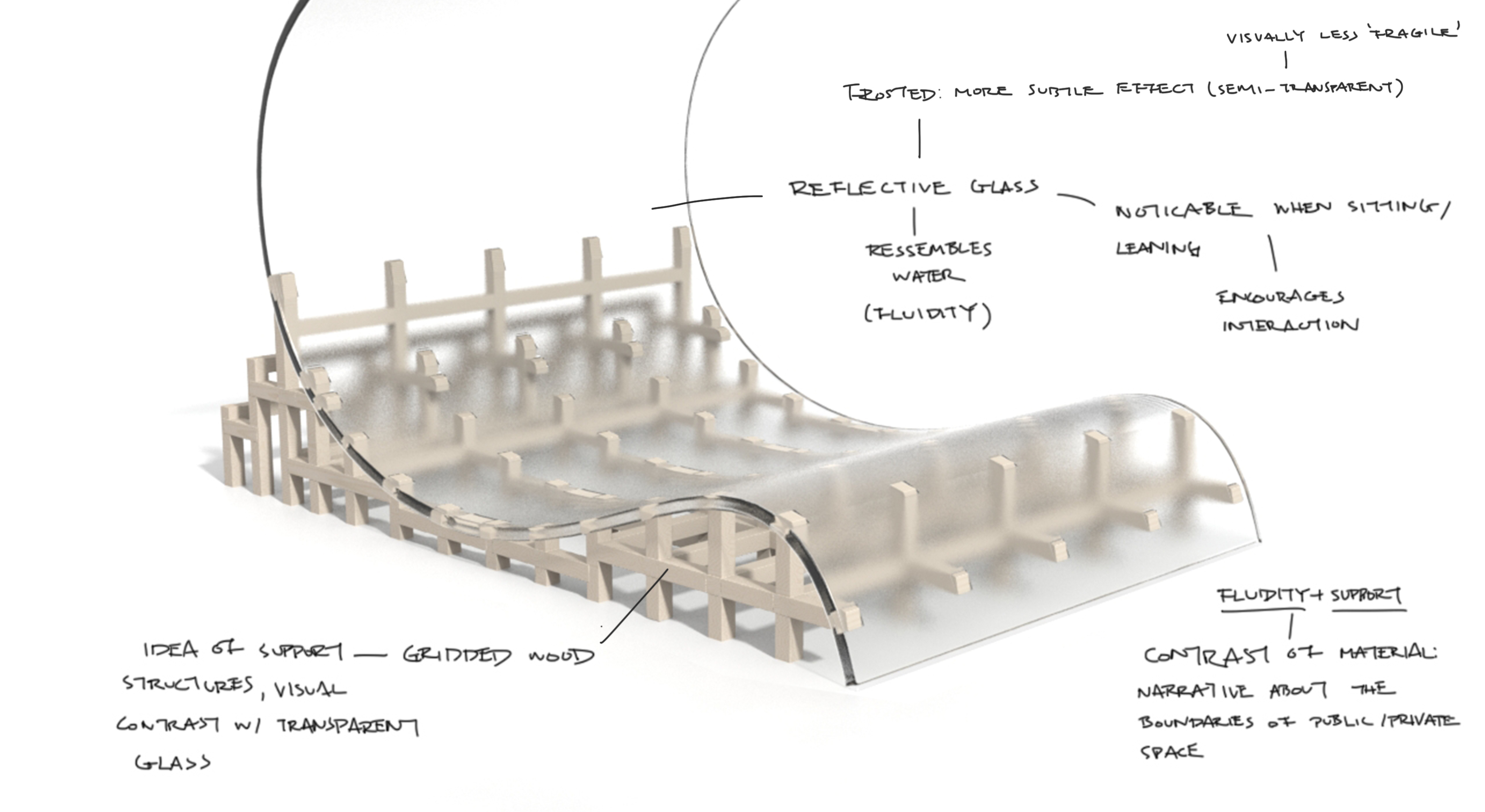
Whereas, for the polycarbonate model, the wooden rods appears more organised than the metal rods in the concrete model. This is to create a contrast between the dynamic curve and static grids.

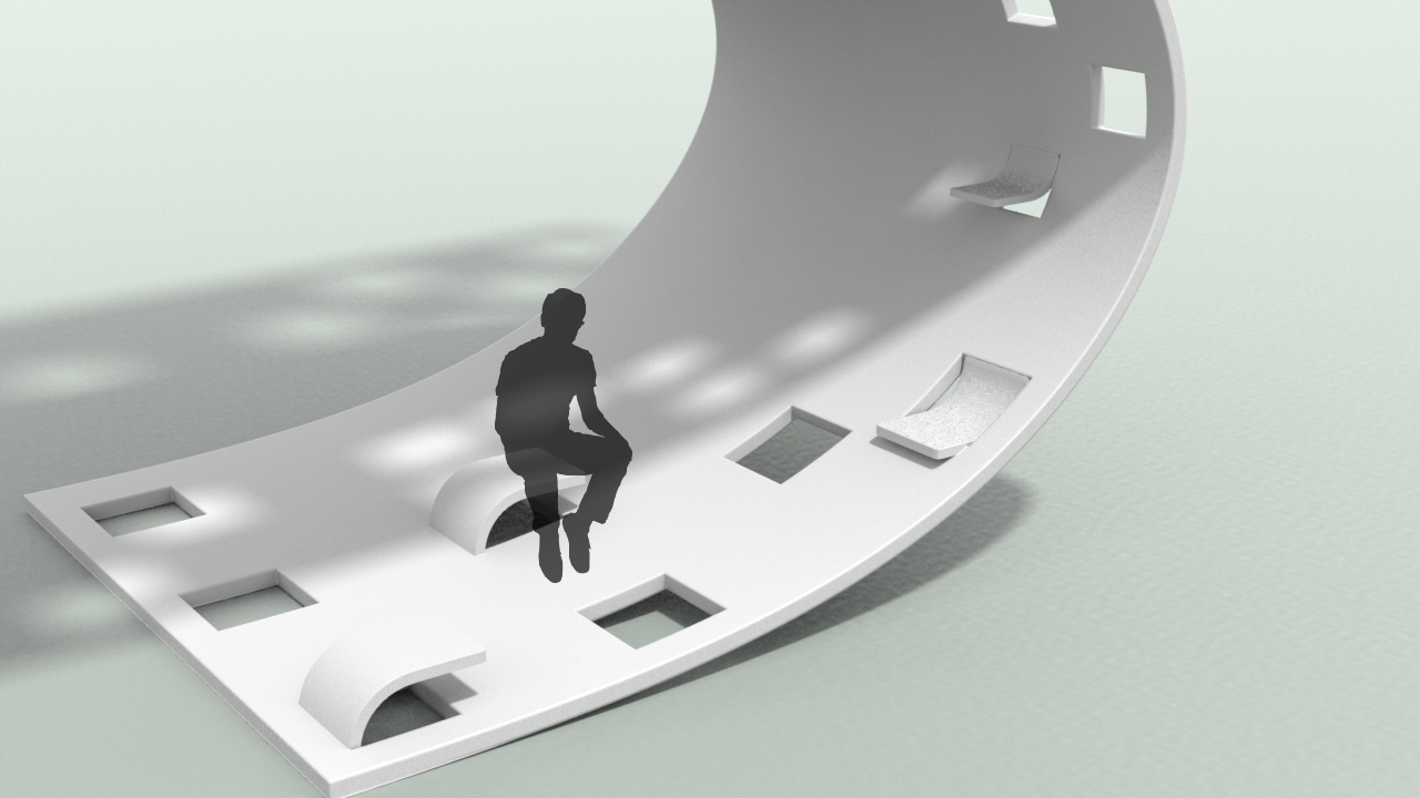
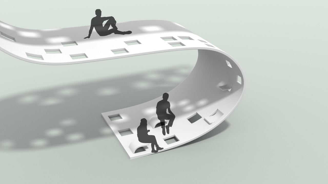
Dynamism
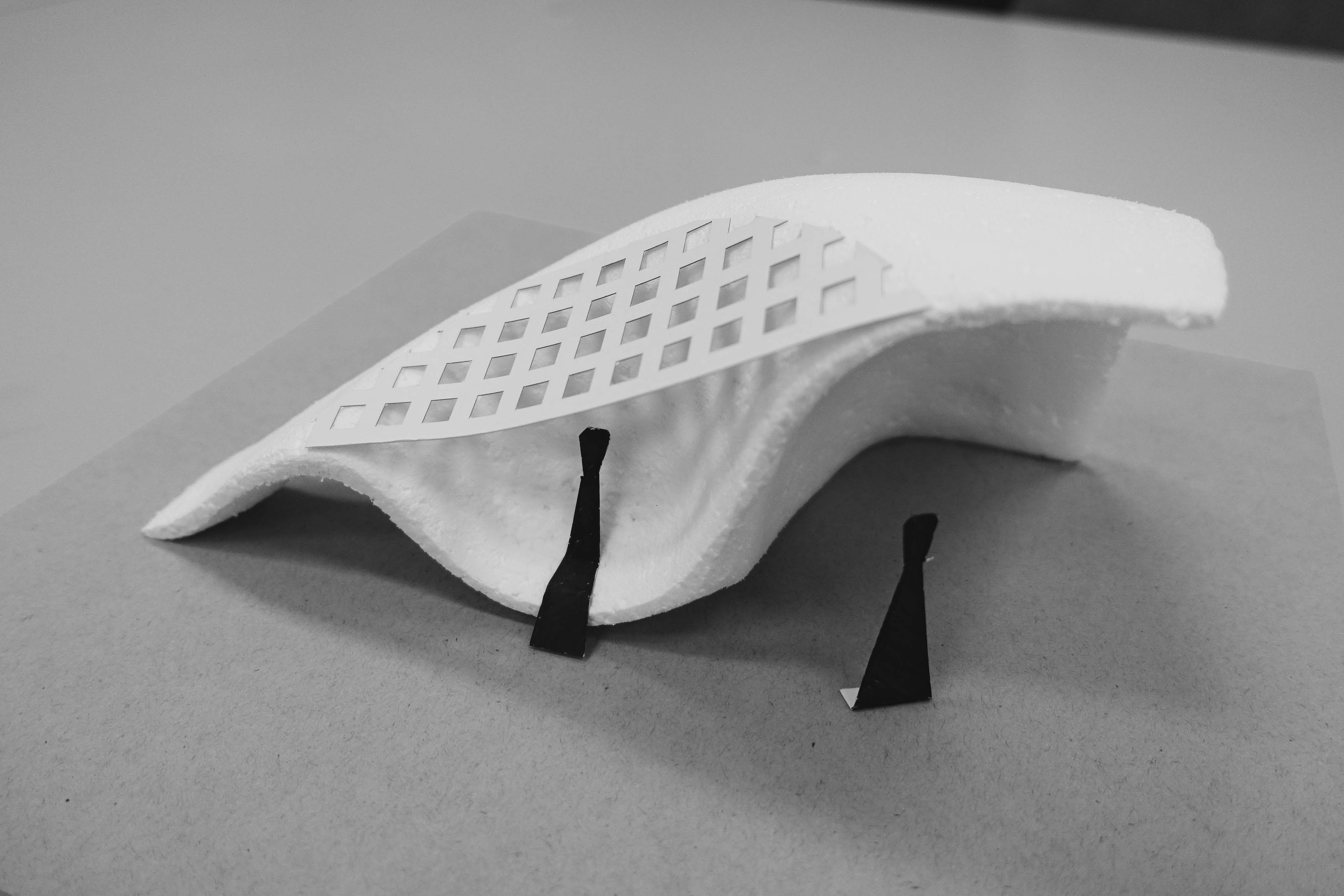
Other than a polycarbonate sheet, we continued to explore with grid patterns on the curved sheet. We rearranged the square holes in hierarchical progression to convey dynamism. In terms of construction, we would like to portray the square holes with wooden panels that are connected with metal bolts and supporting frame.
If the installation with patterned surface appeals more to people, we plan to research deeper into the arrangements of square holes in the curvature such as by following a certain mathematical progression or a pattern derived from an abstract representation of the location (eg. ariel view of grass patch at location/ arrangement of windows of buildings at location).
Week 9

Further development on Form and Function of Installation
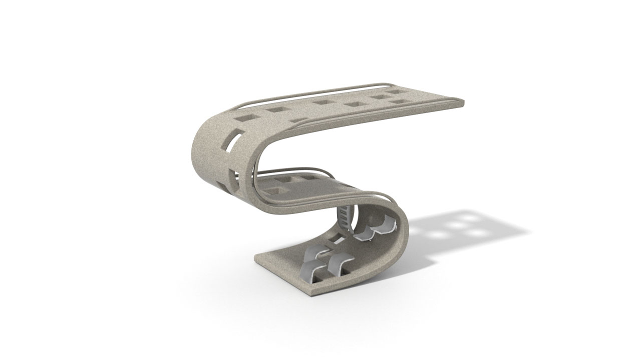
New developments such as the addition of a curved seating, curved shelves, curved ladder and safety railings have been updated in the most recent rendering of our installation. We have also refined on the proportions of the sculptural installation in the renderings for a more accurate depiction of the real thing.


Users are able to sit at the lower deck of the installation on curved seats (extruded metal surfaces) and utilise the curved shelves to place small objects such as water bottle, hand bag, phone, notebook, etc. Users can climb up to the second deck with the help of a curved ladder and sit on the surface of the second deck.
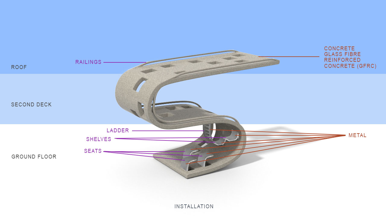
As we are looking at the majority of people in NTU, who are aged above 18, we believe that users would be mindful and rational enough to practice the necessary cautions when interacting with the second deck and roof of the installation (Approximately 3.07 metres in total height) . We have included a 15 centimetres high and 5 centimetres wide railing along the edge of the installation, as a reminder for safety and caution practices. Although the roof is intended to be restricted from access, we predicted that playful individuals may try to access the roof by climbing on the grids, thus we have also incorporated railings on the roof.
We have included an image of the previous rendering for comparison below.

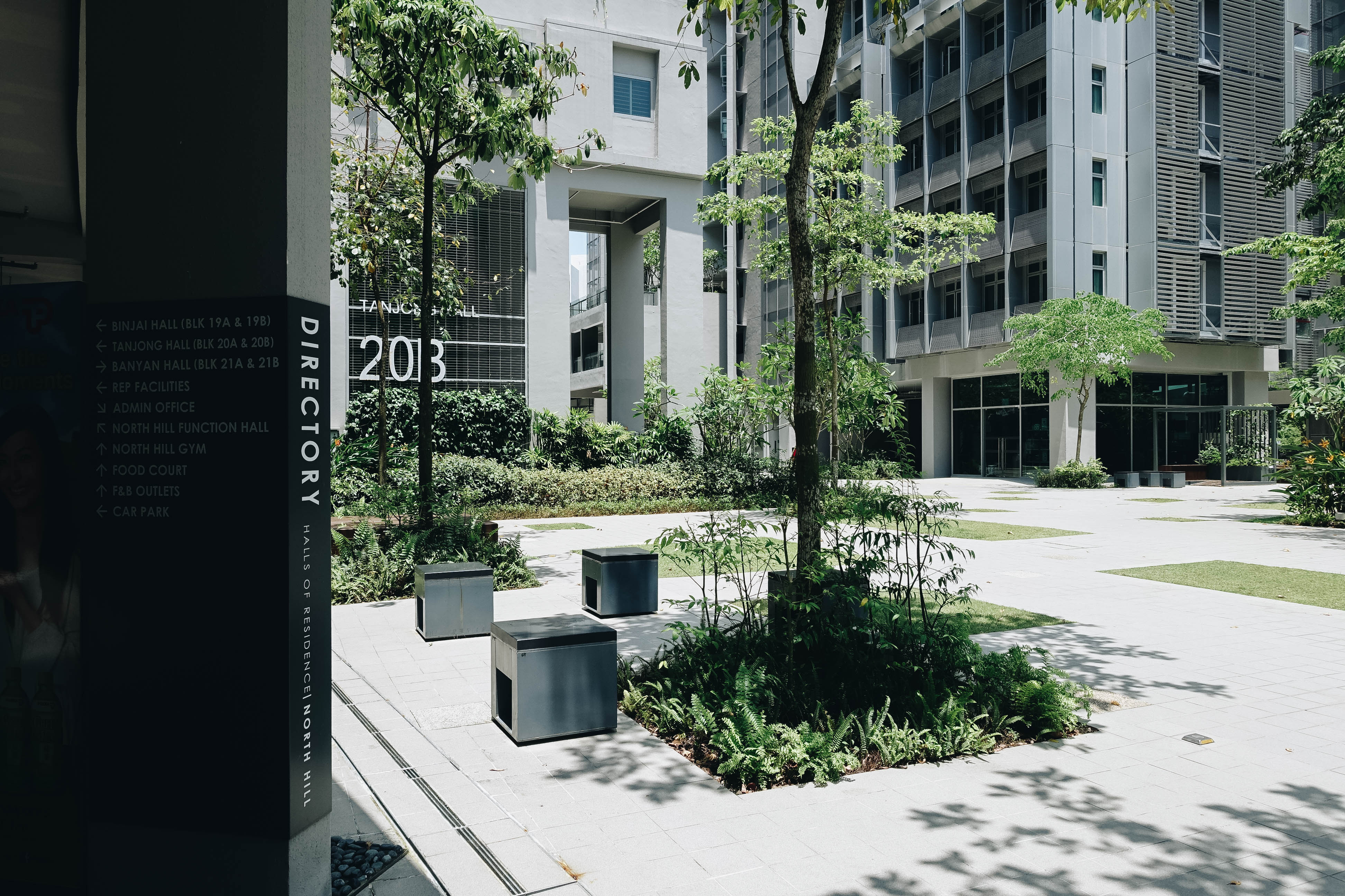
Environment for installation
Our intention for our installation is to provide people in NTU with both public and private space within a singular physical structure.
Our initial intention was to position our installation within a natural environment in NTU so that people can have the opportunity to rest under the shade of the installation and experience the beauty of nature. However, after much thought, we find that the installation would match the environment of Banyan Hall at NTU better as Banyan Hall has many gridded and randomly arranged square motifs for its tiles and green spaces which echoes the random gridded pattern of the installation. We have decided to reconsider the placement of the installation in NTU and focus our direction on having the installation possibly placed at Banyan Hall.
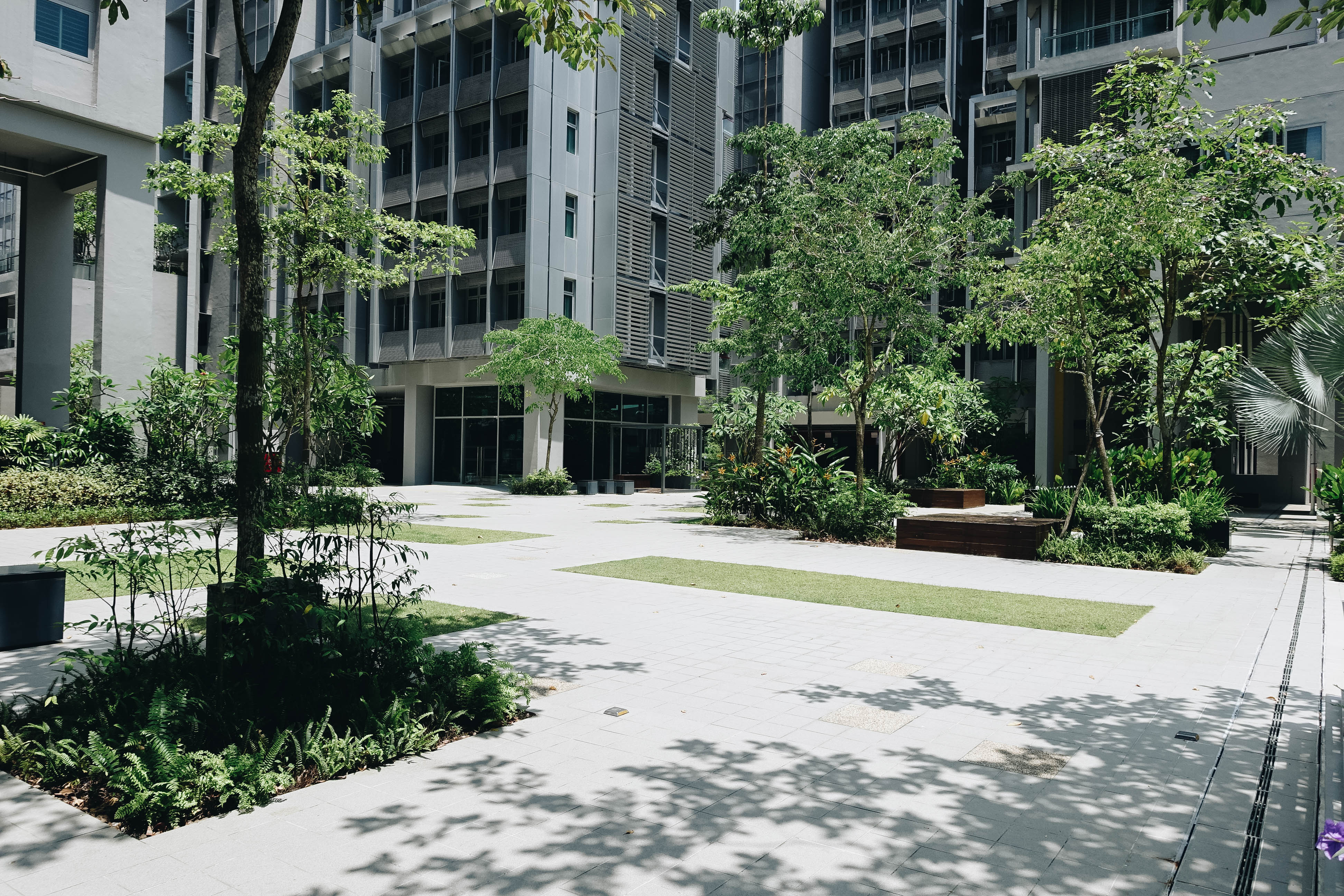
We hope that by incorporating the installation in Banyan Hall, non-residents and residents of Banyan Hall can come together to meet under a shared roof or find a personal space within the installation.
Junya Ishigami

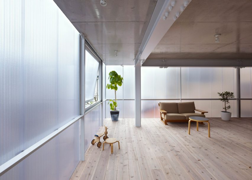
We have looked at Junya Ishigami’s Project for the cafeteria on the campus of the Kanagawa Institute of Technology as a study for how to abstract and integrate a location and time period into a new type of hybrid space that could not have been conceived either by contemporary architecture or classical architecture alone.
Possibly, we may research more into Junya Ishigami for a reference.
You may read up more on the project here.
Selected Material
We intend for the installation to be constructed out of Glass Fibre Reinforced Concrete GFRC. To understand the sustainable uses of the building material, we researched into it.
GFRC as a Sustainable building material
Ingredients: natural ingredients uses recycled materials, including glass and metal with low toxicity levels have no adverse effect on the environment or ecosystems within the environment
Minimal Natural Resources: GFRC uses less cement than traditional concrete does. Ingredients used are naturally occurring and sustainable.
Manufacturing Process: Producing this water-based building material does not emit any chemicals or byproducts that would harm the environment.
Construction Process: GFRC contains fewer natural resources, uses locally available materials, reduces energy use, fuel consumption, and transportation resources. It’s lightweight property means that less material is required.
Low Waste: GFRC produces less waste than traditional concrete
Building Life: GFRC is durable and long lasting so that it can withstand hurricanes, weather, fire and seismic activity, this reduces the need for maintenance, repair, and replacement, which means lower emissions and disruption to the natural environment. A long lasting building also means that it does not require maintenance or repair, saving energy and natural resources in the process.
Highly Sustainable GFRC. (2014, August 04). Retrieved March 19, 2018, from https://www.gfrcinfo.com/highly-sustainable-gfrc/
Recess Week – Study into the Seville Roof
Study into the Seville Roof
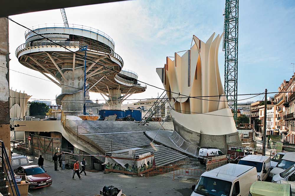
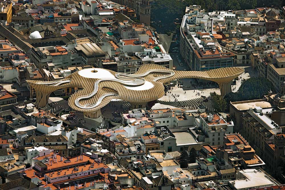
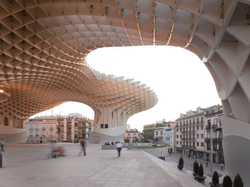
To begin, we would like to cite DETAIL inspiration on the webpage titled Technology: Metropol Parasol – a Stroll Above the Roofs of Seville written by Frank Kaltenbach.
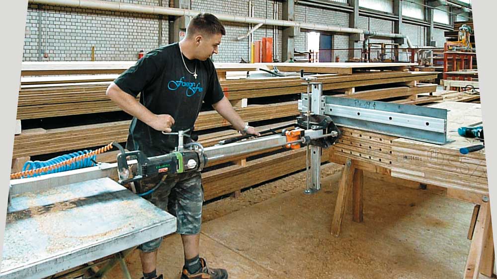
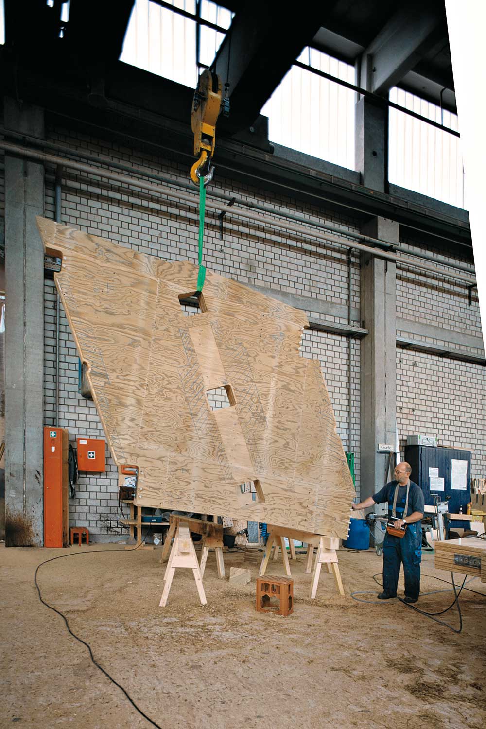
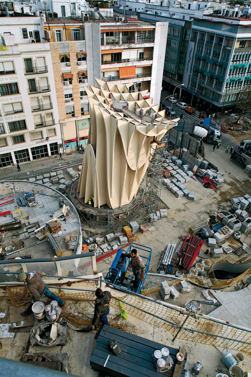
The Metropol Parasol is described to be huge trees starting from the base of six pylons that extend upwards to merge and join to appear like “parasols” serving as a shady roof in the historic centre of Seville. User spaces are stacked vertically above each other, with an archaeological museum at the basement, a market hall at ground level, and a roof filled with restaurants and bars.
The basement spans 40-metre wide and is contained in a two-storey-high steel Vierendeel frame.
The market hall, that sits above the basement, has a steel and concrete composite roof that extends five metres above ground.
The restaurants and bars sits in a lattice grid of polyurethane-coated laminated-timber sheets at 21.5 metres above ground.
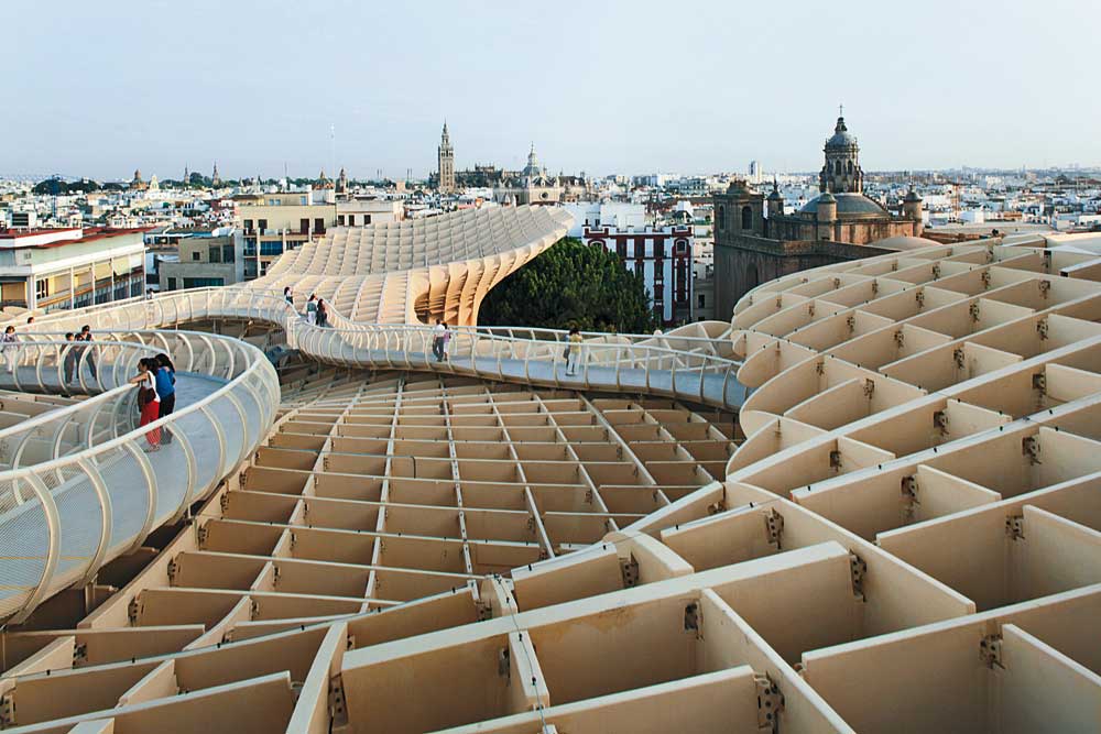
A panoramic route winds through the free form roof and two cylindrical load-bearing concrete towers wrapped in timber sheeting contain lift shafts and support a linking platform where the restaurant facilities are located. The platform is in a reinforced concrete composite form of construction from which the timber lattice grid is suspended. The shafts of the other four parasols and the 11,000 m² undulating roof structure consist almost entirely of laminated-timber elements.

To explain the appearance of the square lattice design by the German architect, Jürgen Mayer H, quoted from Rowan Moore’s review on The Guardian:
The idea of the Parasol was to make shade, a valuable commodity in a city as hot as Seville, and so make the square more habitable.
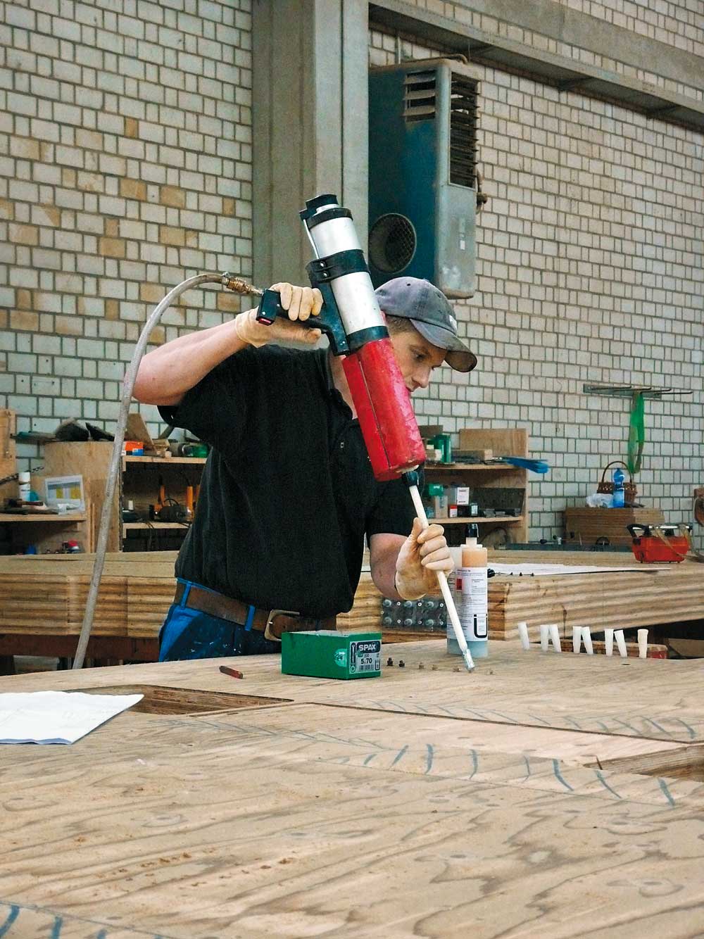
Continuing our research on the Parasol, we found out that BESISTA® tension rod systems with a durable hot-dip galvanized finish was used to assemble and create the stable structure.
3,600 BESISTA® tension rod systems, with all their high-quality features, blend seamlessly with the structure’s organic forms. Devised by Anton-Peter Betschart, the BESISTA® tension rod system with its consistently supreme standards of safety and reliability vouches for the stability of the filigree assembly. After scooping the red dot design award in 2012, the exceptional design con-cept was nominated for the 2013 Mies van der Rohe Award.

From the reading, it is apparent that the Seville roof was constructed out of reinforced concrete composite and laminated timber and steel held together by high-performance glue that is tested to be able to withstand the heat of Seville and BESISTA® tension rod systems. We would like to consider similar building materials for our installation and would research more into similar means of construction that would be most suitable for the construction of our installation.
Week 8
Simple, Fluid, Curvilinear
During this interim, we further developed the open ribbon form which we have decided on and researched further into possible construction methods.
Development of Form
In order to visualise the form in the natural environment, we thought about the scale of the form by multiplying it in the ratio of 1:50 (1=10cm).
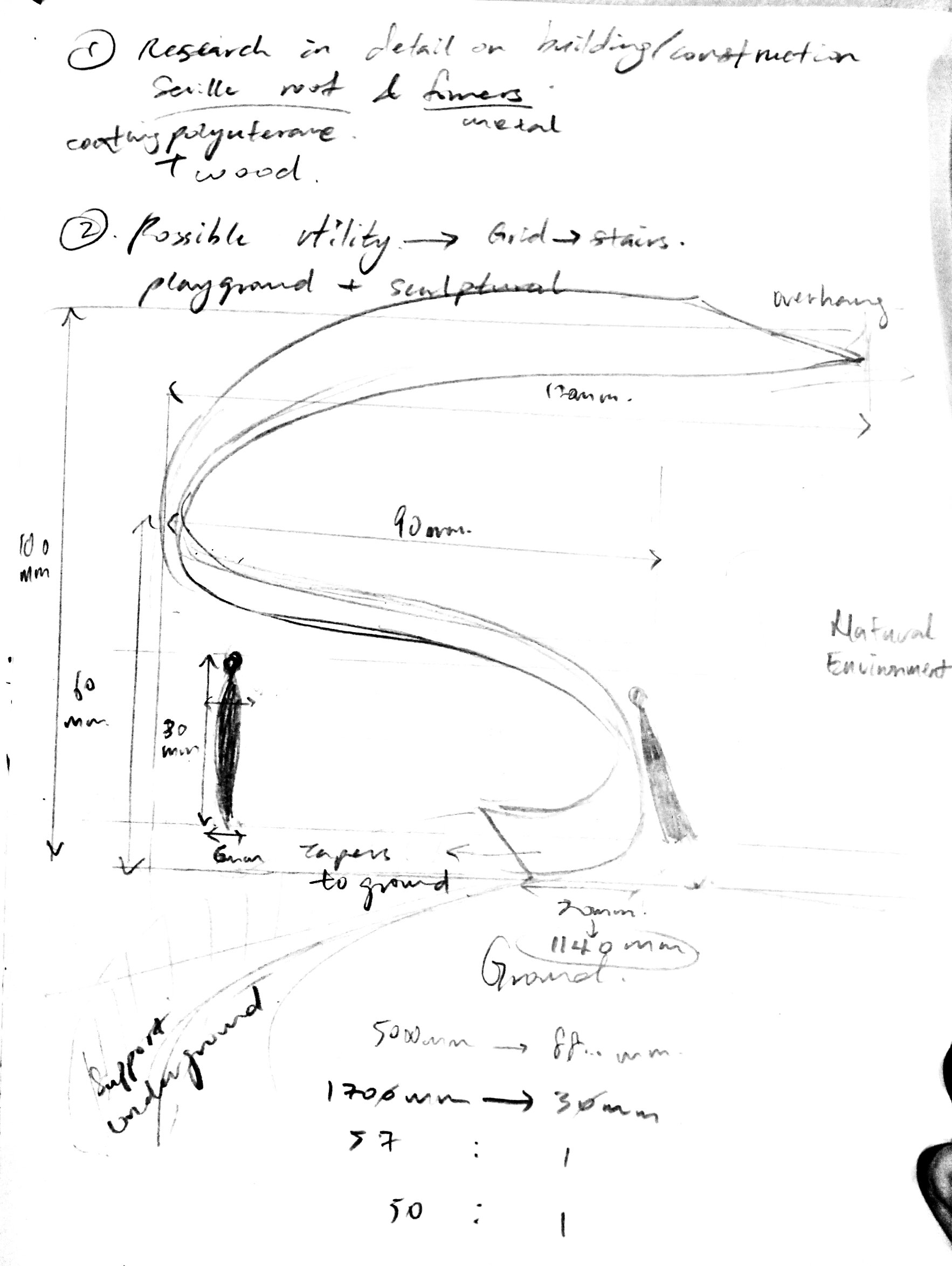
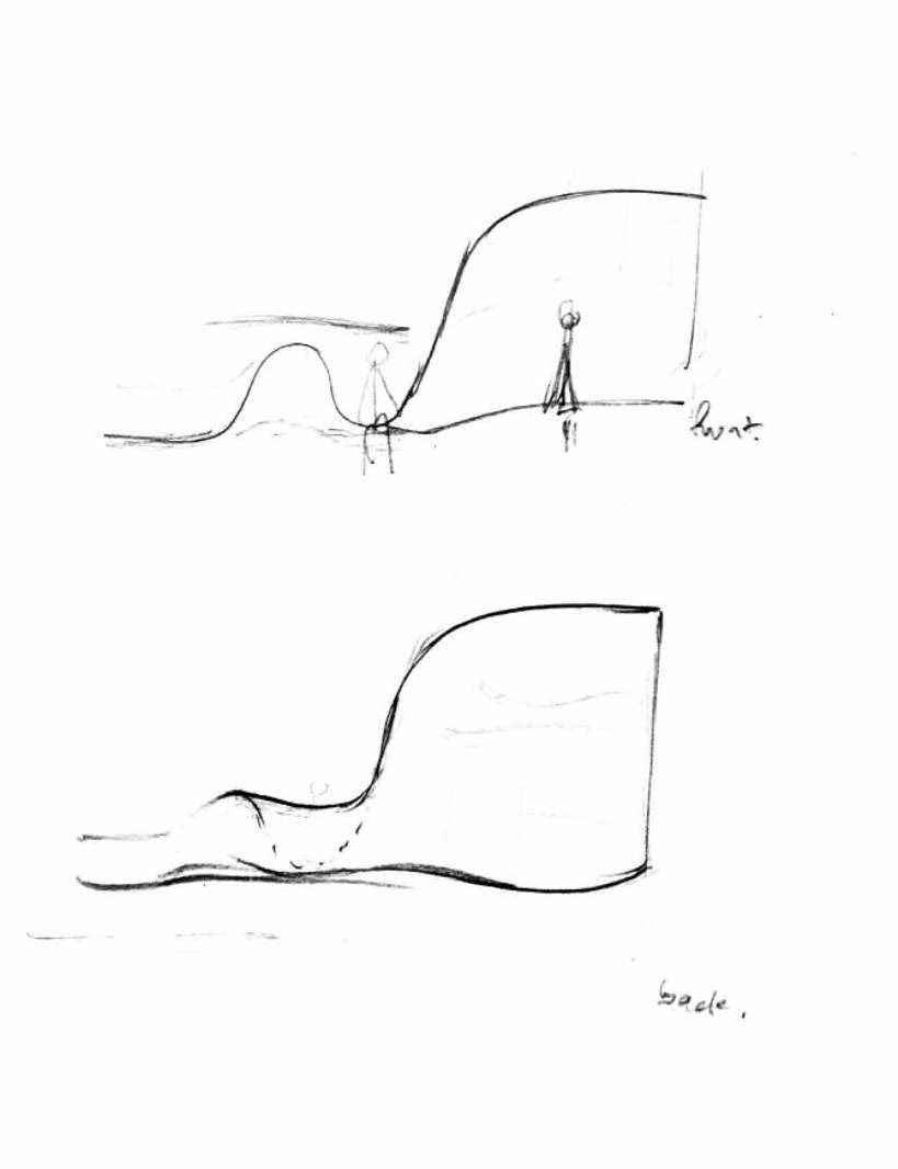
Alongside deciding on the real scale of the installation, we came up with a few different iterations of the form, exploring mainly on alterations to the base of the installation (where most people would interact with at their height). For example, a form that curves and taper to the ground would provide more void for people to stand in, whereas a form that curves and meets the ground inclined at an angle would provide a slope or protruded surface for people to lean or sit on.

Additionally, we realised that the curvilinear surface for the middle section of the installation can serve as a second deck where people can access by climbing on the grids of the structure.
To design a more stable standing sculptural installation, we thought of incorporating some supporting beams that is attached to the sculpture underground. The underground supporting beams would act like an anchor or the root of the sculpture, holding the sculpture in a stable upright position.

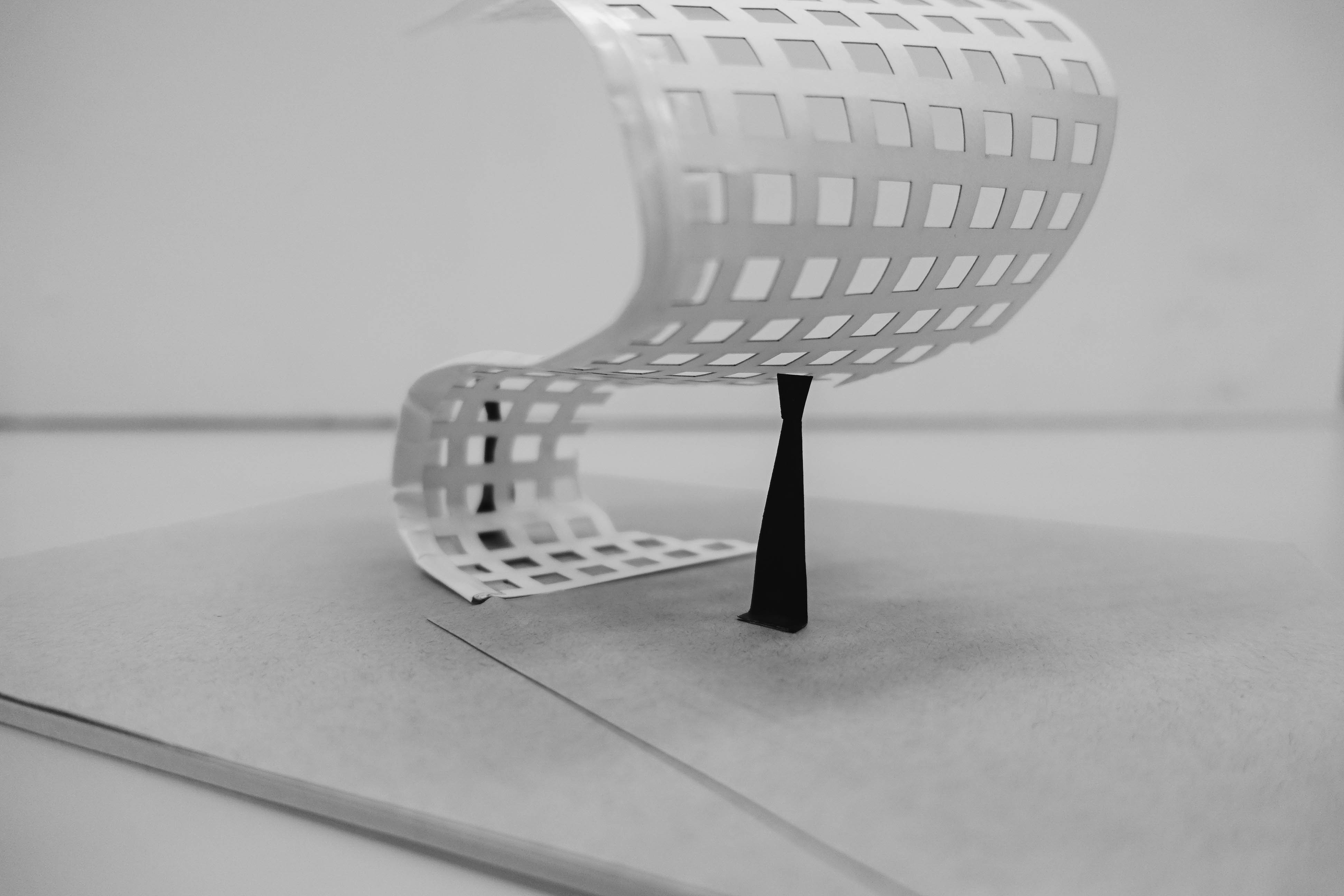
Instead of constantly repeating a fix number of grids in a systematic order to create the curvilinear surface of the installation, we would like to bring attention back to our idea of personal and shared spaces in the single installation by playing with transparency of material and varying depth. As such, we have subtracted voids of the curvilinear surface as it progresses from up to down. The opacity of the curvilinear surface near the base reflects mass and describes a gravitational pull, making the sculpture appear more stable and secure at the base and more porous as it progresses upwards.
In addition, to echo the improvisational aspect of the natural environment where we intend to place our installation, we incorporated randomness to the order of the squared grids as shown in the two right-most 3d renderings in the image below.

As we brainstormed on the possible incorporation of functions to the form of the design, we came up with the idea of a open flap that serves as a seat. However we thought that the feasibility of the incorporation is very low as the flap may breakaway from the installation due to wear and tear as a result of human activities.

We liked the idea of the open flap inspired from the dog-ear pages of a paper (eg. in an old textbook) as it evokes feeling of nostalgia and hints on the revelation of what is beneath the surface. As a further development on the open flap, we came up with a curved extrusion that is joined permanently to the curvilinear surface of the installation to serve as both seating and shelving.

We decided on the direction of the curve extrusion by connecting them with an imaginary chain in void to suggest fluidity and continuity.
Materials and construction methods
Some materials we would like to consider with construction would be:
- Concrete UHPC
- Polyurethane
- Water jet cutter to cut a metal sheet
Future developments
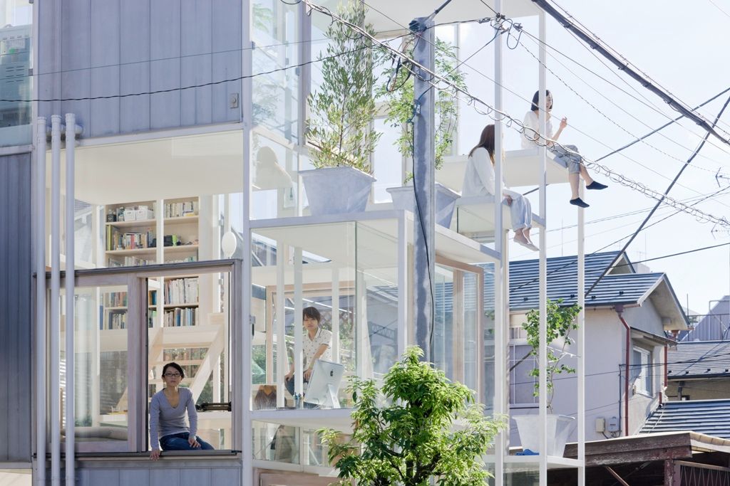
For our future developments, we have looked at two different presentation of architectural design – daring vs cautious. For example, House H by Sou Fujimoto describe clearly defined rooms within a singular continous living space that features two ladies sitting precariously on the edge of a second storey veranda, displaying a daring architectural design. In contrast to House H, we would like to create an installation that is more cautious by integrating safety considerations into our design.
We would also like to consider using Glass Fibre Reinforced Concrete GFRC which we would share more about in our next post. You may read up more on its sustainable quality here.
Week 7
Recollecting our Idea
Inspiration
Our installation is inspired from the meaning of Nan yang; derived from the Southern Sea. We want to develop awareness on the school’s heritage by making reference to the origin of the school’s name, represented by a form that is both fluid and dynamic; combining private and public spaces in a seamless transition in a single installation to encourage people in NTU to interact with the installation in both personal and shared ways.
Returning to concept 1 (lighter form) in week 5, we continued to explore the mass and void in a fluid structure to be placed in a natural space within NTU.
Reflection
From feedbacks received in week 6, we would like to move away from the form of a moebius loop and return to the ribbon form that open and moves. Also, we have decided to subtract any straight folds and corners so as to avoid interrupting the fluid motion of the sculptural installation. We would also like to adopt using different materials/ different construction techniques to reinforce the utilitarian aspects of the installation without compromising on the emotional aesthetics that the sculptural form exude.
Further Developments
Formative references
To give ourselves a better understanding of how to construct the fluid form and integrate different materials into its construction, we draw inspiration from a few existing architecture, installation and furniture works.


Incorporation (translating the meaning of fluidity into sculptural forms)
Making reference to the Seville roof, we developed the ribbon form that begins as an open roof, intended to be constructed in a similar way to the Seville roof, that curves into a closer space (material becomes denser with closed grids to eventually taper and join with the ground).

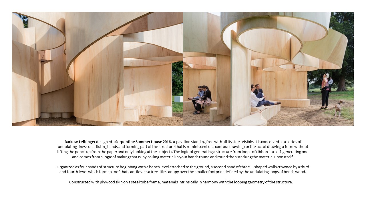
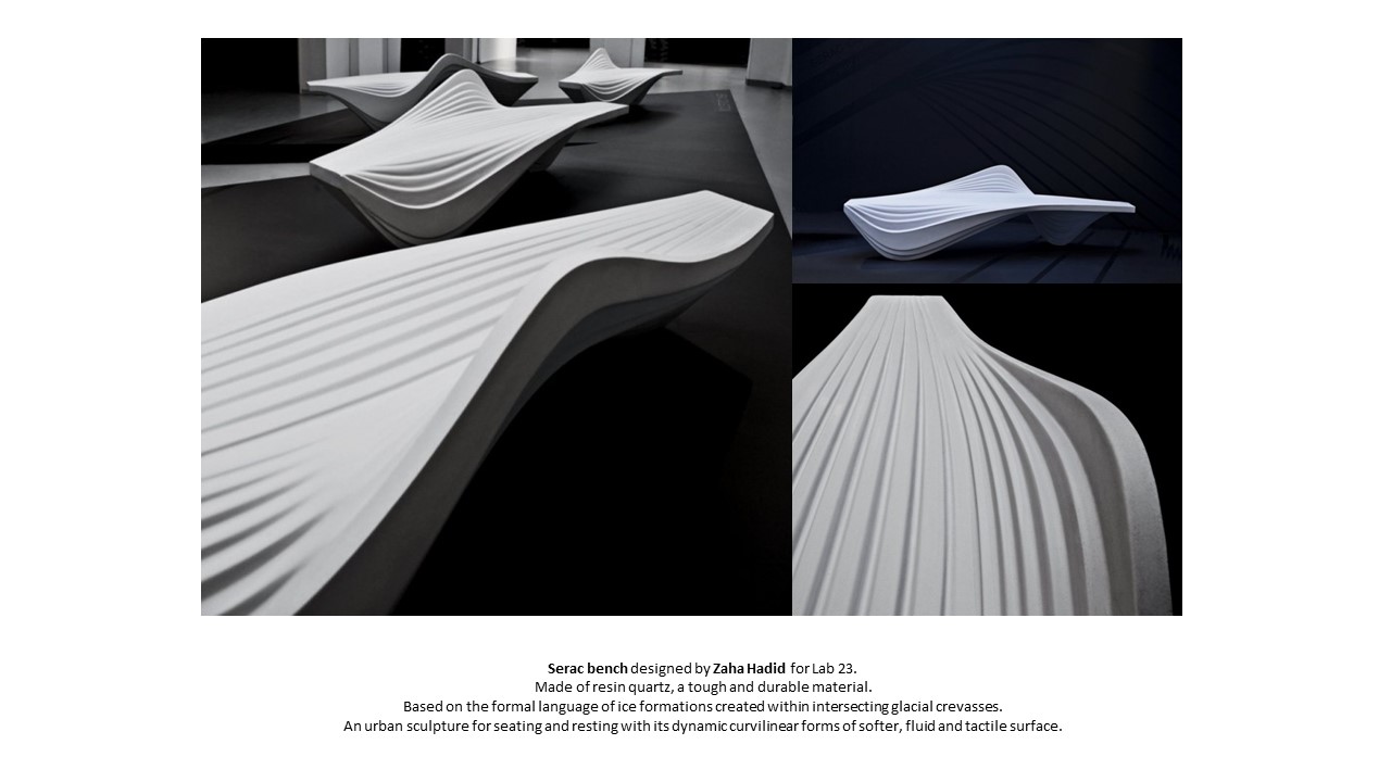
As a development to the ribbon form, we research on fluid forms by looking at Toyo Ito’s Taichung Metropolitan Opera House, Barkow Leibinger’s Serpentine Summer House 2016 and Zaha Hadid’s Serac Bench. We extended and folded one edge of the curvilinear plane to create a more organic form that incorporates utilitarian considerations for the sculpture to serve both functions as a private and public space.


For the construction of the foam model, we thought of making reference to Marc Fornes/Theverymany‘s installation “Minima | Maxima” with the use of aluminium modules or joining wooden plates together in a similar fashion to create the curved surfaces.

To emphasize on the personal space within the sculpture, we choose to seamlessly integrate the gridded structure from earlier development into the later development to serve as an open shelter without interrupting the fluidity of the form.
By representing the roof with the uniform gridded form, we want to reinforce the personal space within the installation and encourage our audience in the space to engage in visual meditation with the gridded shadow and its illuminated square voids casted upon him by the natural light. We hope that the user can focus on his consciousness as he meditates in the circular void sheltered by the square grids to achieve inner peace.
In a more symbolic explanation, the square provides well established boundary lines whilst the circle defines area. While the boundary lines of the square gives the user the feeling of security, its sharp edges and corners is observed by people outside the space as a delimitation, a sign that tells them not to go beyond the lines.
Future explorations
We would like to research in detail to find out which materials and construction methods work best to bring out the fluidity of the form.
Week 6

Week 6
We decided to work on Concept 1 (lighter form) to further explore on mass and void in a fluid structure to be placed in a public space in NTU.
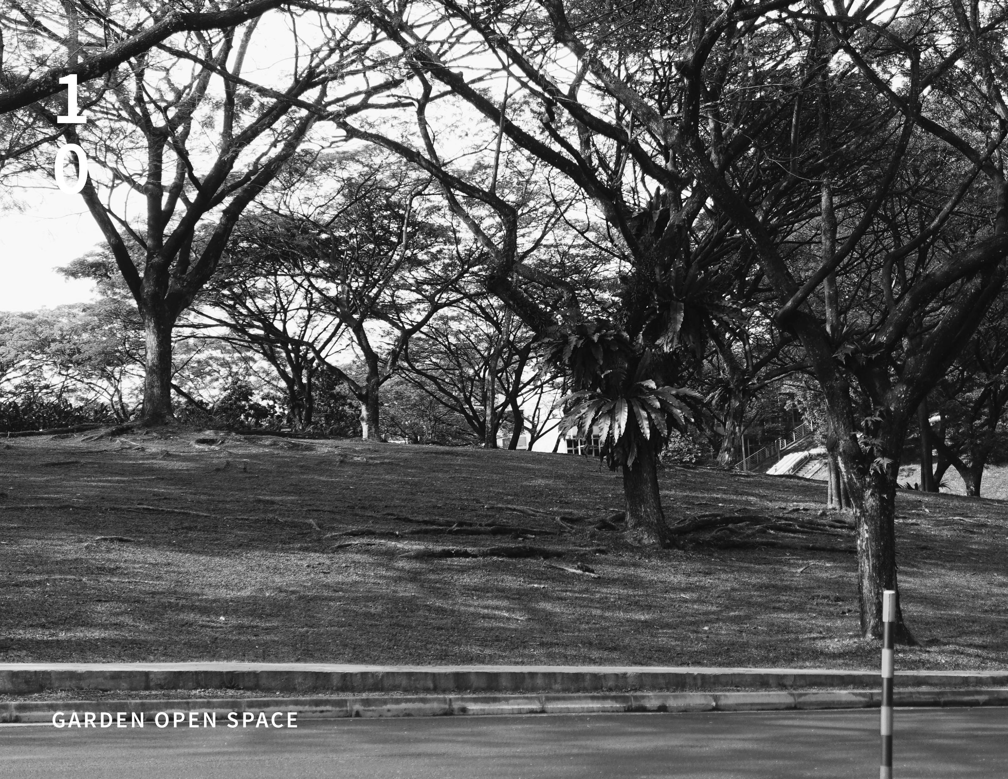
To be more specific with our selection of space in NTU, we thought of incorporating our installation within a natural space to achieve a balance between architectural installation and nature.
Also, we want to utilise the natural shading of the existing natural space in NTU for a cooler experience.
Defining Public and Private Space
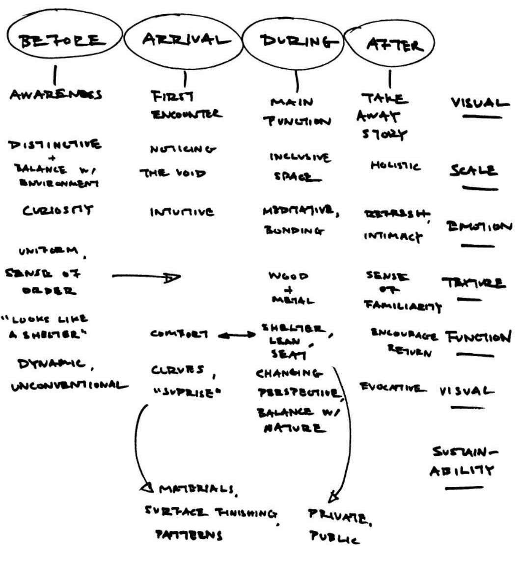
We drafted a mind map to develop the user journey which helps us define their experience in each stage of the journey.
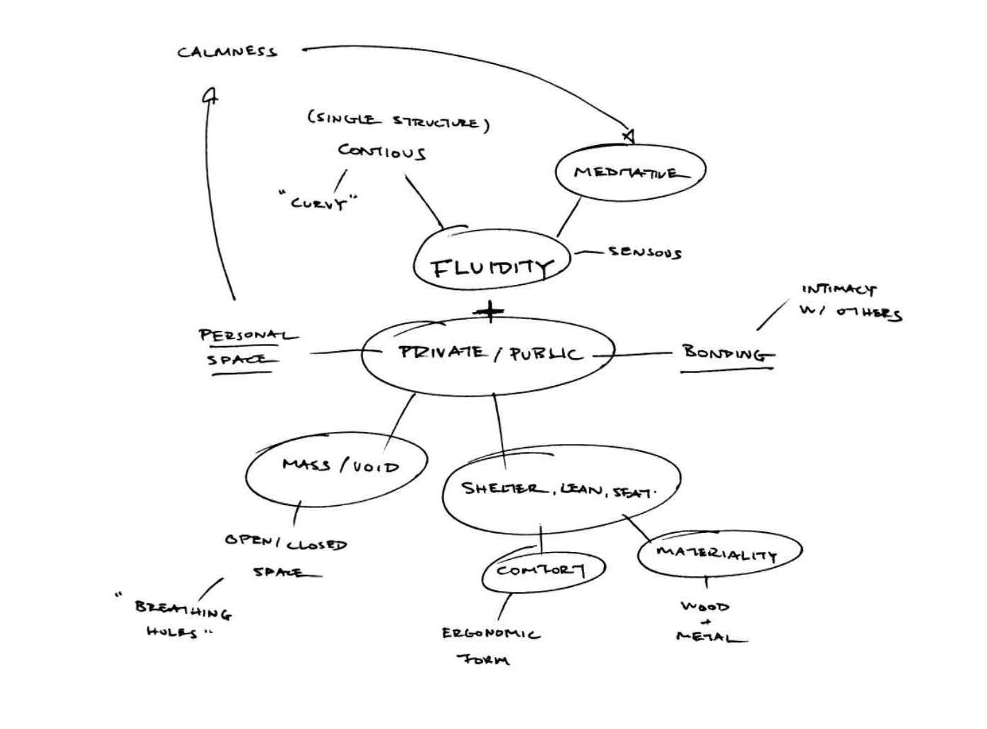
Identifying the key words for the aesthetics and function of our concept.
Further exploration with Concept 1
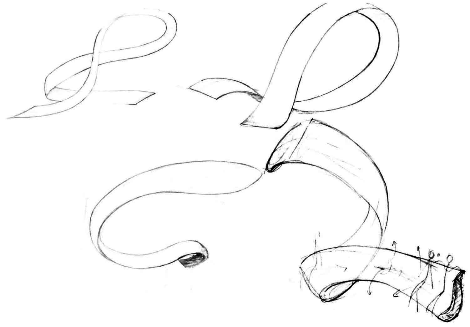
Interaction with the Installation
We made a mock up of a continuous curvilinear structure that encompasses both public and private space in a seamless transition.

People in NTU (students, faculty members and visitors) can interact with the structure as shown in the image above.
Considerations of Materiality
To further develop our idea, we retain the material considerations from Concept 2, which were wooden grid structure, to build the curvilinear form of Concept 1 because we thought that a gridded structure presents a more open structure that gives the sculpture permeability, allowing the sculpture to ‘breathe’ and the user to connect with the outside while being on the inside.
In addition, the gridded structure can serve to convey a visual direction in our installation as the lines give a sense of order in the construction of the fluid form.
With reference to the Seville shelter, we would like to make use of a similar gridded structure for the construction of our installation.
The gridded structure can serve aesthetically as a porous membrane that balances void and mass. To add on, we imagined that the organised and controlled shadows casted by the gridded architecture of the installation under natural light can stimulate visual meditation, using the sense of sight to focus on one’s consciousness.
Perhaps glass planes can be held into place within the grids that serves as a rain shelter. Our choice of glass would be for its transparency into the natural environment, which allows people to look up at the sky and relax their eyes with the greenery surrounding the installation.
Juxtaposing a gridded structure with the natural environment was meant to achieve a sense of balance between man and nature whilst preserving man’s desire for order within chaos.
We intend to explore different smaller modules to be used in the construction of the overall dynamic form.
As part of our exploration on the construction of the wooden grid structure, we made some half lap joints with pine wood.
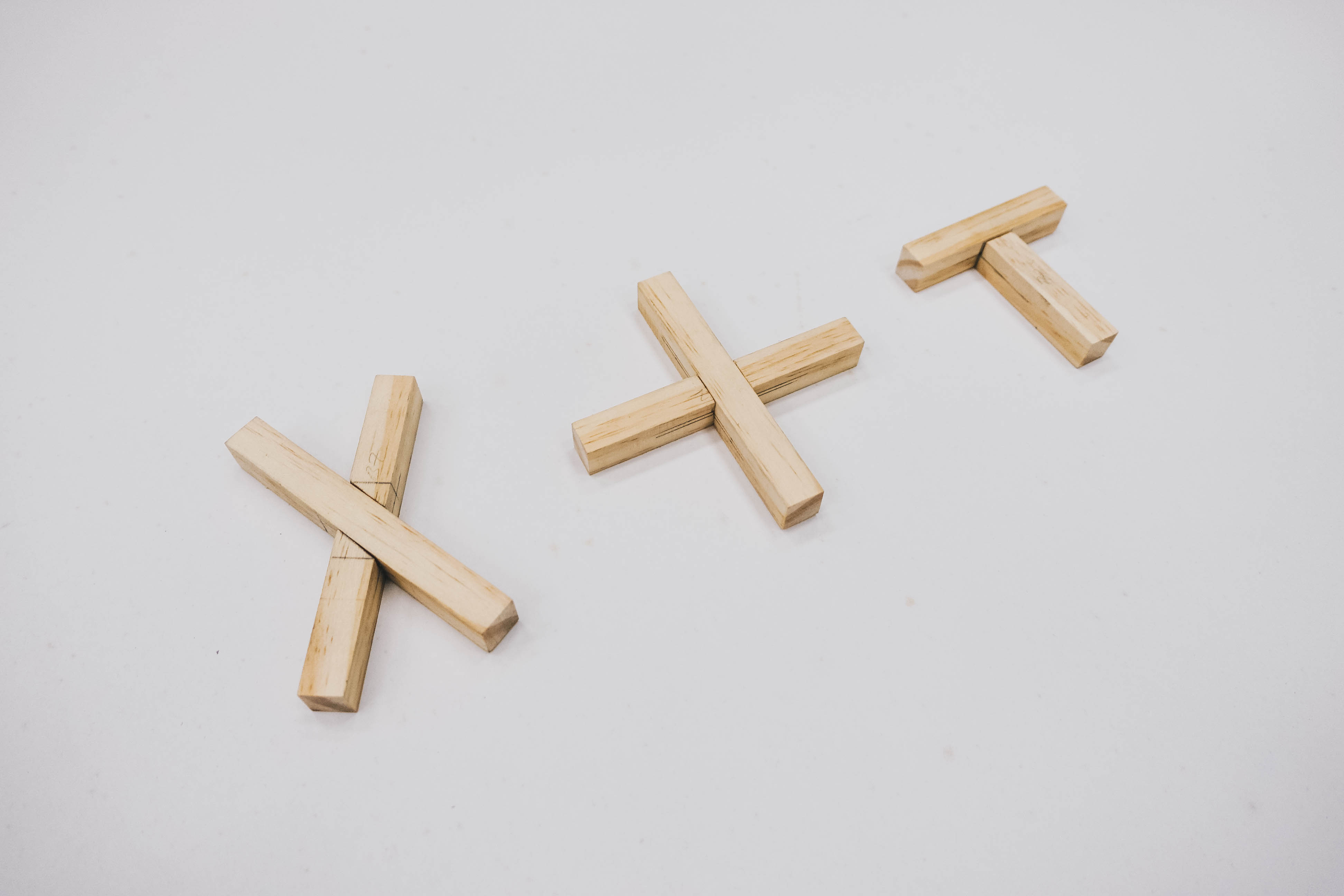
Perhaps the cross lap joints can be chamfered at different angle as they connect to form a dynamic curvilinear plane.