The process
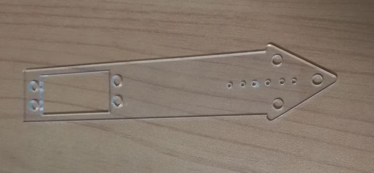
The above is our initial acrylic arm that join the main motor and the finger motor. When making this, we realise that the hole were too small and we decided to drill it into a M2 hole. This arm was also too short and we did a 3D printed version later to blend with the black coloured motors.
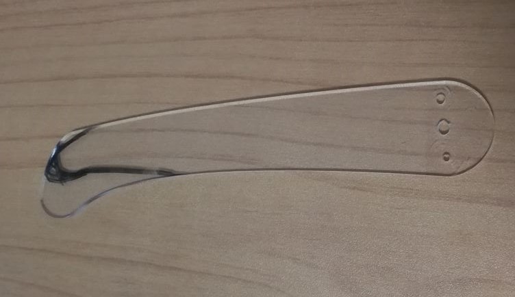
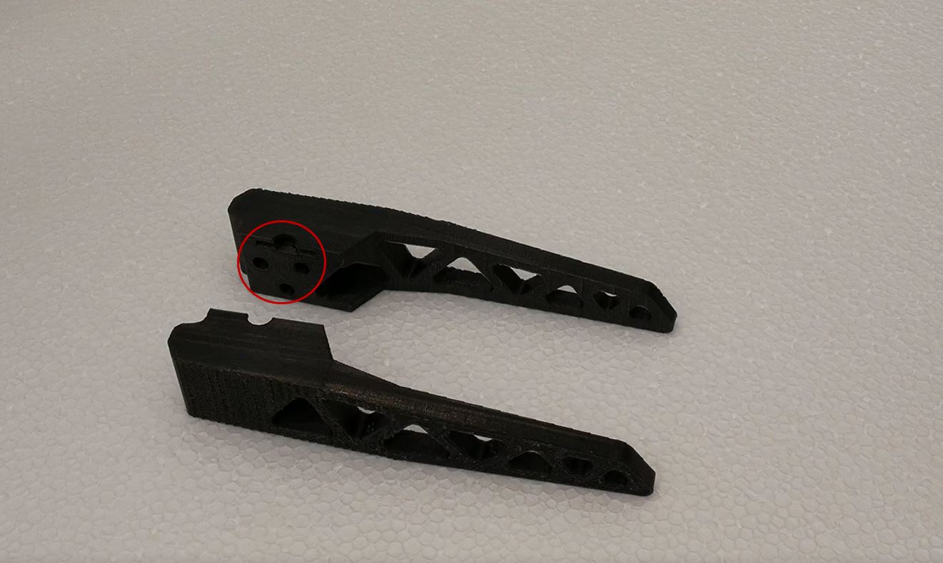
The above is the finger piece was too short and we changed our design to type from the top instead of typing in a tapping motion. The marker-ed part was indicated to change to design as it was too hard for this design to type from the top. We added abit of the length to let the finger type without moving up too much.
The above is the base of the type bot. The design allows the base to be put together without any glue with the 3 circles positioned in a triangle manner and it will be slotted into the inlets on the other side. There is a slot that allows us to slot in the white part of the motor as shown below so that the motor will be stable and would not move around.
The triangle cut-outs of the base are designed to attach any other compartments if we want to add any stabilizers or grip in the future.
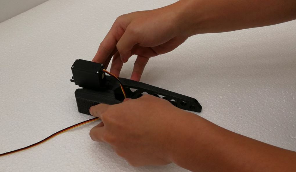
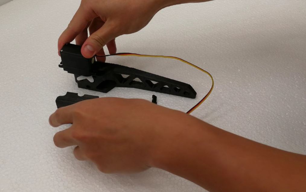
The images below is a 3D printed casing that will be holding onto the base motor and the main motor that holds the main arm of the typebot. The casing is design so that motors are slotted into the casing, and then tighten with folded paper.


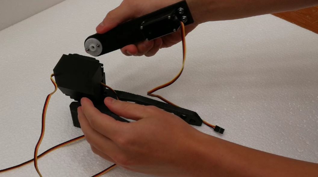
The above is the addition of the main arm that will hold on to the finger and the finger motor. We use M4 12mm screws and nuts to secure the motor so that we don’t use glue.
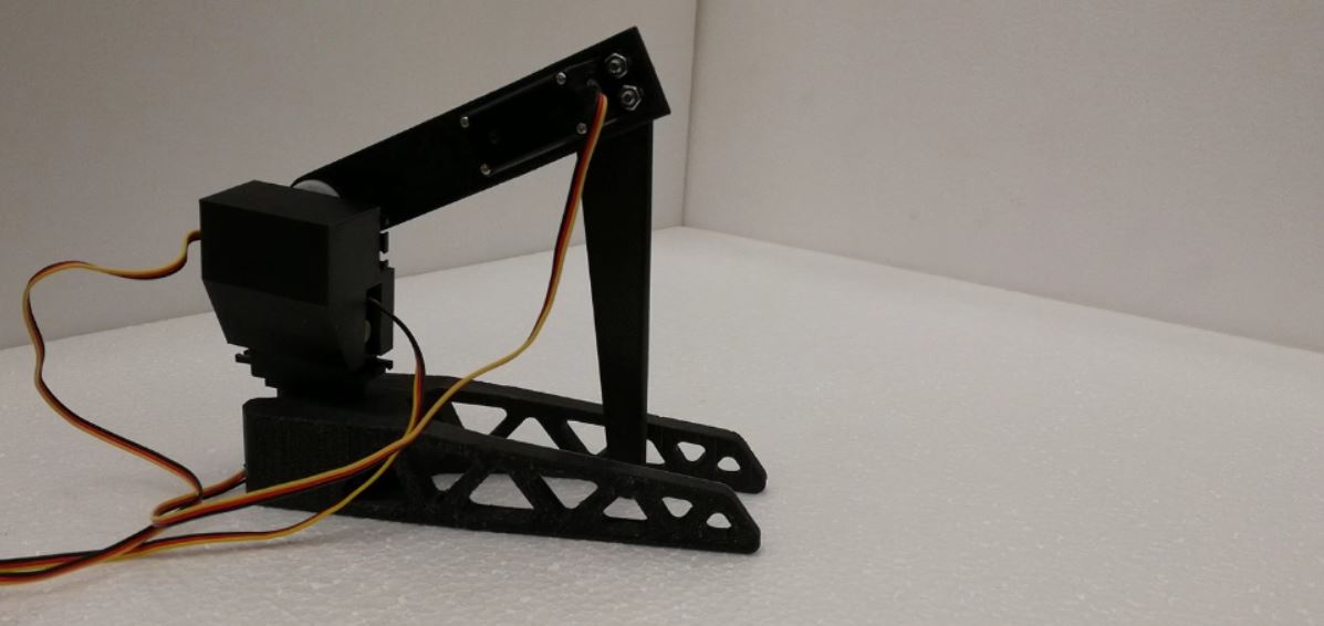
Its almost done! The finger is attached by using M2 screws and nuts.
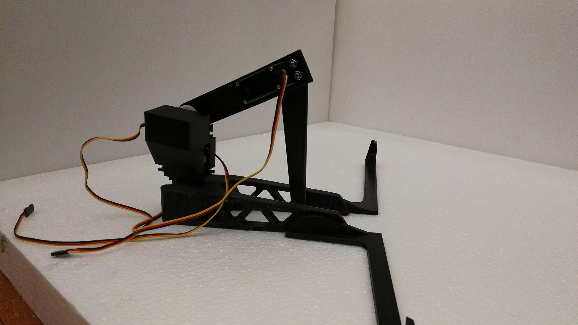
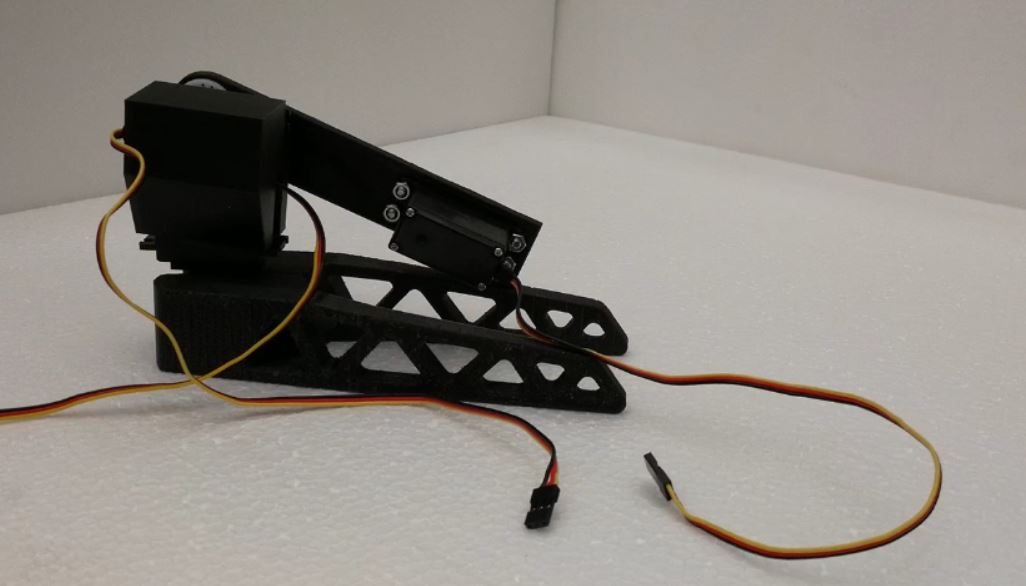
Finally its done! We added 2 ‘hands’ at the end of the base to let the type bot grab the keyboard when it is typing so that the keyboard will not move around when nudged by the finger. The keyboard can be directly placed on top of the typebot.
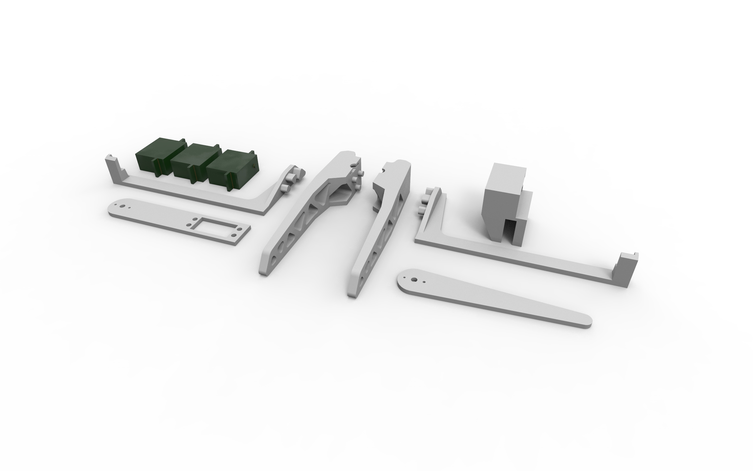
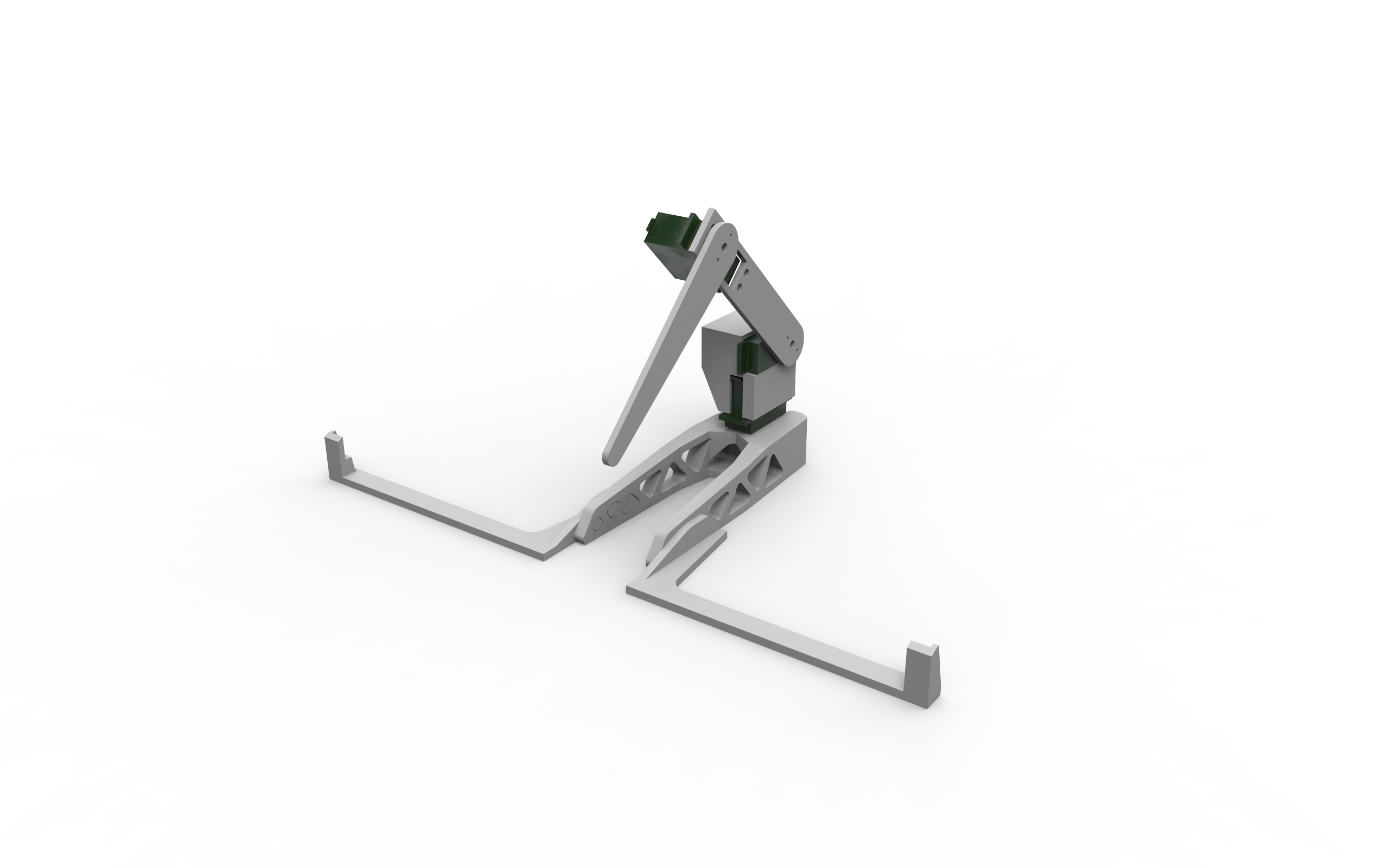 The grey parts are the 3D printed ones and the dark green parts are the placement of the motors. The below are all the parts of the typebot. Total of 7 printed parts.
Coding
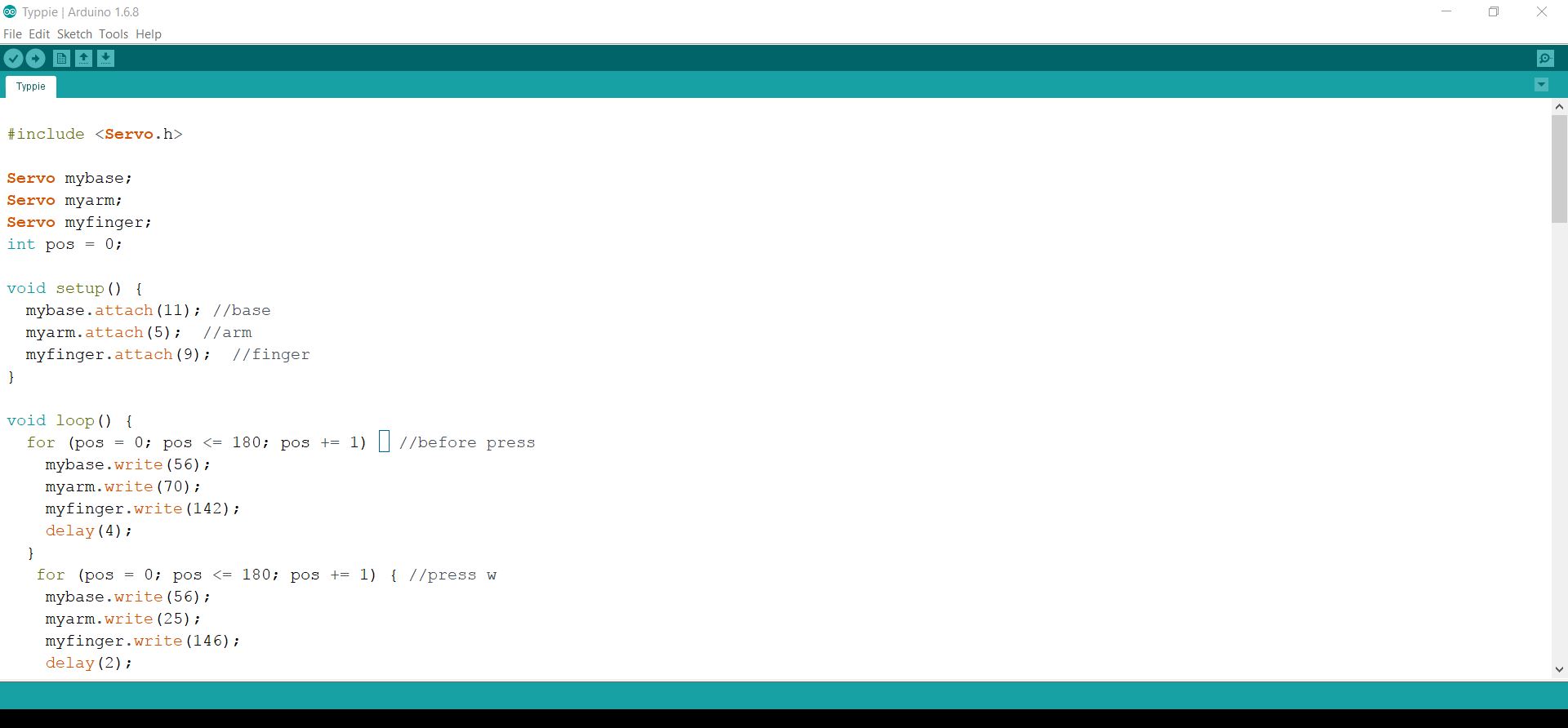
The above is the main code we used and then we duplicate it. The main problem was finding the right way to move the motor as it was always moving too fast and hit the key but did not press or hit the key so hard that the keyboard fell off the holder that we made to hold it.
At first, the angles were extremely hard to map. I think it is also due to our build. If the arm is shorter and the finger is longer, we don’t really have to calibrate every time we move from one letter to there other. The base is having some ‘recoil’ when the finger presses against the keyboard. I feel that we could add an extra piece of support below the motor so that it would not wobble backwards or forward when assembling it together. Another problem we face was creating the correct for loop. As there are many ways to control the motor, we started with controlling the speed of the motor. We also felt that the actions robot had abit angry which we kind of like. Although it was unintentional, we was able to have a glimpse of the impact of the perception of movements.

Problems
We used the code below to control the speed of the motor using (pos = pos + 5) or which ever number we feel is the correct speed. However, it was only successful for the first letter. For the subsequent letters, we changed just positioning the motors without controlling speed as we found out later that controlling the speed requires much more information to calibrate every movement of every motor, this means that the code could be triple or even more than the normal length of code we used.
Conclusion
If there is any way to make the type bot better, it would be to making it to have smoother transitions between actions.
Overall, it was a good learning experience to make and code the type bot. I feel that the mix of building the assembly and coding allows us to have a good warm-up for the upcoming projects.