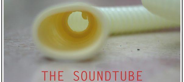
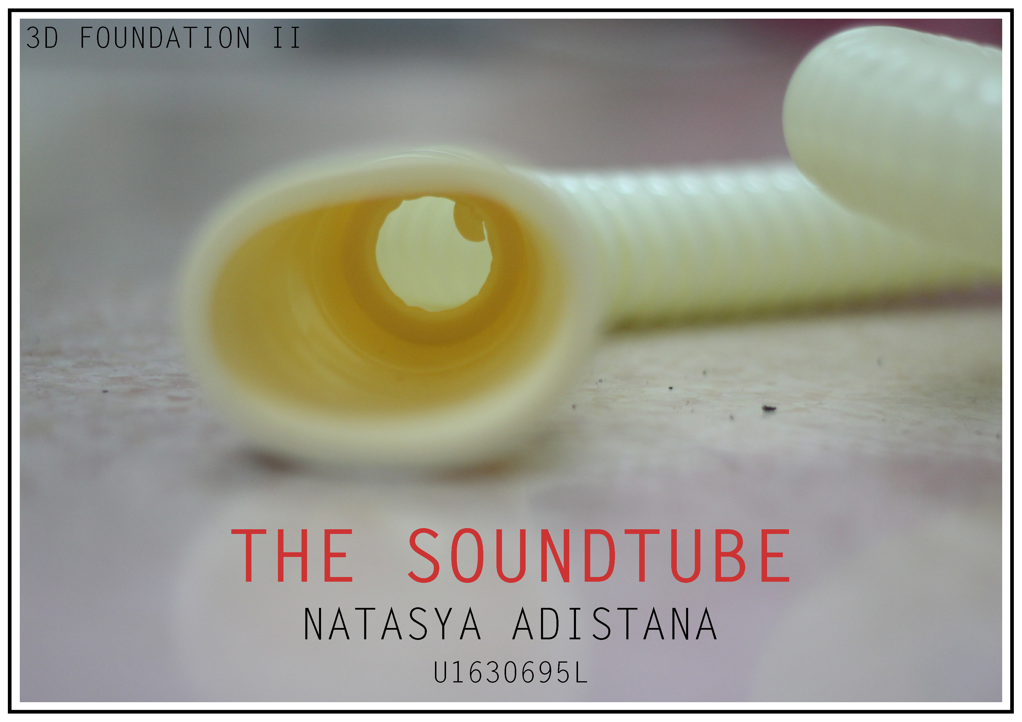
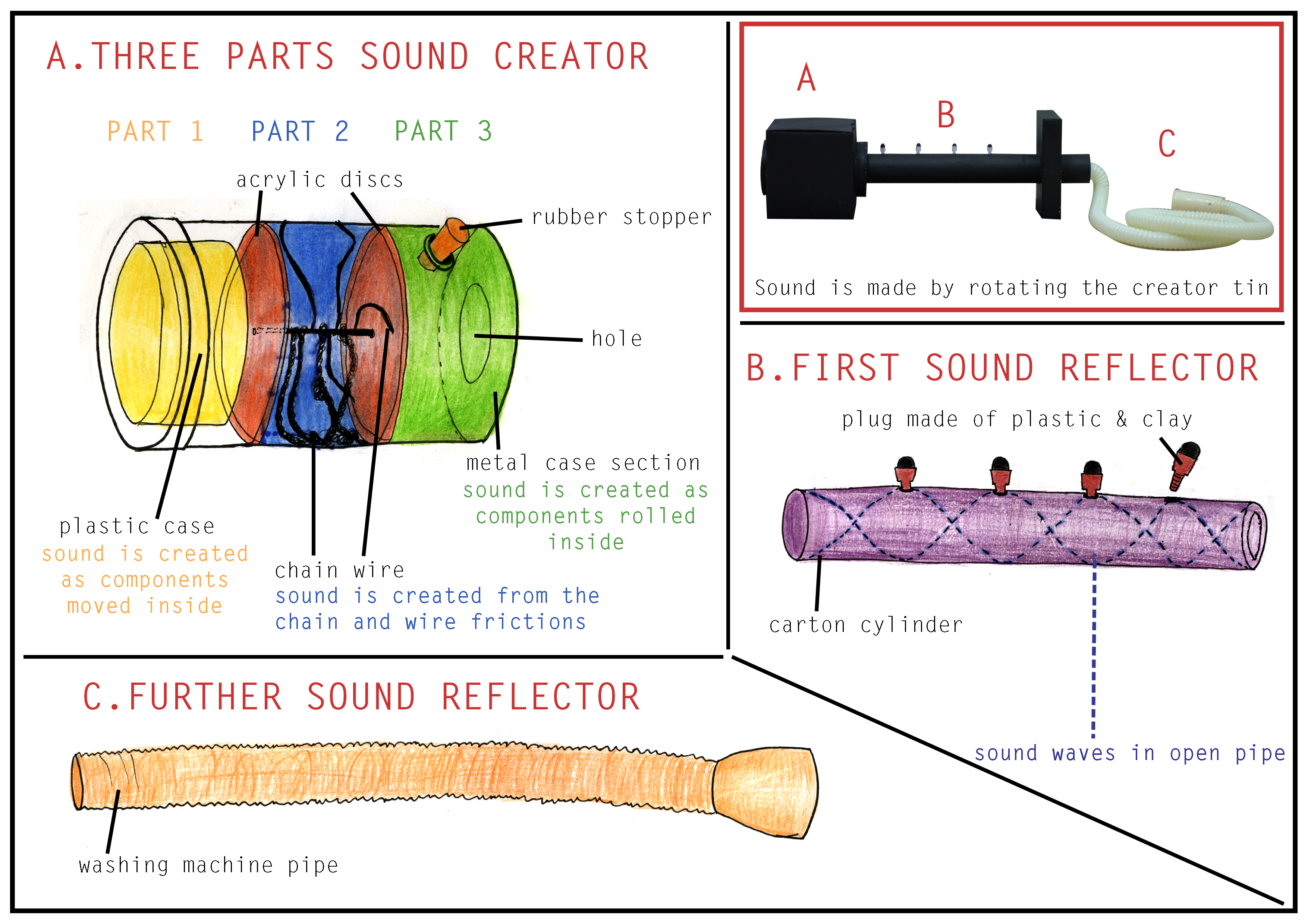
Here is the the final sound texturizer: THE SOUNDTUBE and its possible applications!
For PDF version: 002_NATASYA
I learnt to experiment a lot during this exercise! It was actually fascinating to try out different sounds 😀
I liked how it turned out to be really customizable.
An improvement I could do is to change the carton cylinder into PVC type or even metal cylinder so as to minimize the sound dampening and get a more echo-y sound. I imagined it to have an even more hollow and crisp sound. Then maybe the effect of the plug might be more obvious.
Another thing might be to change the method of creating sound by rotating to shaking the tube. Shaking might create a more intense and interesting sound instead of the plain rotation. Moreover, if I keep the idea of water inside, shaking it might allow the water sound to be heard more clearly.
Well, it was fun 😀
Will post the process and ideation real soon!
P.S. I was really scared that the texturizer will get confiscated at the airport as I bring them as hand carry, it has a lot of sharp wires and other metal elements! (I planned to do some updates at home but couldn’t find the time, sorry:( ). But good thing it didn’t get confiscated and I still have it with me now :’)
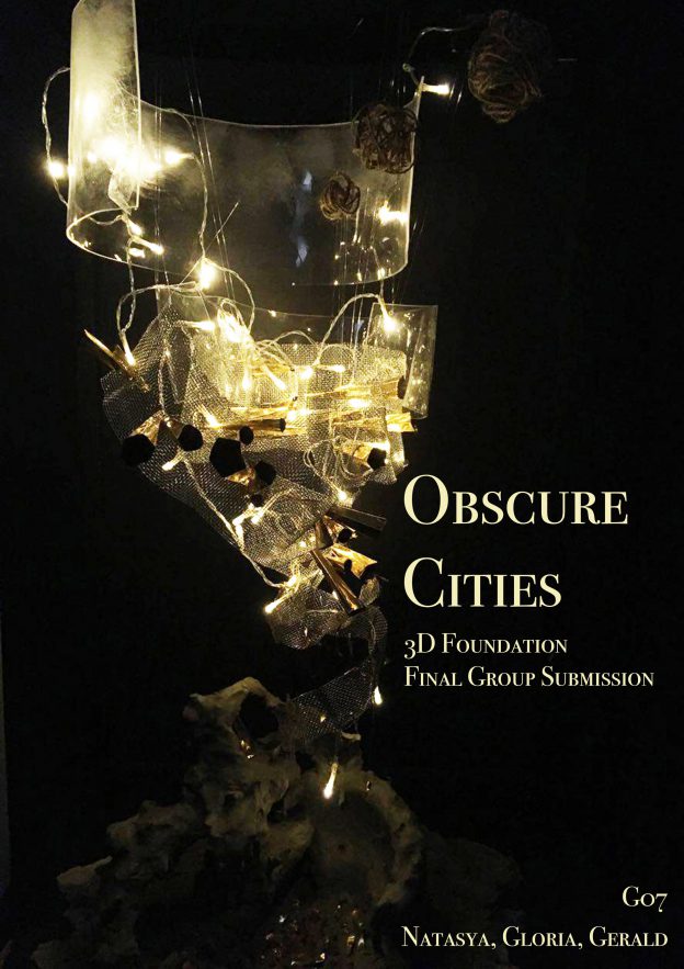
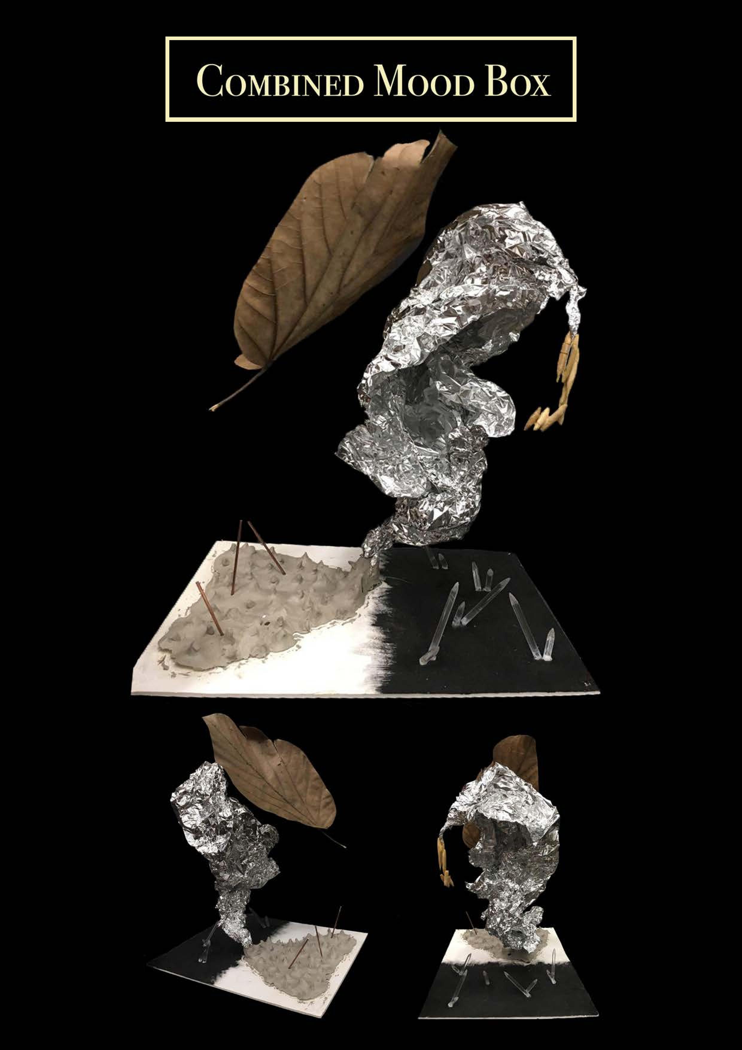
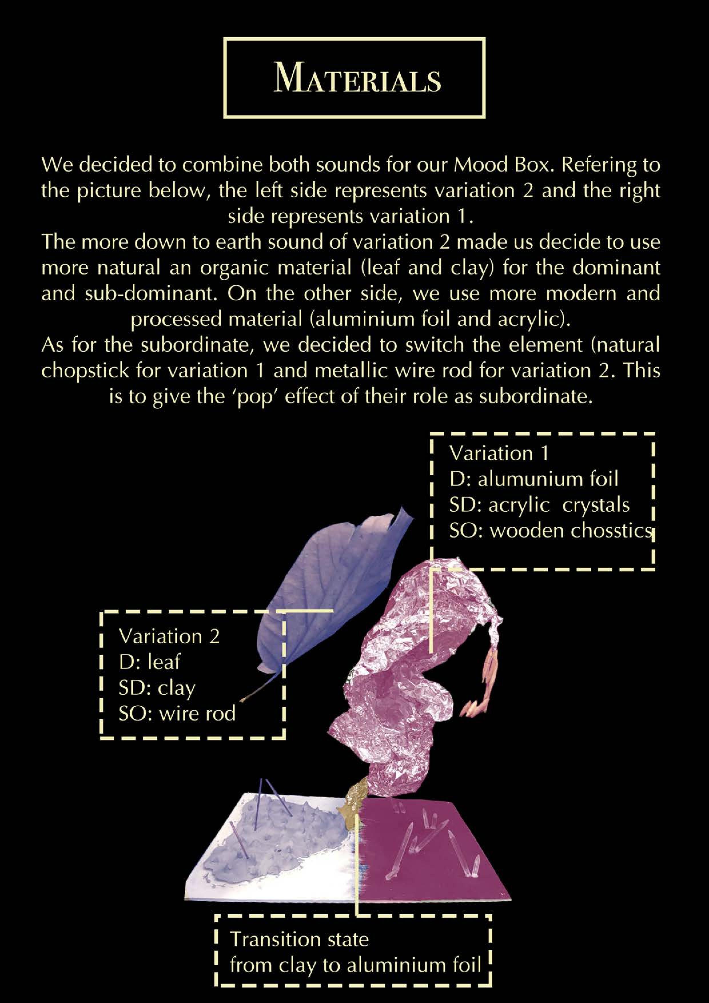
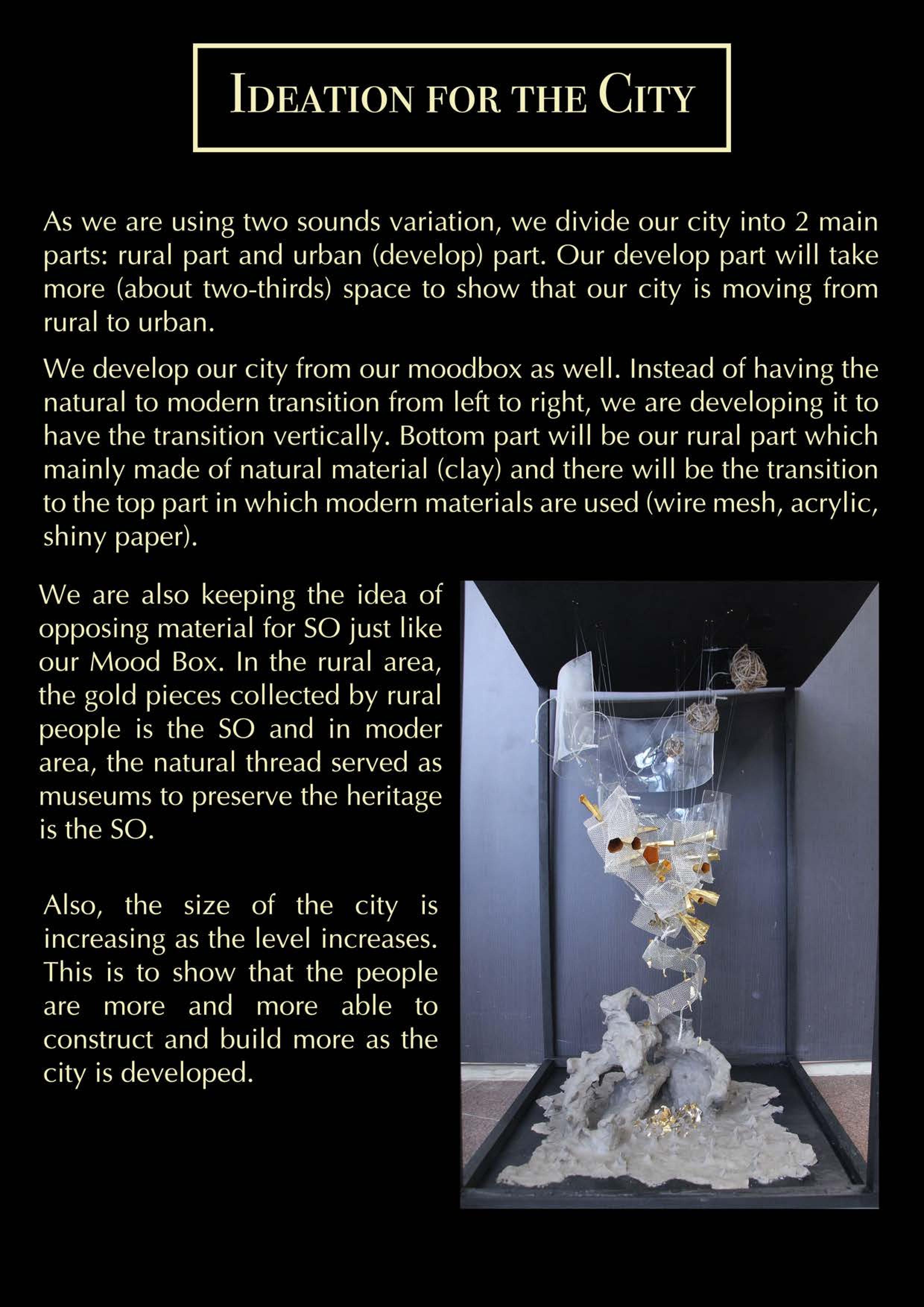
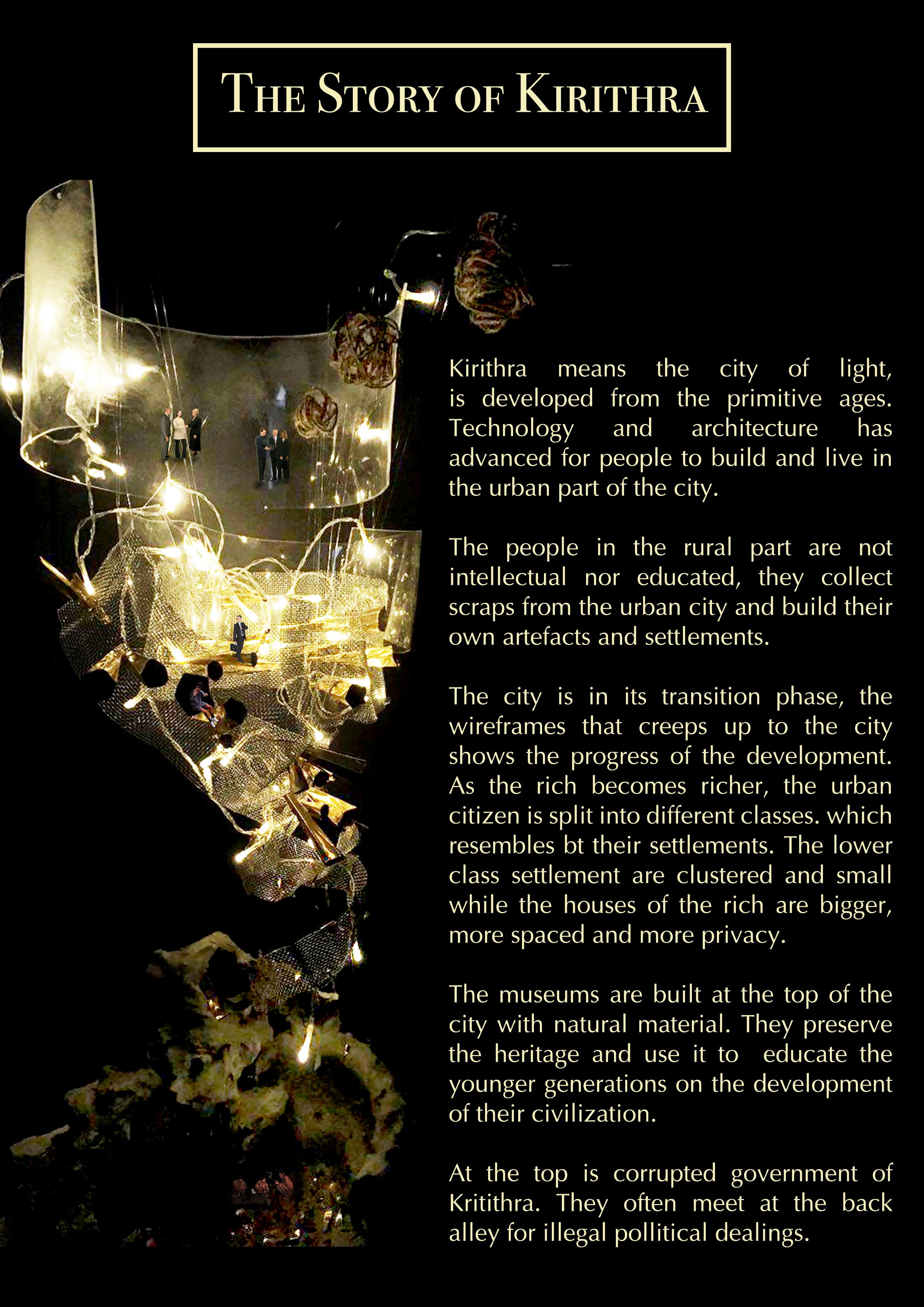
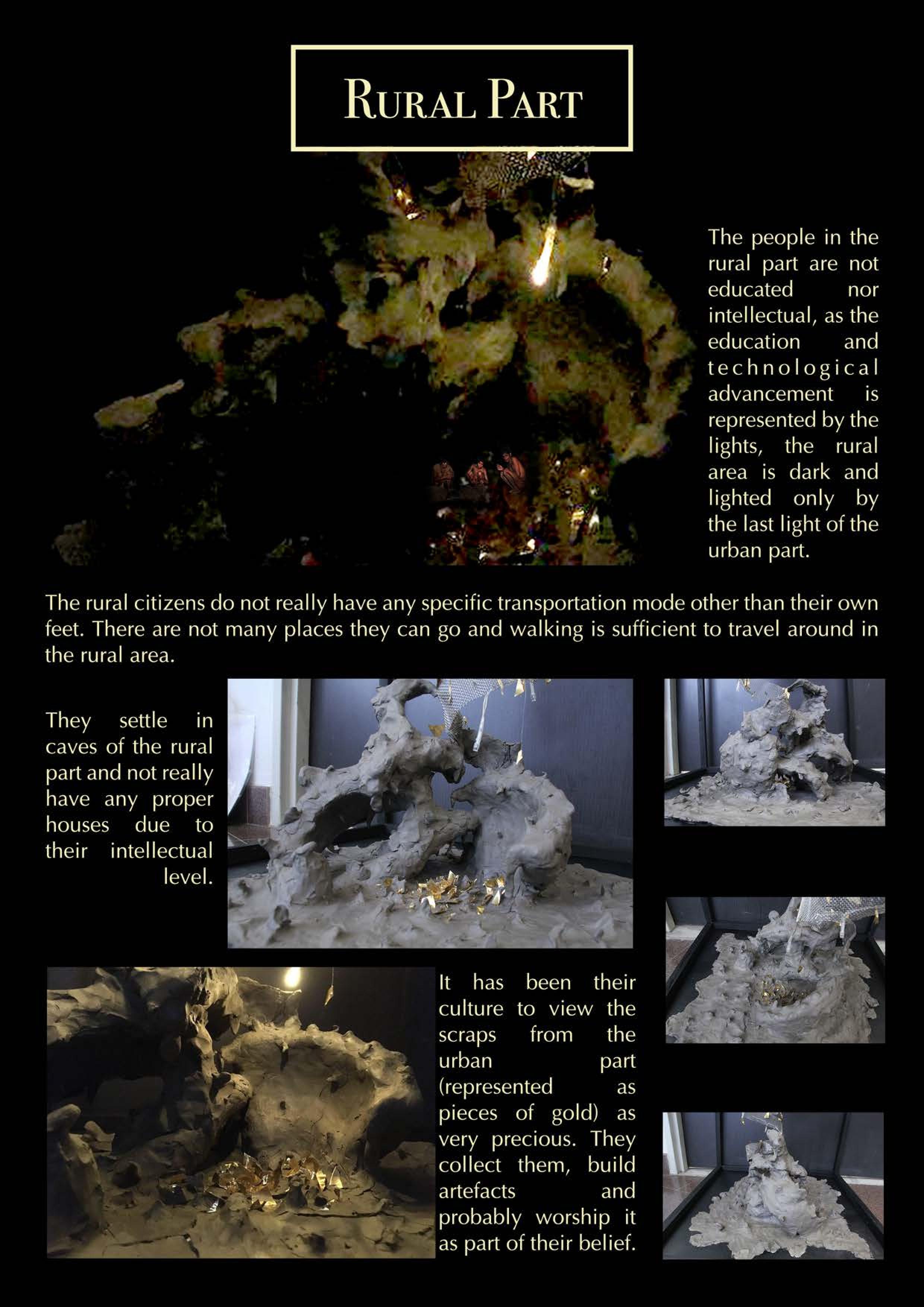
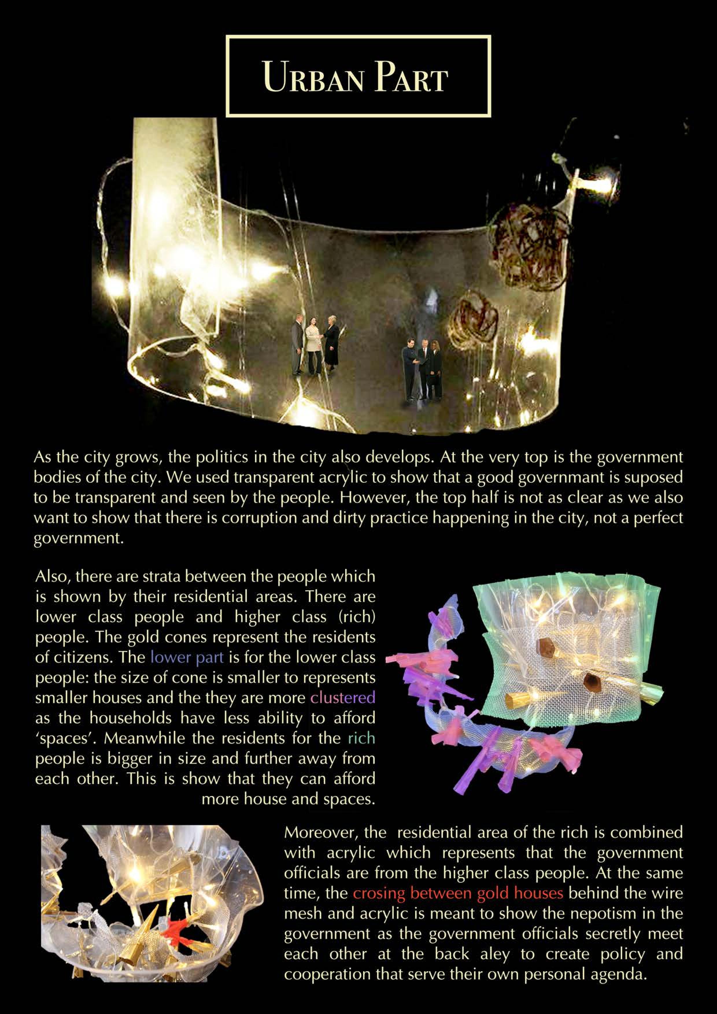
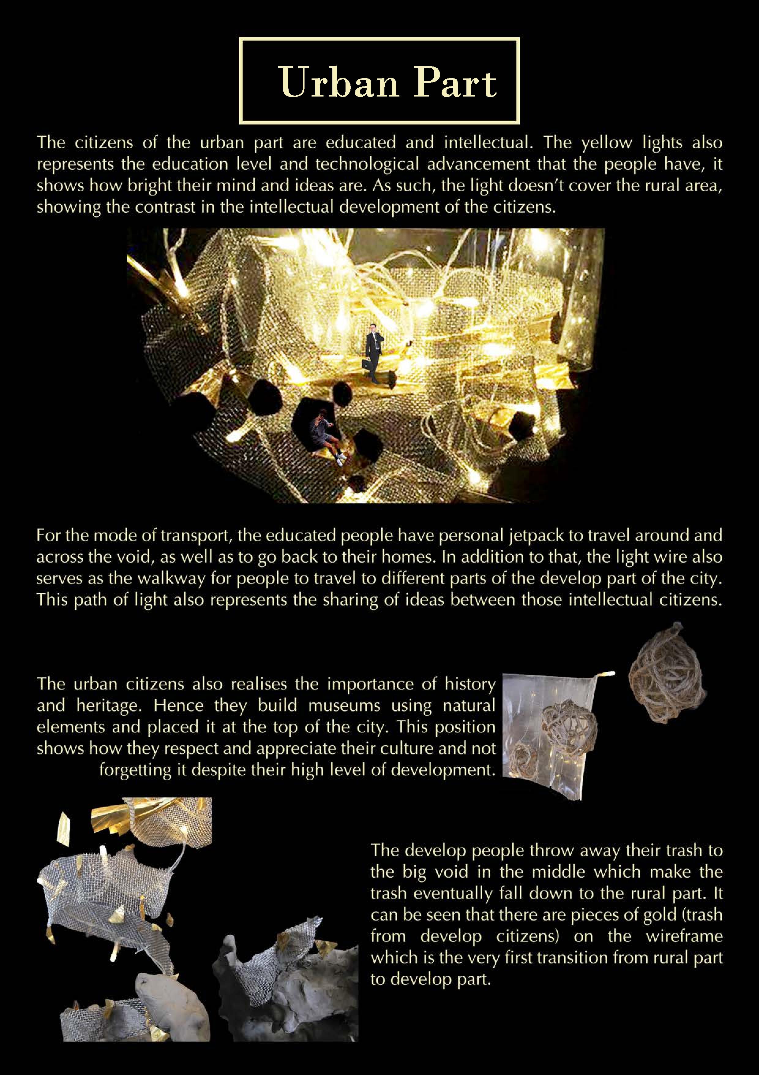
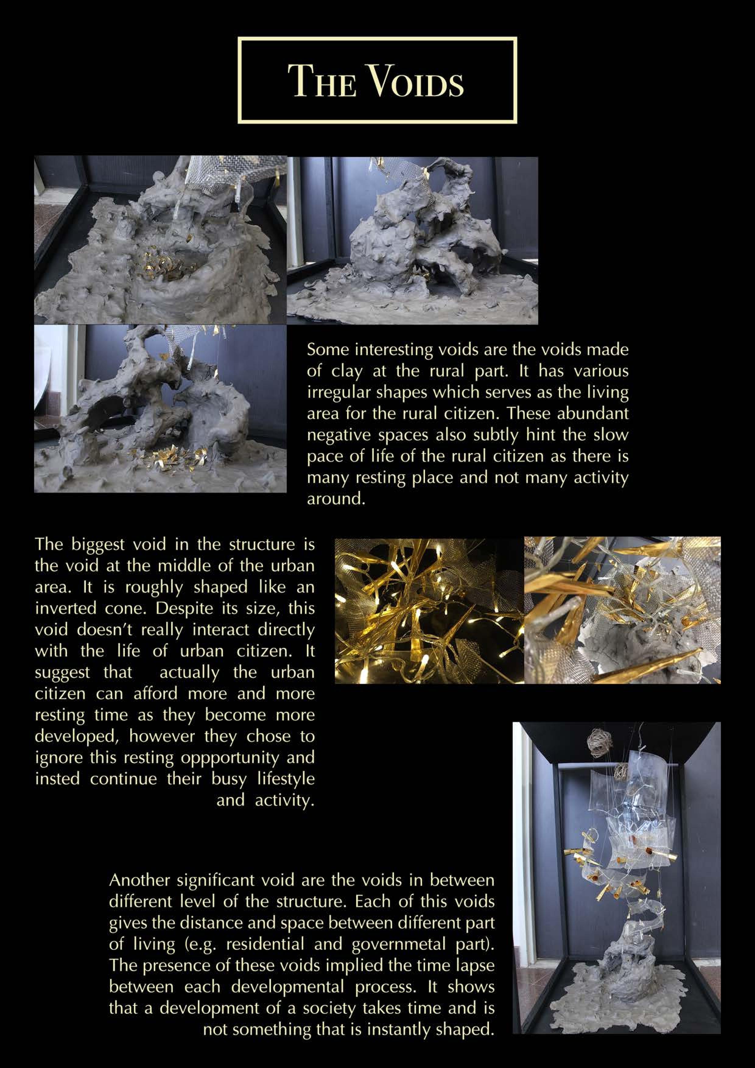
Together with Gloria and Gerald, we managed to finally create our final mood box and final model of our city: Kirithra!
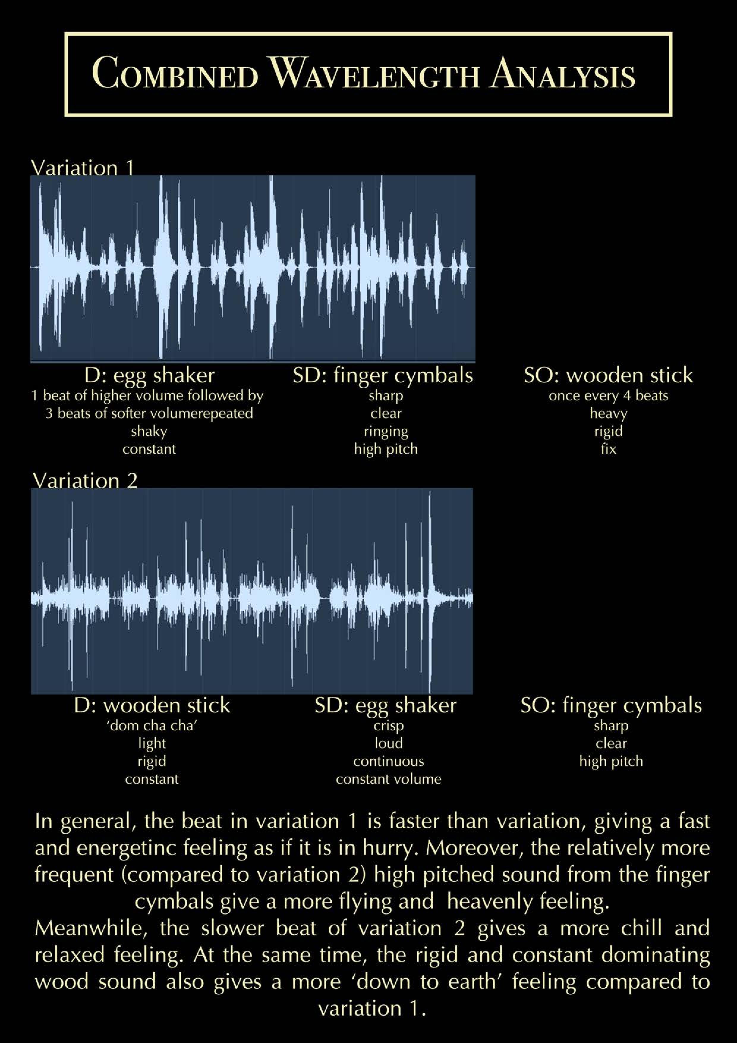
Here is the combined sound file (variation 1 to variation 2) :
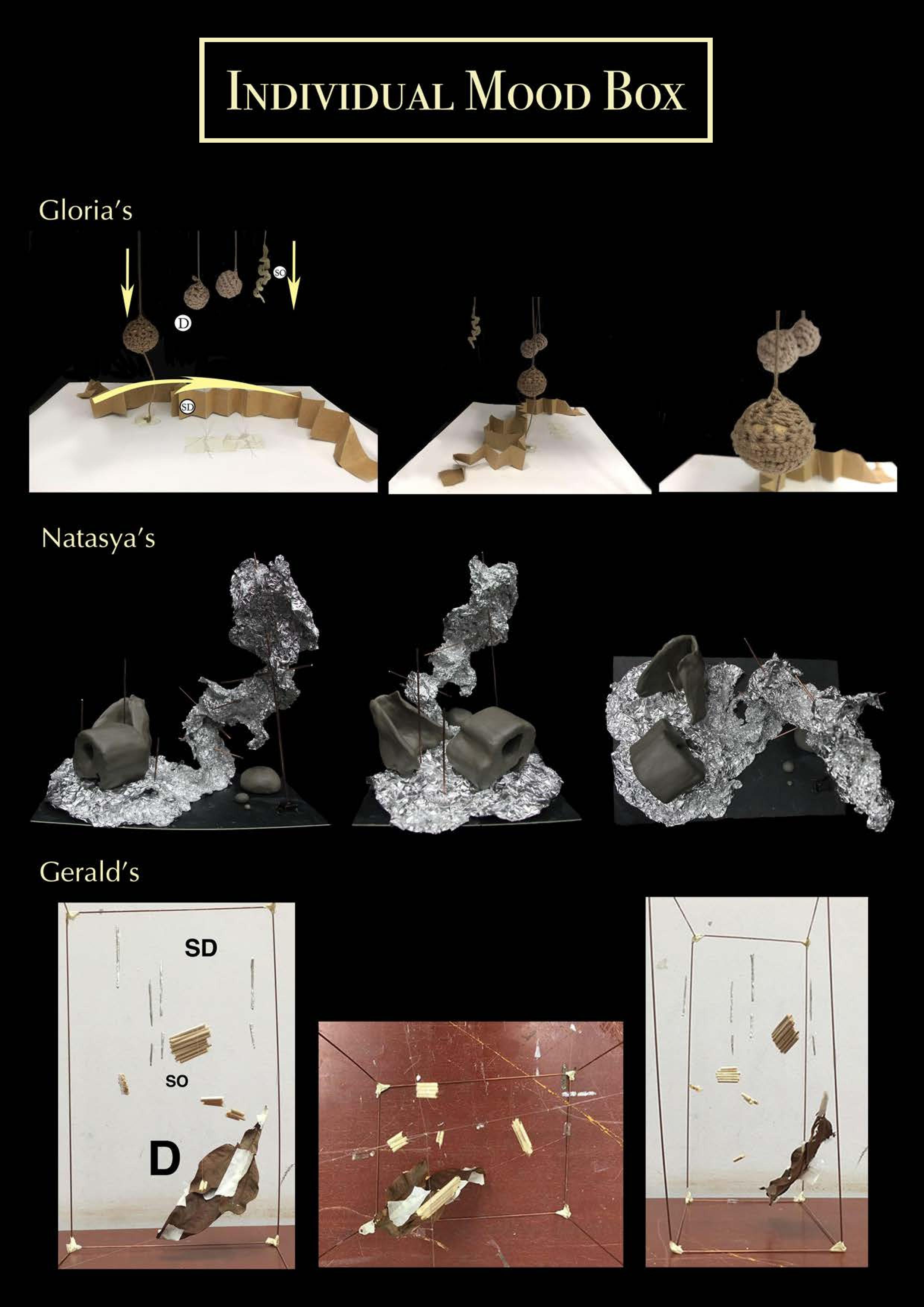
Here is the our Mood box and Final Model! (click g7_a_004b for pdf version) 😀
VOILA! So that was it! Hope you enjoy and learn something from it. This will be my last post on the bitter sweet journey of 3D Foundation I. Thanks for reading! :’)
Following up the previous 3D post about individual model, group B revised and revised and finally came up with our submission for 3D Final Model and PDF.
Here is some photo taken of the final model:
Artcard Model Front VIewArtcard Model Top ViewApplication Model Front View – BrightApplication Model Front – DarkApplication Model – Shadow
Then we decided to make the model neater:
Updated application model – FrontUpdated application model – SideUpdated application model – BackUpdated application model – Side 2Updated application model – ShadowUpdated application model – Shadow 2
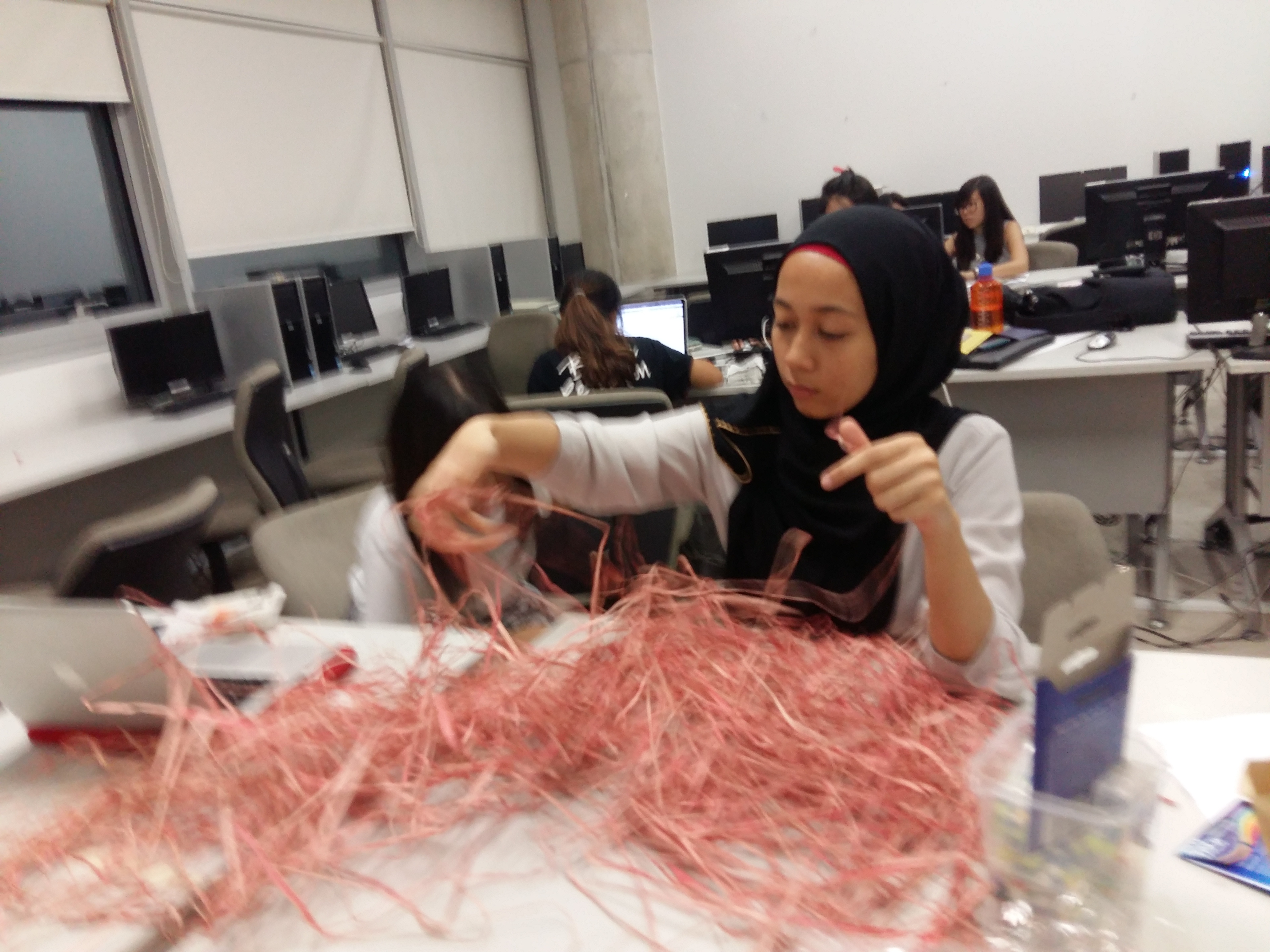
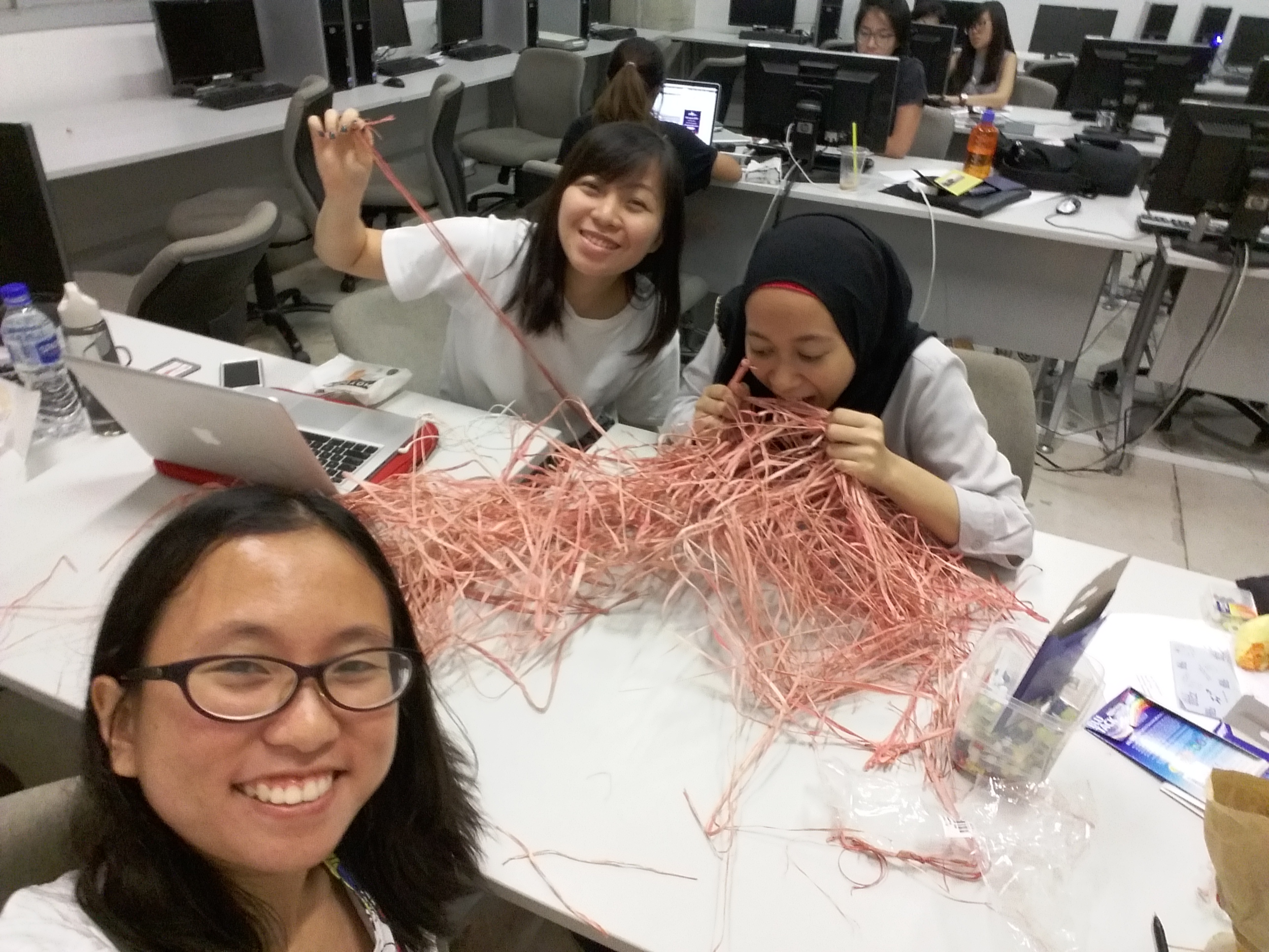
Here is some photos of us preparing for the Application Model:
Tools and Materials
Here is our PDF:
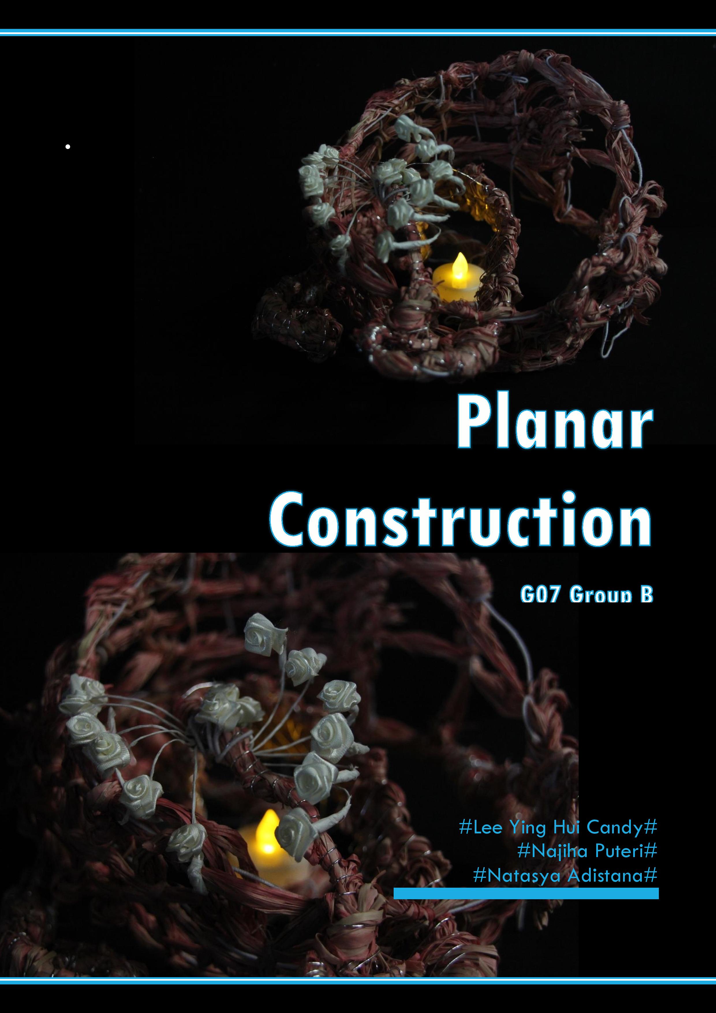
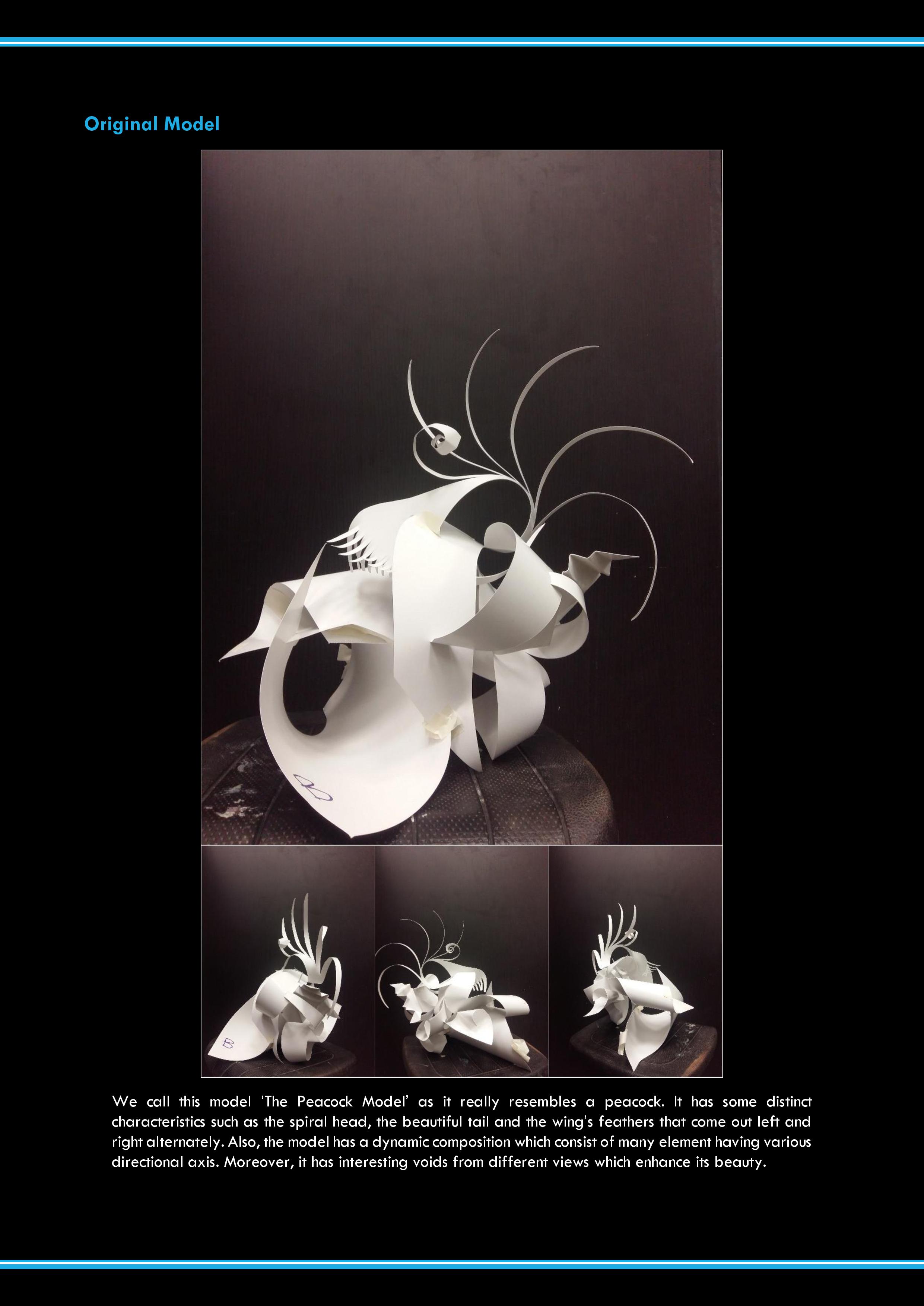
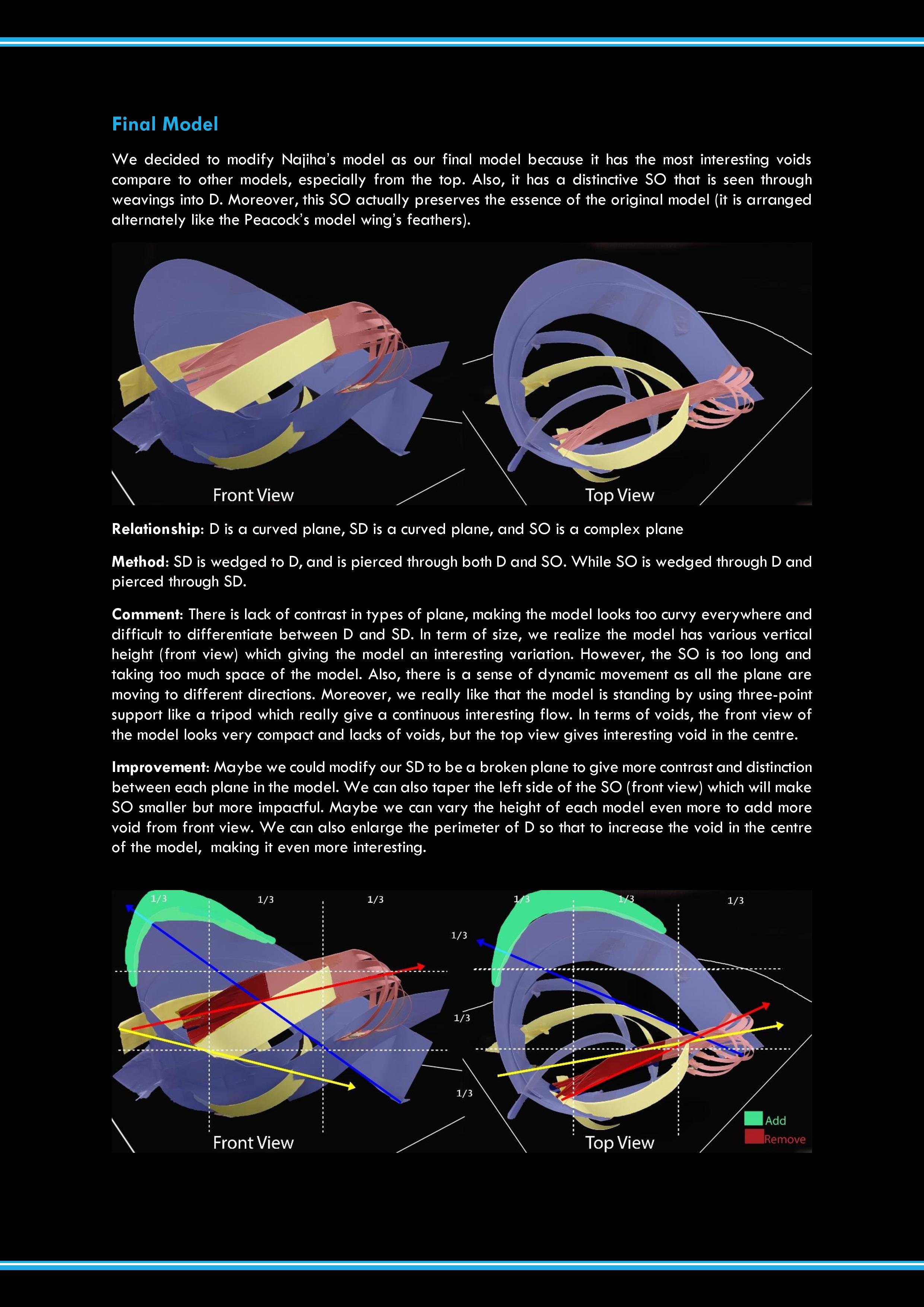
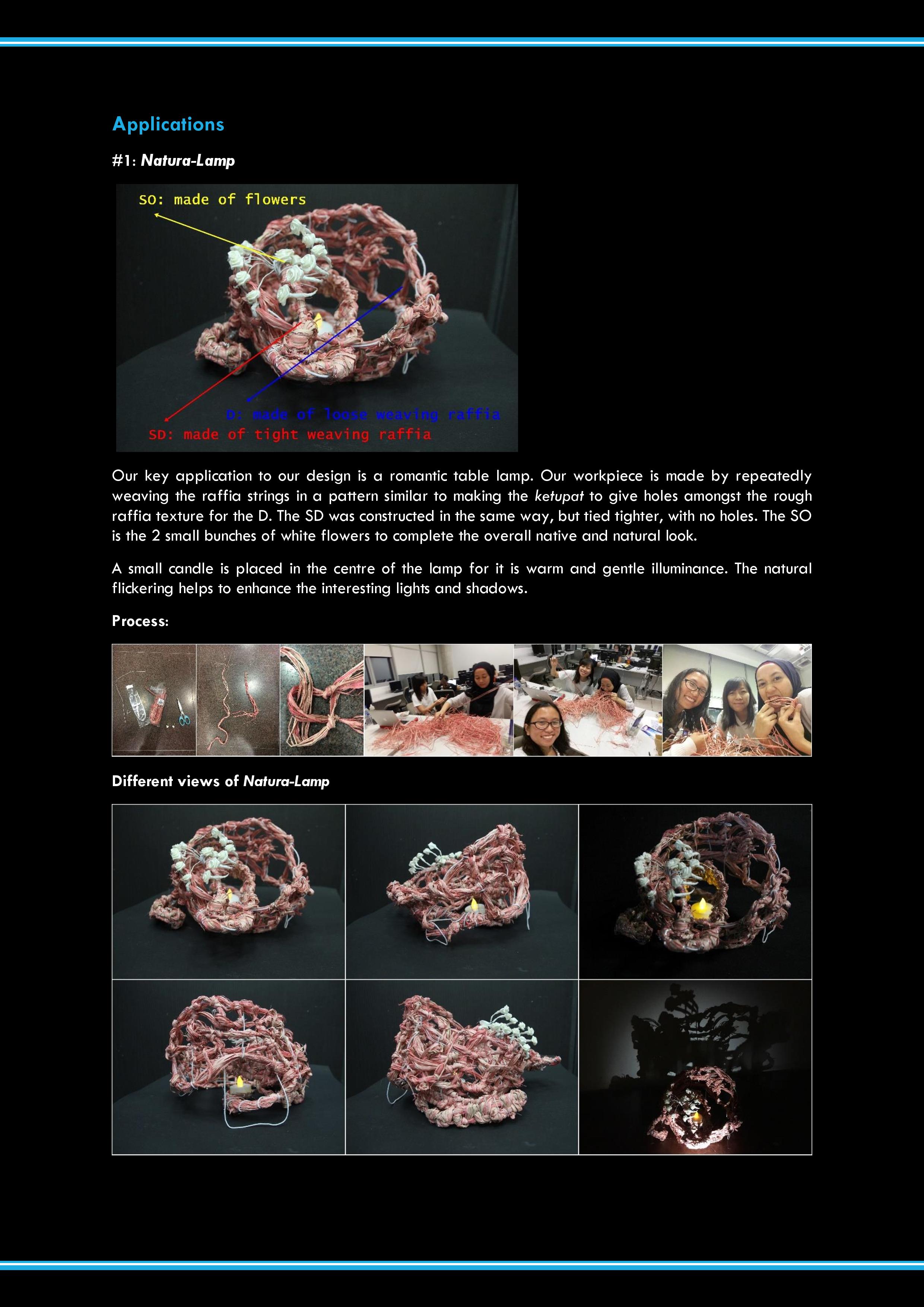
PDF cover pagePDF page 1: Original modelPDF page 2: Individual model inspired by original modelPDF page 3: Final model and analysisPDF page 4: Application 1PDF page 5: Application 2 and 3
So below is group B (Candy, Najiha, Natasya) members’ individual model for the simplified version of our Peacock Model.
Individual Models
Candy’s ModelNajiha’s ModelNatasya’s Model
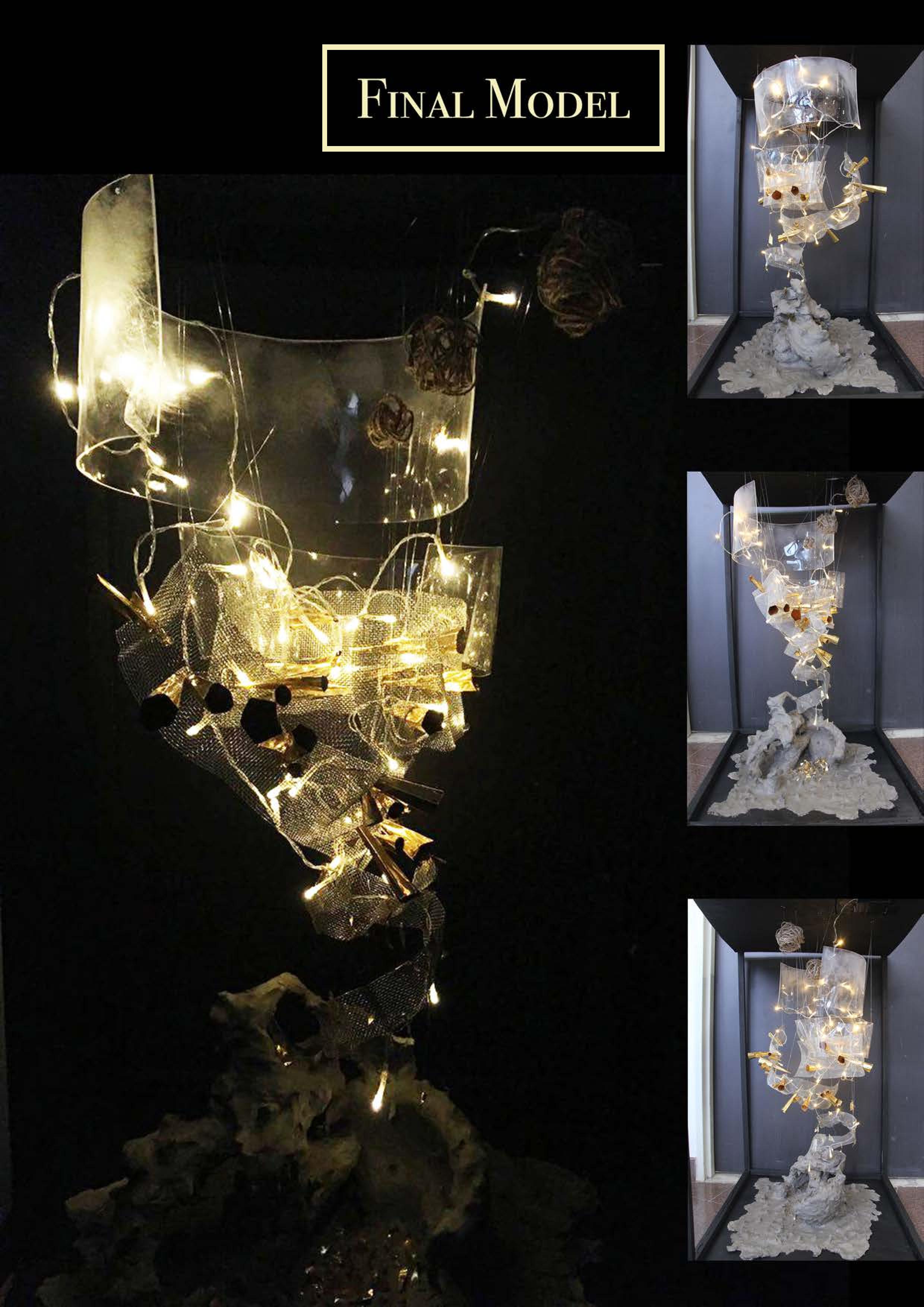
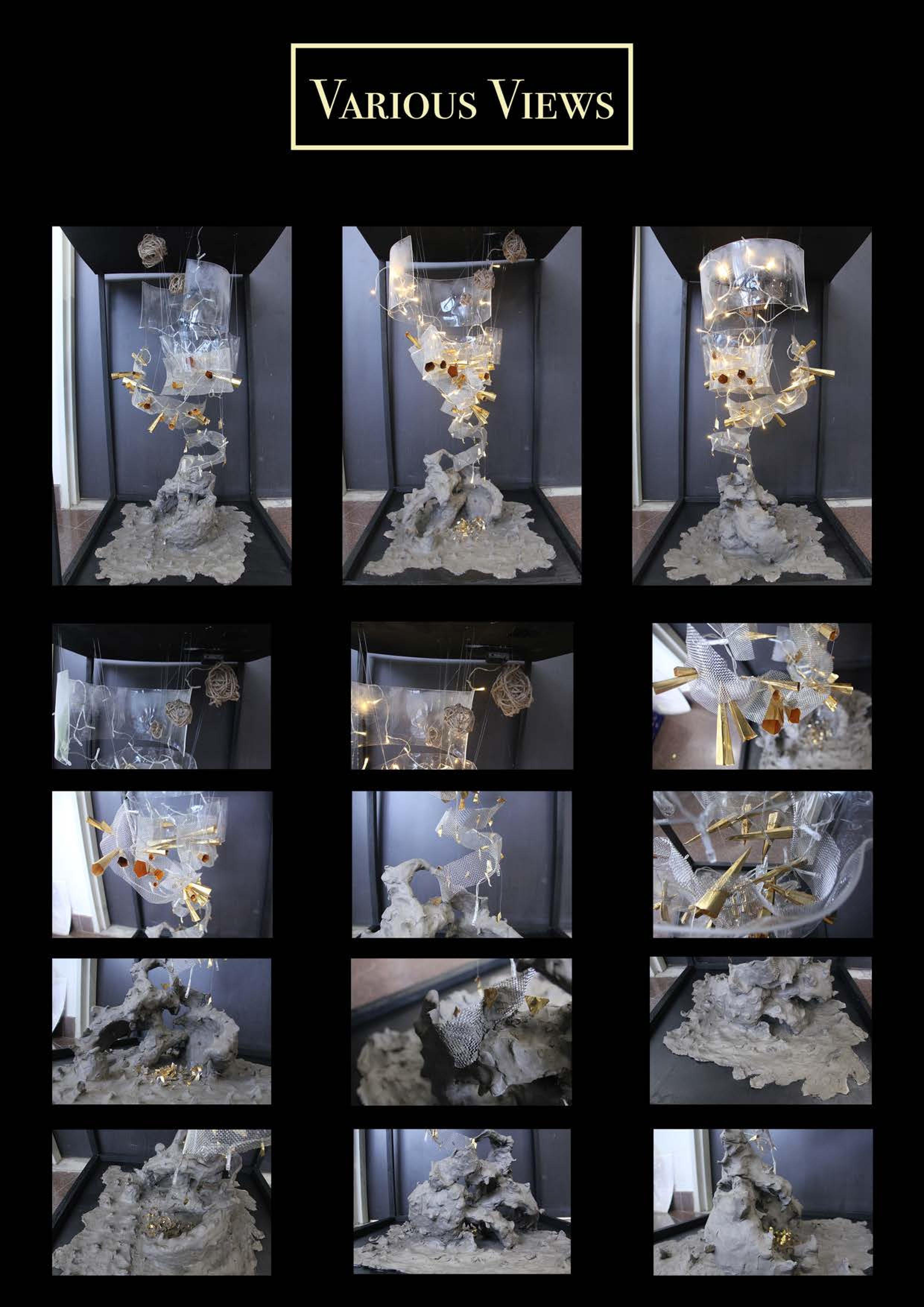
Final Model
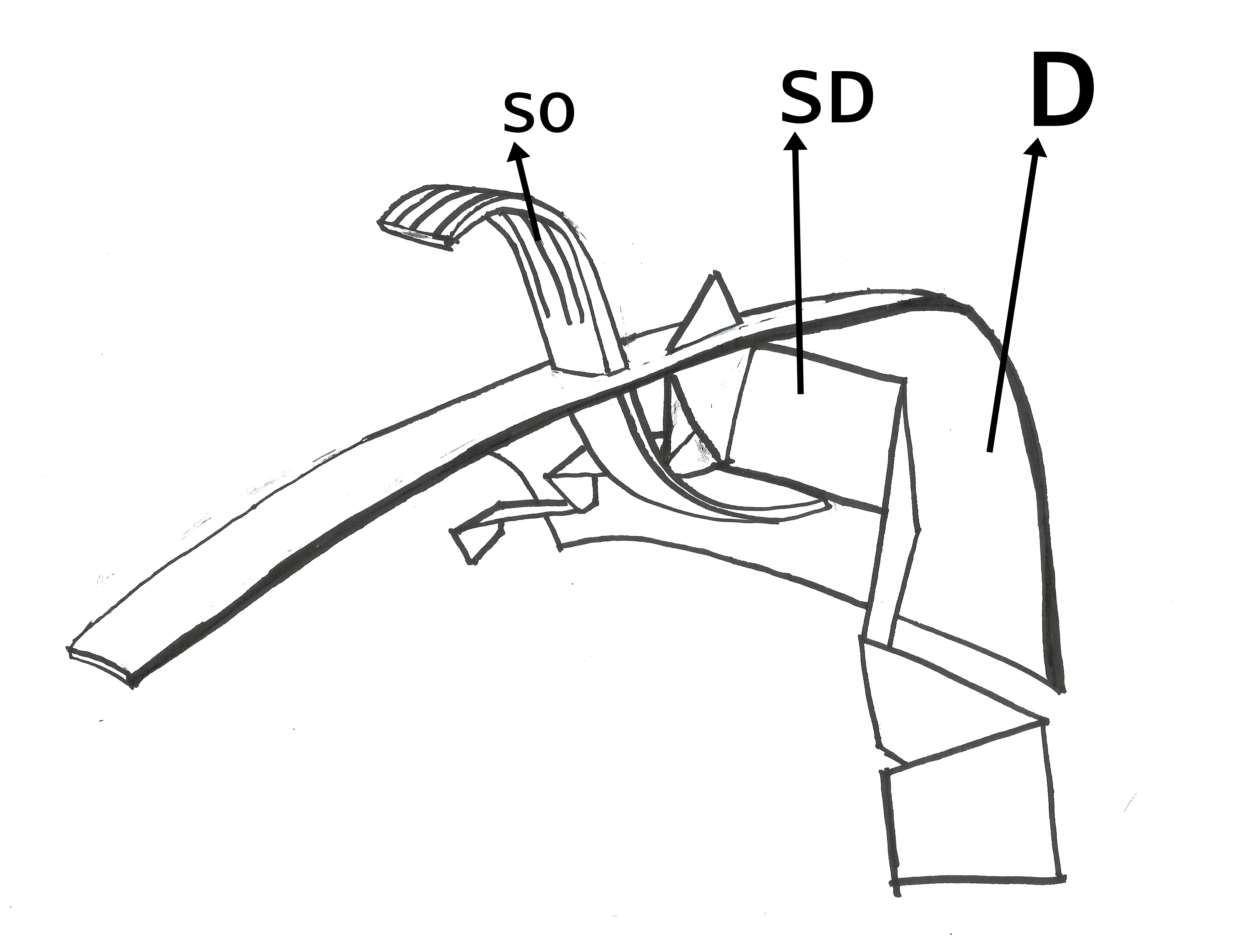
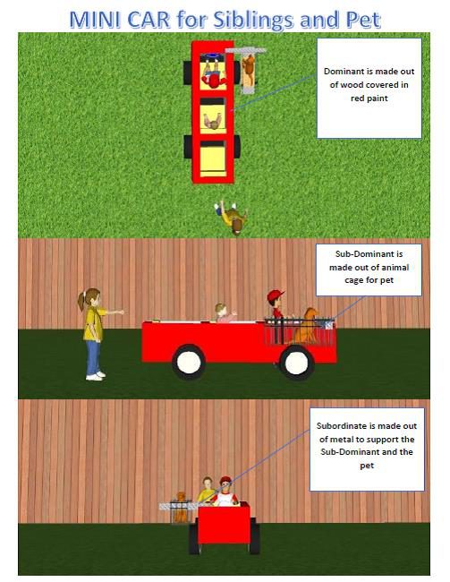
For our final model, we decided to combine all three models. The Dominant is taken from Candy’s D, Sub-Dominant of Natasya’s SD and Subordinate of Najiha’s SO.
This is roughly how it will look like followed by the improvements we will do when we make the final model.
Group B final model sketch
Dominant: A curved plane from Candy’s D. Comment: It is not so dominating as the cluster of activity from SD and SO occupy almost half of the area and because D is vertically the shortest also. Improvement: We will make the D a lot bigger (vertically) so that the cluster of activity will only occur at the right one-third area. Also, it will increase the void and make D more interesting. Also, maybe we can adjust the shape of the part that touch the base to the be more pointy so that it act like a tripod instead of being a wall.
Sub-Dominant: A broken plane from Natasya’s SD, some part pierced through D. Comment: From above, the SD may look like from the same family as SO Improvement: We will adjust the SD to have more presence than SO from top view. Also, to make SD more interesting, more part can be pierced through D.
Subordinate: A bent plane from Najiha’s SO, pierced through D at the middle and cut to at the top part to keep the signature from the Peacock Model. Comment: It has an interesting shape that cut the D void. However piercing it at half making it looks common. Improvement: We will adjust the positioning of SO to make one-third only being pierced instead of half.
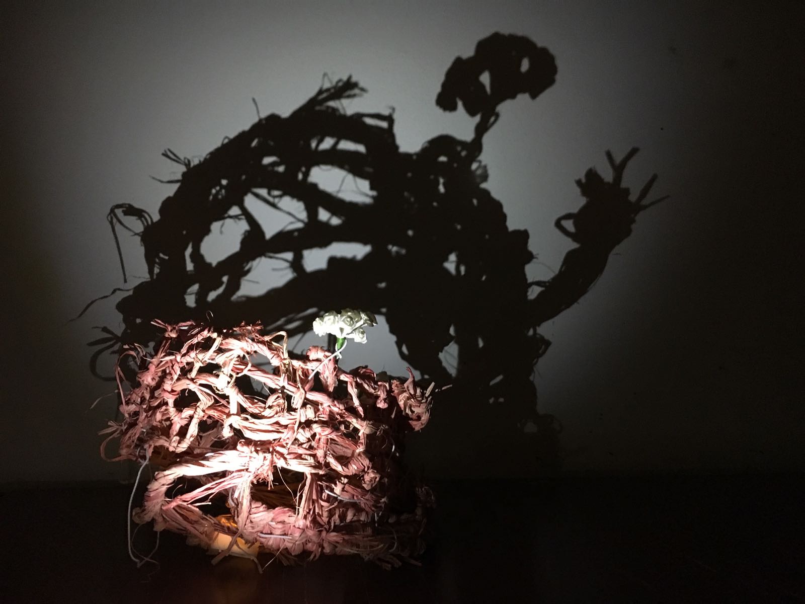
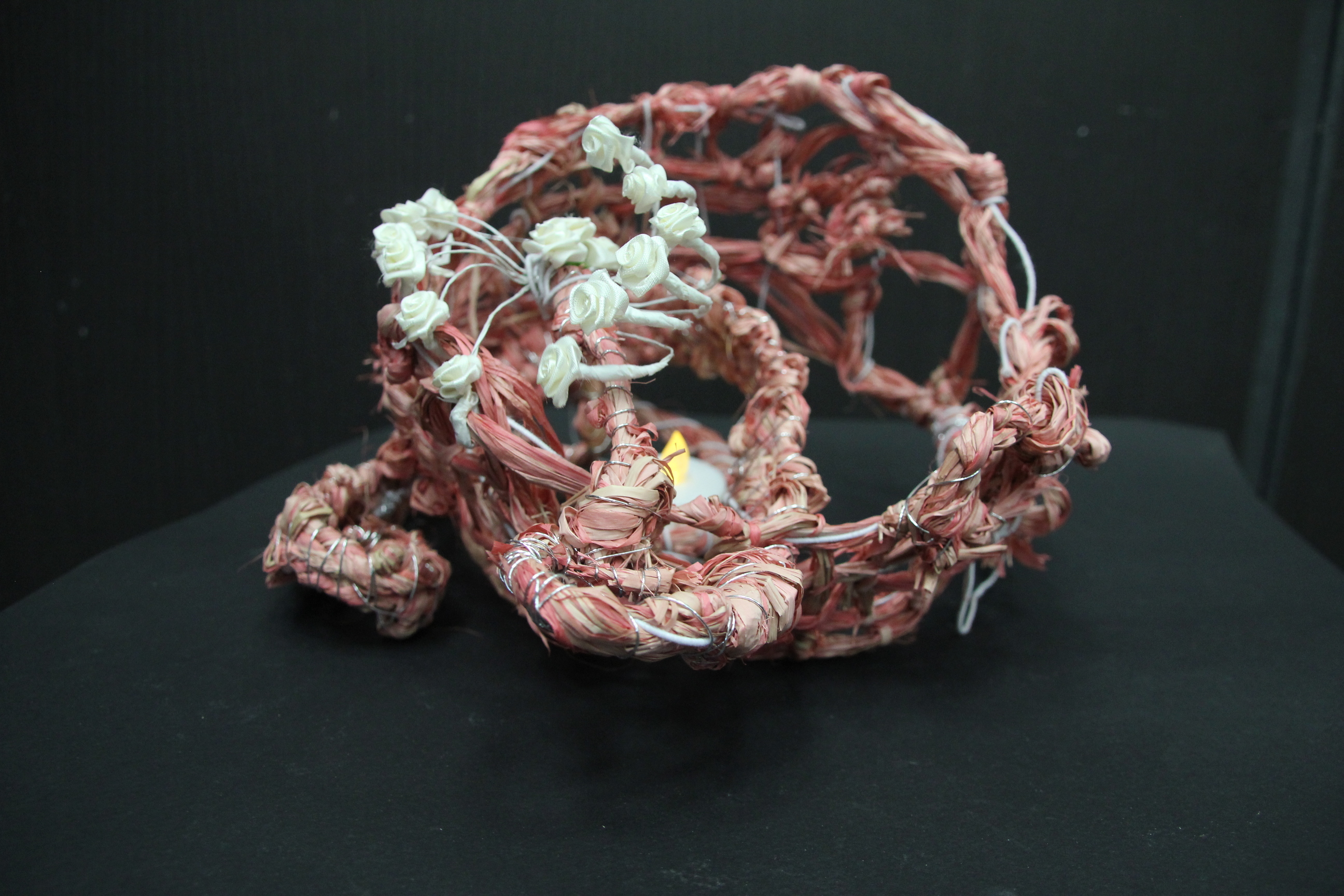
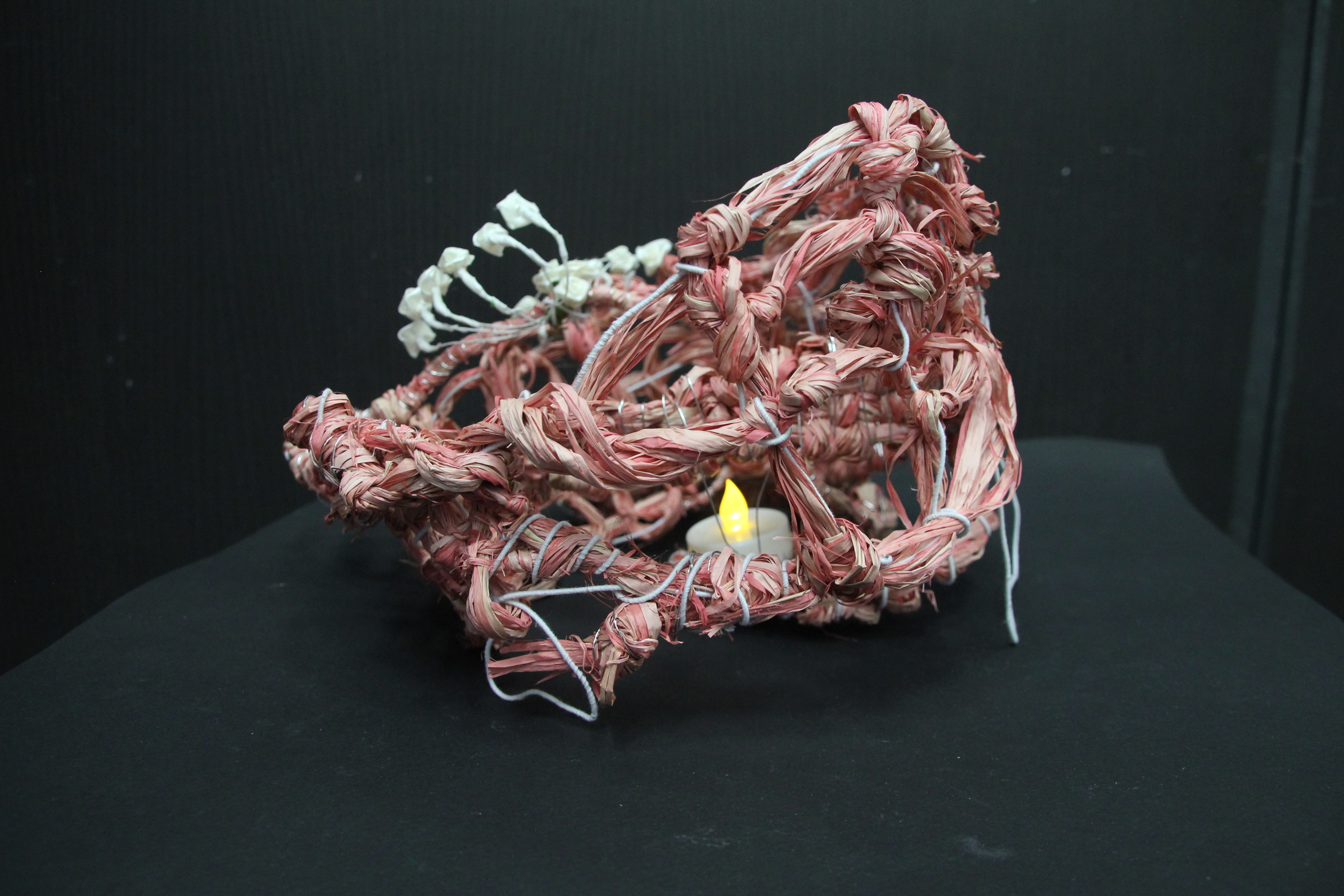
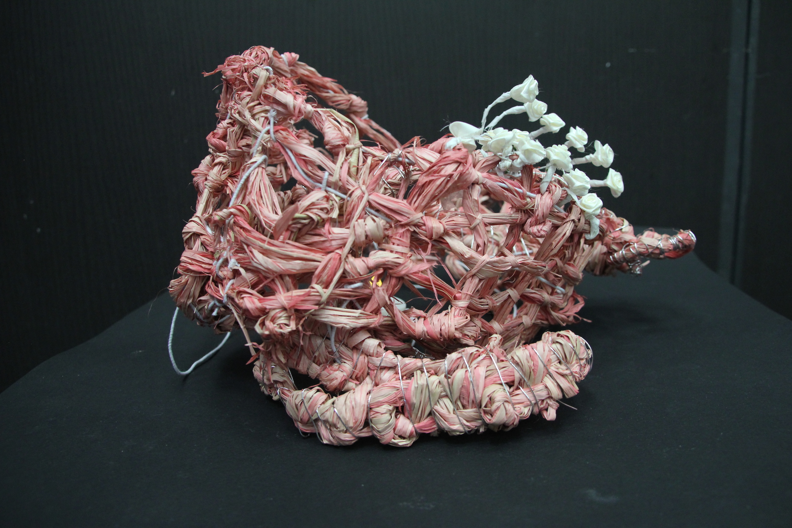
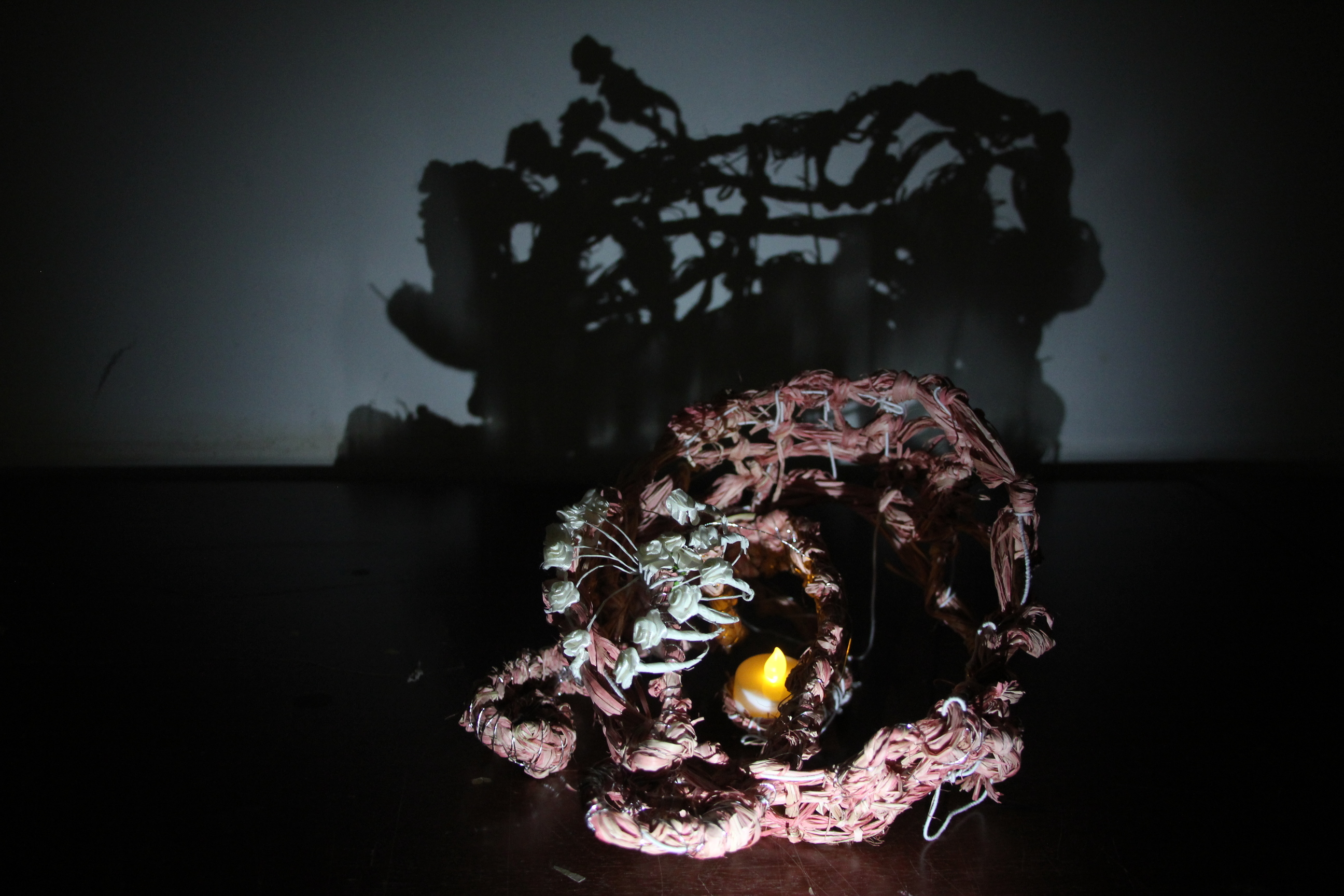
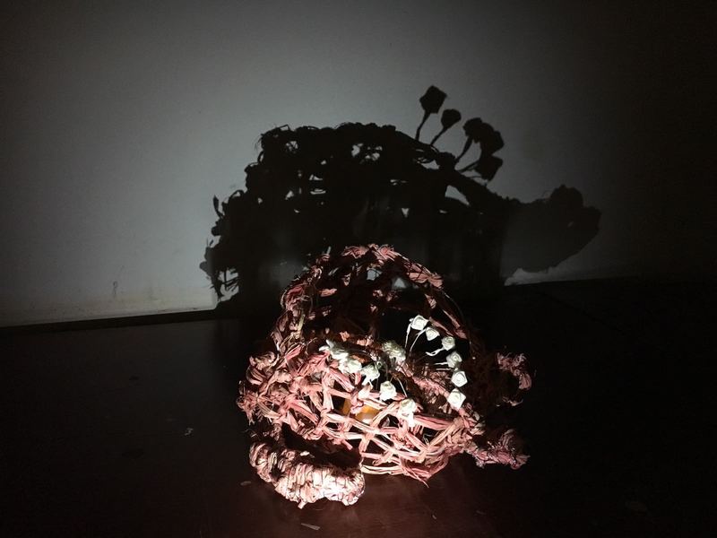
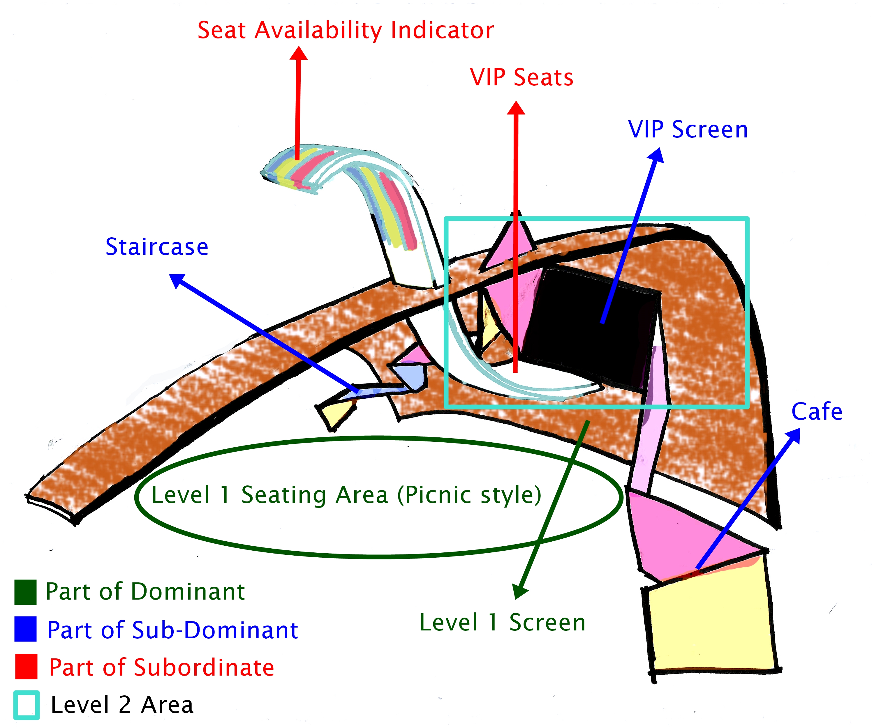
Final Model Application #1: The Seats that Float
The Seats that Float
It is a 2 level night outdoor movie screening exhibition.
The Dominant is used as the main building as well as the screen for level 1. The people who watch in level one is watching in a picnic style (seating on a mat on grass field).
While the Sub-Dominant is for staircase to go to level 2 as well as screen for the VIP Screening at level 2.
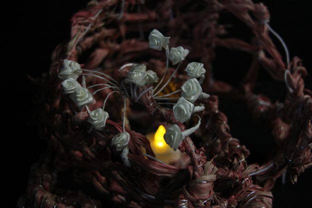
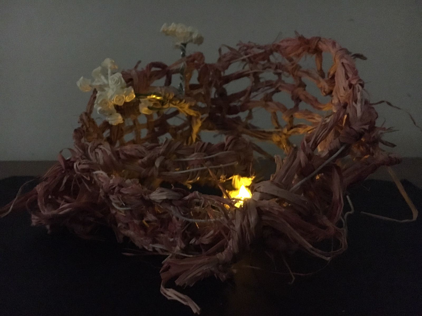
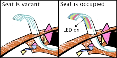
Lastly, the Subordinate has two part. the bottom part is for the VIP seating which is open for everyone but has limited space. The other part is VIP Seat Availability Indicator. Basically the LED light will turn on when the seat in VIP Area is occupied. It is to indicate to people outside whether there is still space in VIP Area.
Seat Availability Indicator
Proposed Materials
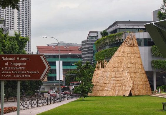
For real application, Dominant is made of straws, inspired by an exhibition at National Museum in 2013.
The Exhibition building that inspires us
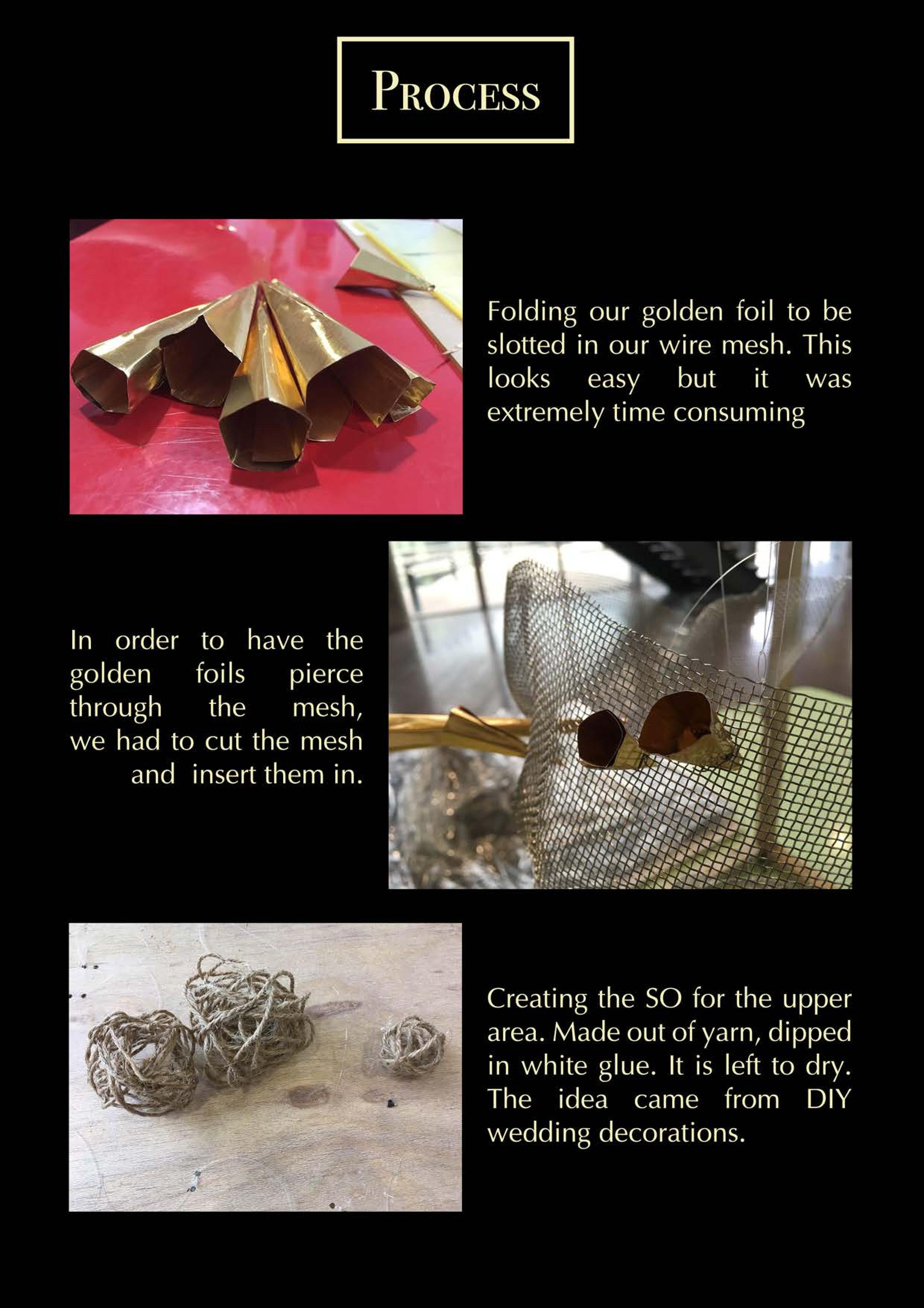
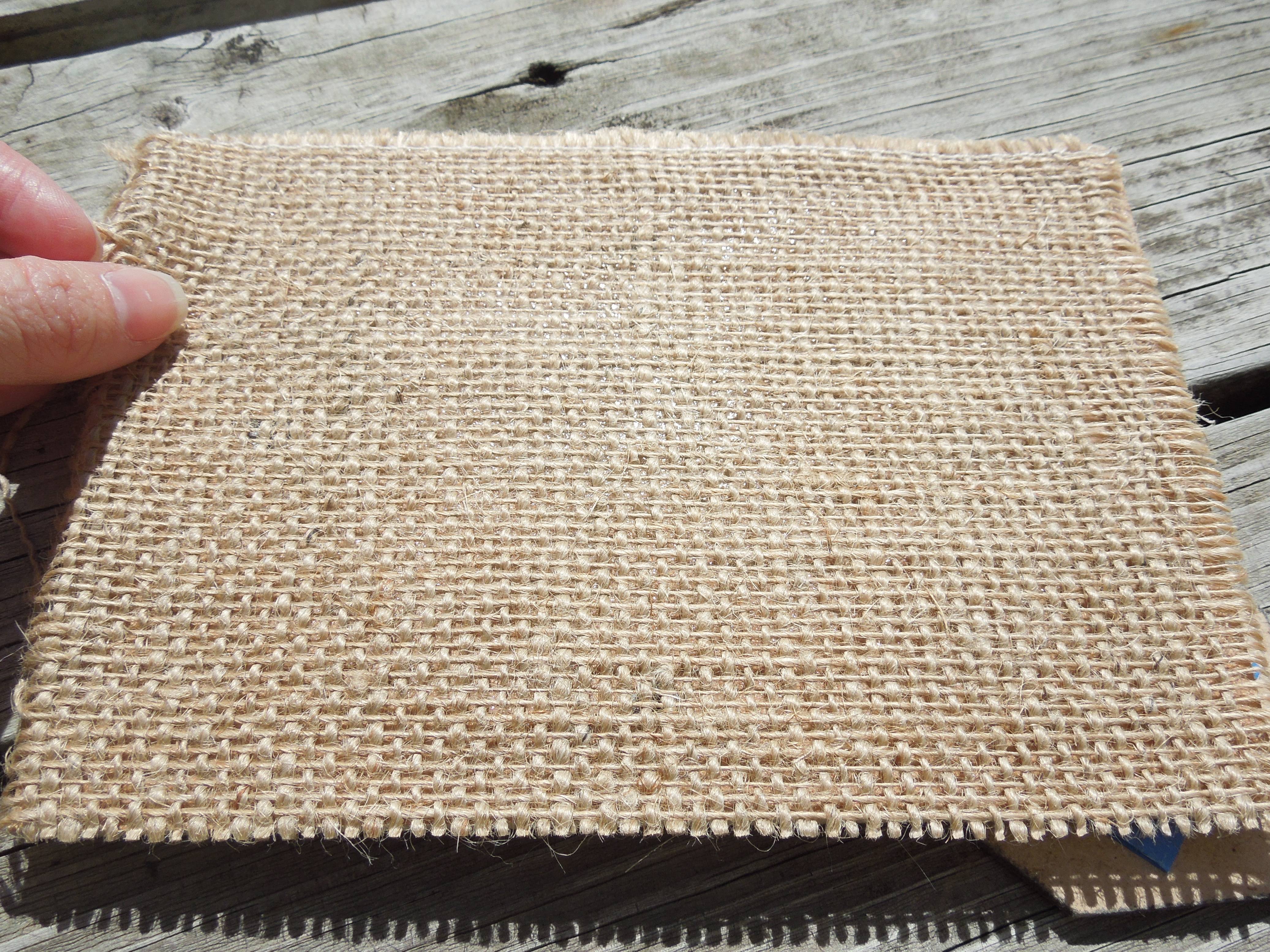
For the model, we are using wire as the skeleton, covered by a piece of burlap.
Burlap
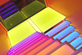
For the Sub-Dominant, the real application is made of glass treads with a multiple colors LED lighting, preferably dark colour.
Glass treads staircase
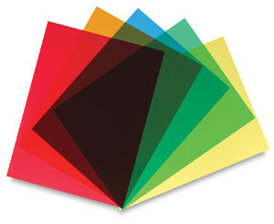
While for the model, we are using colorful acetate papers.
Acetate papers
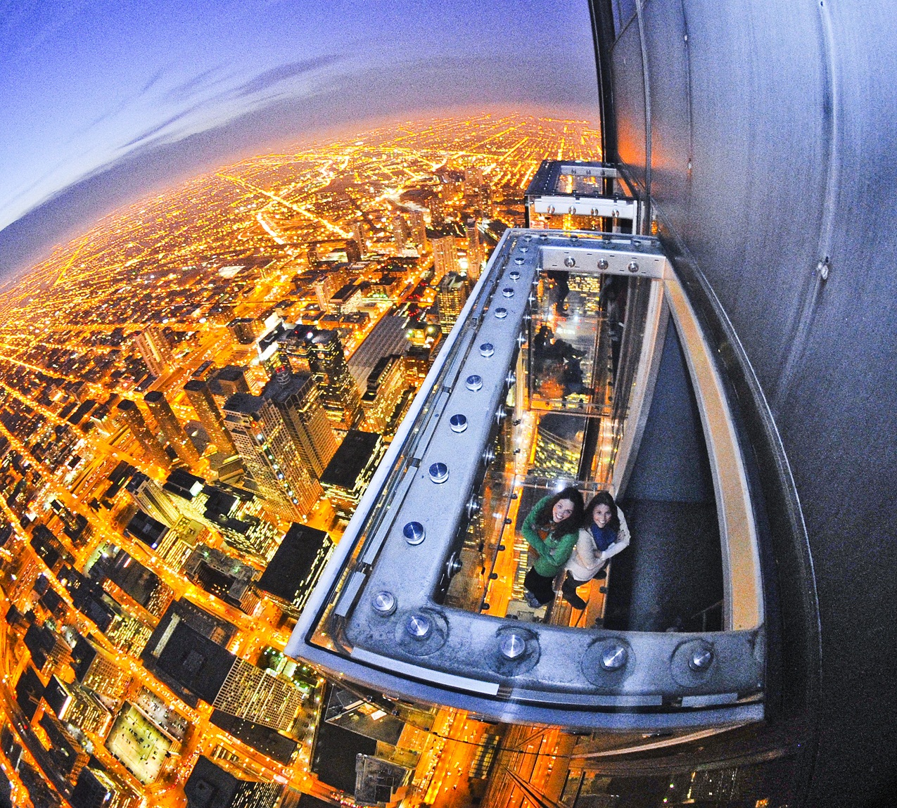
For the Subordinate, the real application is using fully tempered clear glass, like those used for skyscrapers’ skydeck.
The Ledge of Chicago, a skydeck.
And for the model we are using thick a PVC matte sheet.
PVC Matte Sheets
Thank you! Really appreciate your comment and feedback 😀
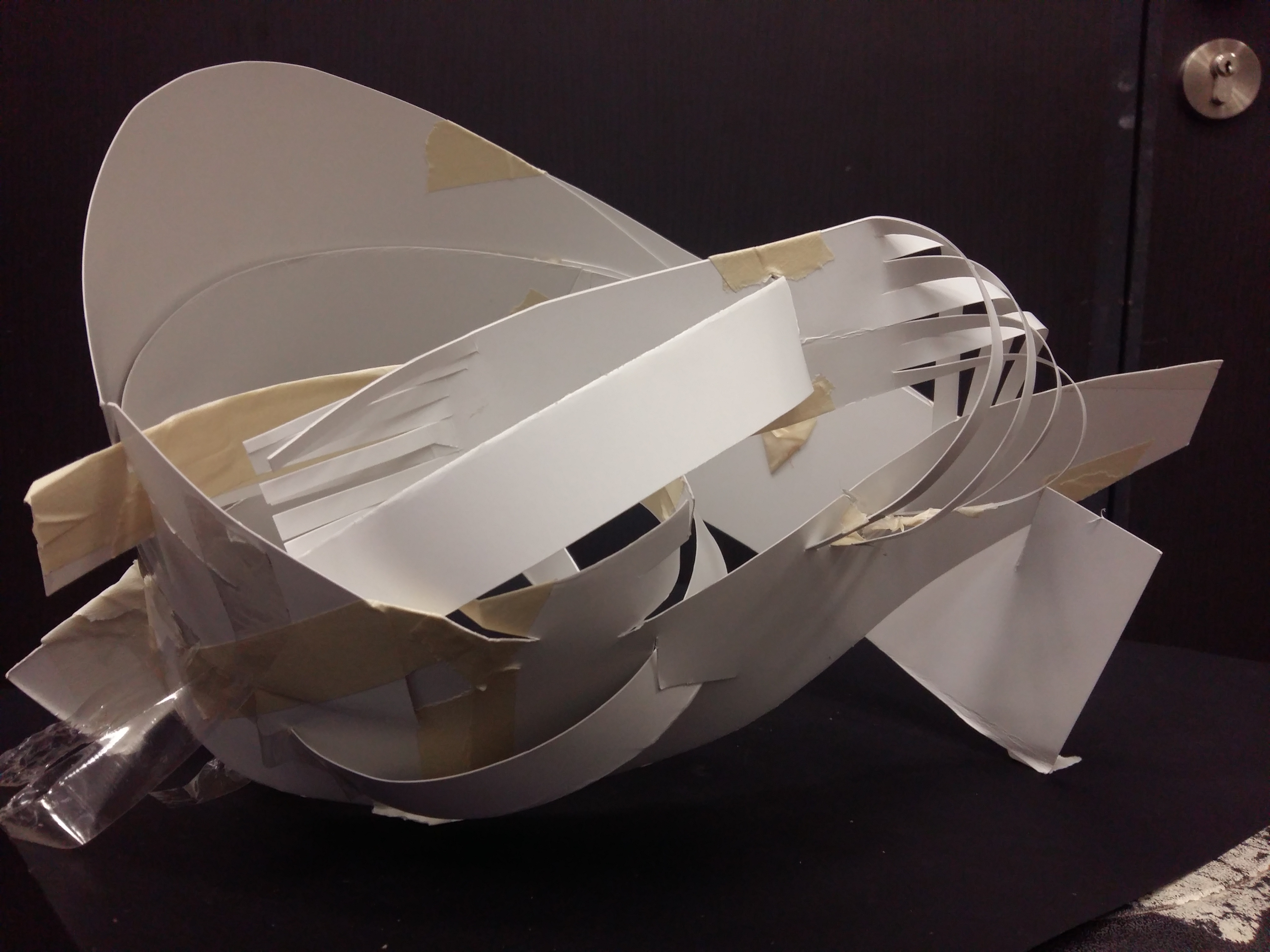
So for 3D class I chose the improved version of my Model 1 in my previous 3D post to be my Final Model!
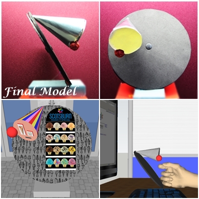
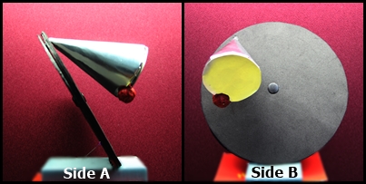
Photo of my Final Model:
My Final Model from different sides
Relationship: Cylinder is Dominant (D), cone is Sub-Dominant (SD), and sphere is Subordinate (SO)
Method: Wedging between SD and SO
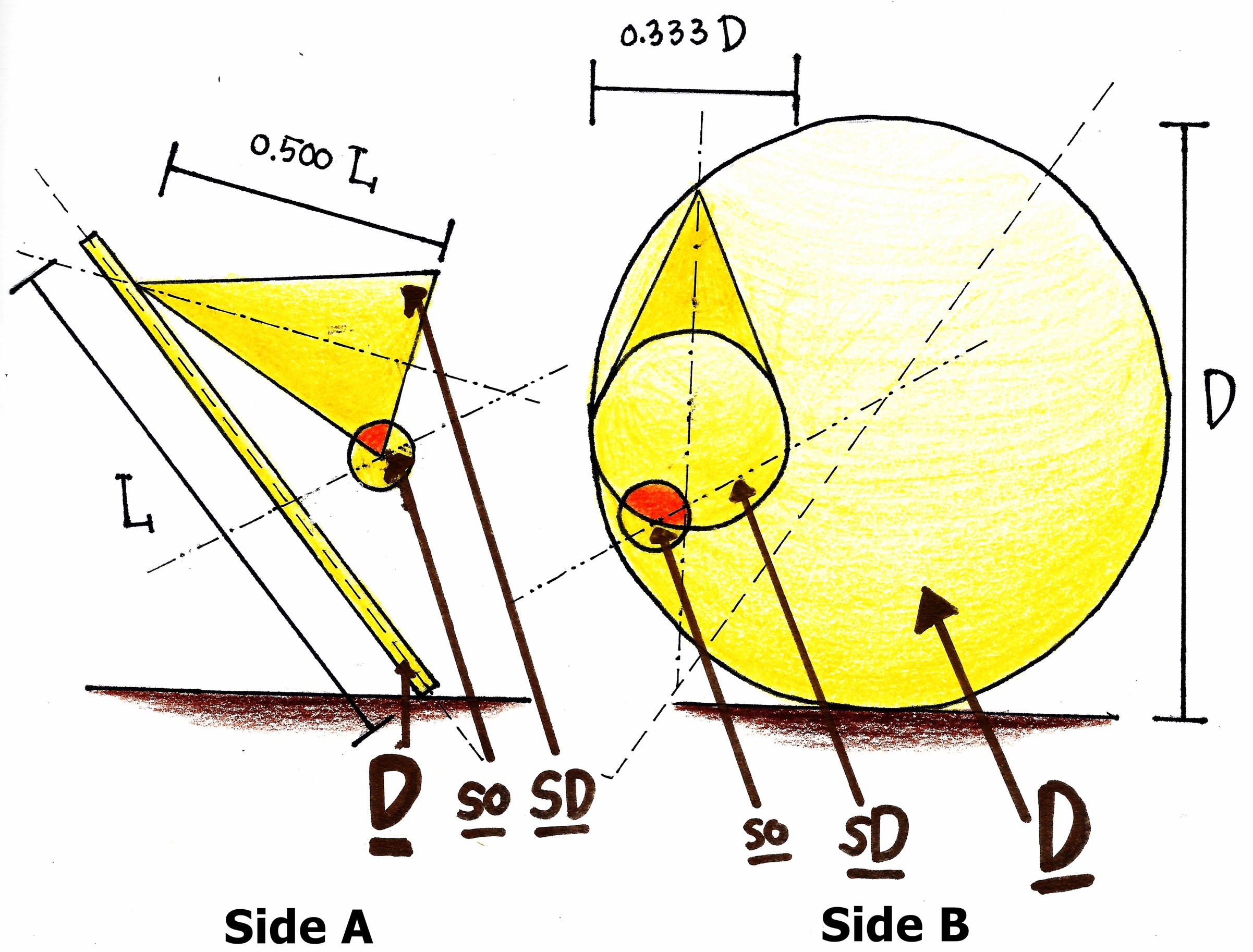
Proportion and Rhythm Inherent: Sphere has the smallest diameter, around one-third of cone diameter. While the cone has diameter about one-third (~0.333) of cylinder (disk). So, the cylinder has the largest diameter. Comparative: Cone is the greatest in mass, followed by cylinder then sphere. Overall: Cone has a precarious balance on cylinder while the sphere is dependent on the cone.
Comment: There was no much changes made to my Final Model. The main change is the addition of the Dominant diameter hence area of cylinder. However this small change really alter the impression of the model. At first, there was relatively high tension between axes of D and SD, and the change has significantly reduced this tension, creating an even better flow. Also, despite its precarious balance, the model looks natural and firm.
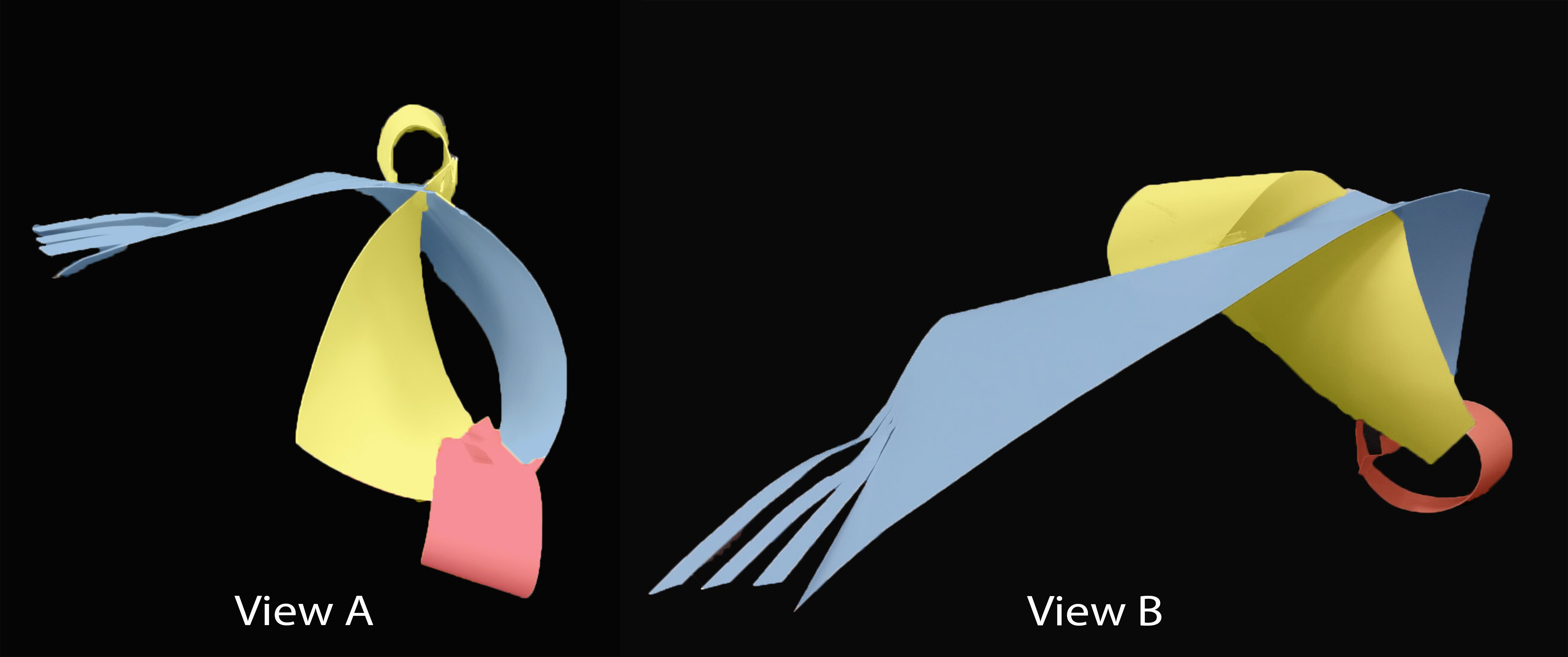
Also, this is the 2D Sketch Analysis of the Final Model:
Final Model 2D Sketch Analysis
From both sides it is shown that the Dominant, Sub-Dominant and Subordinate in my Final Model is constant throughout.
From side A, as the length of SD is around half D, I think I should pierced through the SD to move it up and occupy more of the top part of the D.
From side B, the proportion between D and SD look balance and good.
Then, I will also move the SO outward to make it visible from the other side of the D.
2D Sketch of Improved Final ModelLegend for 2D Sketch
And bellow are the applications of my Final Model!
OYIC!! – Application of Final Model #1360-Cube Joystick! – Application of Final Model #2
And last but not least, a short video of 360-Cube Joystick on Mario Kart:
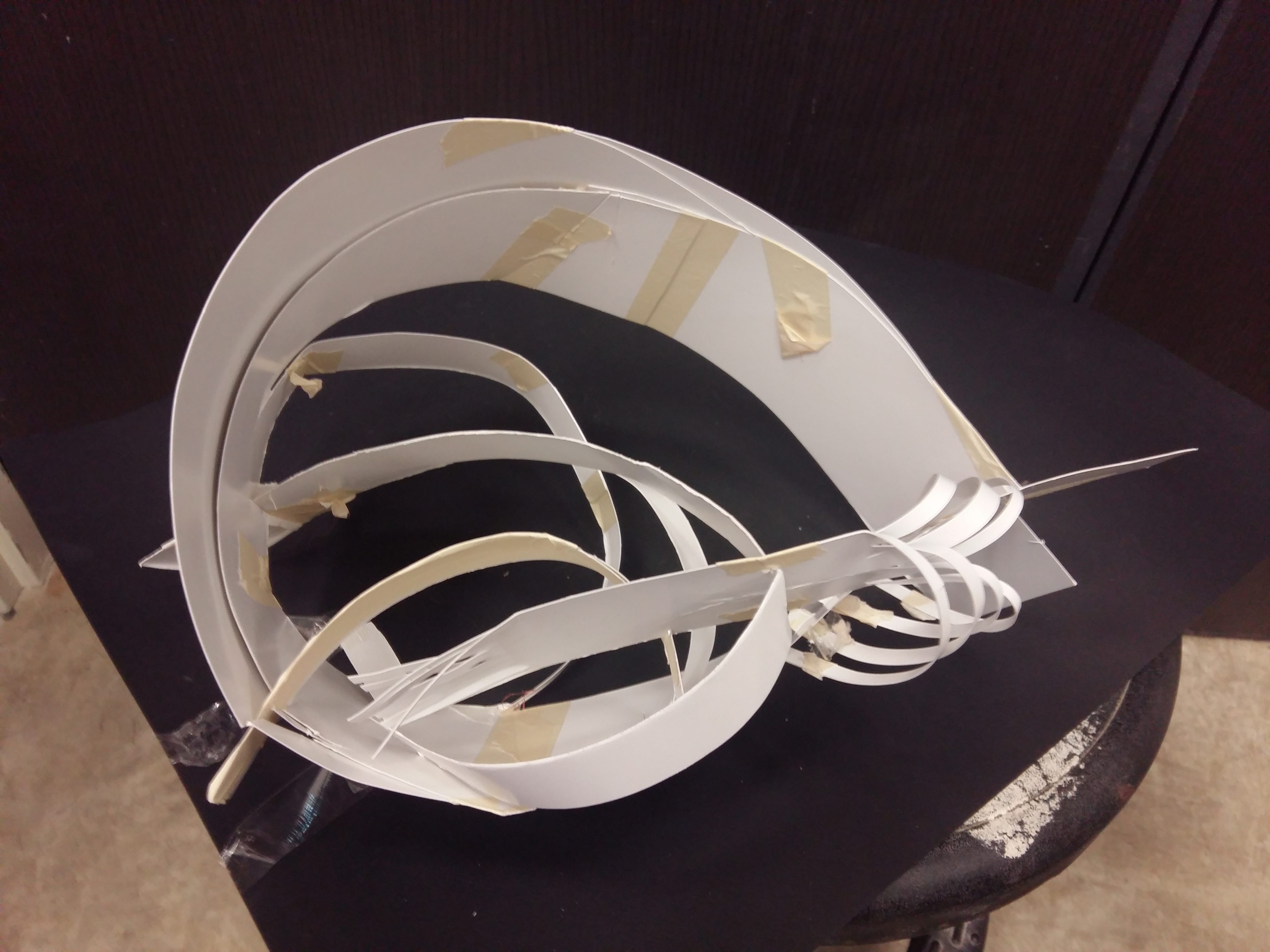
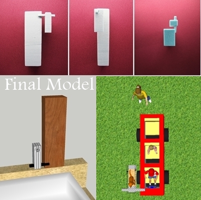
Hi! So I have chosen my Model 3 in the previous post to be my Final Model. Yeay!
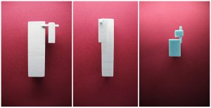
So here is the photo of my Final Model:
My Final Model from different sides
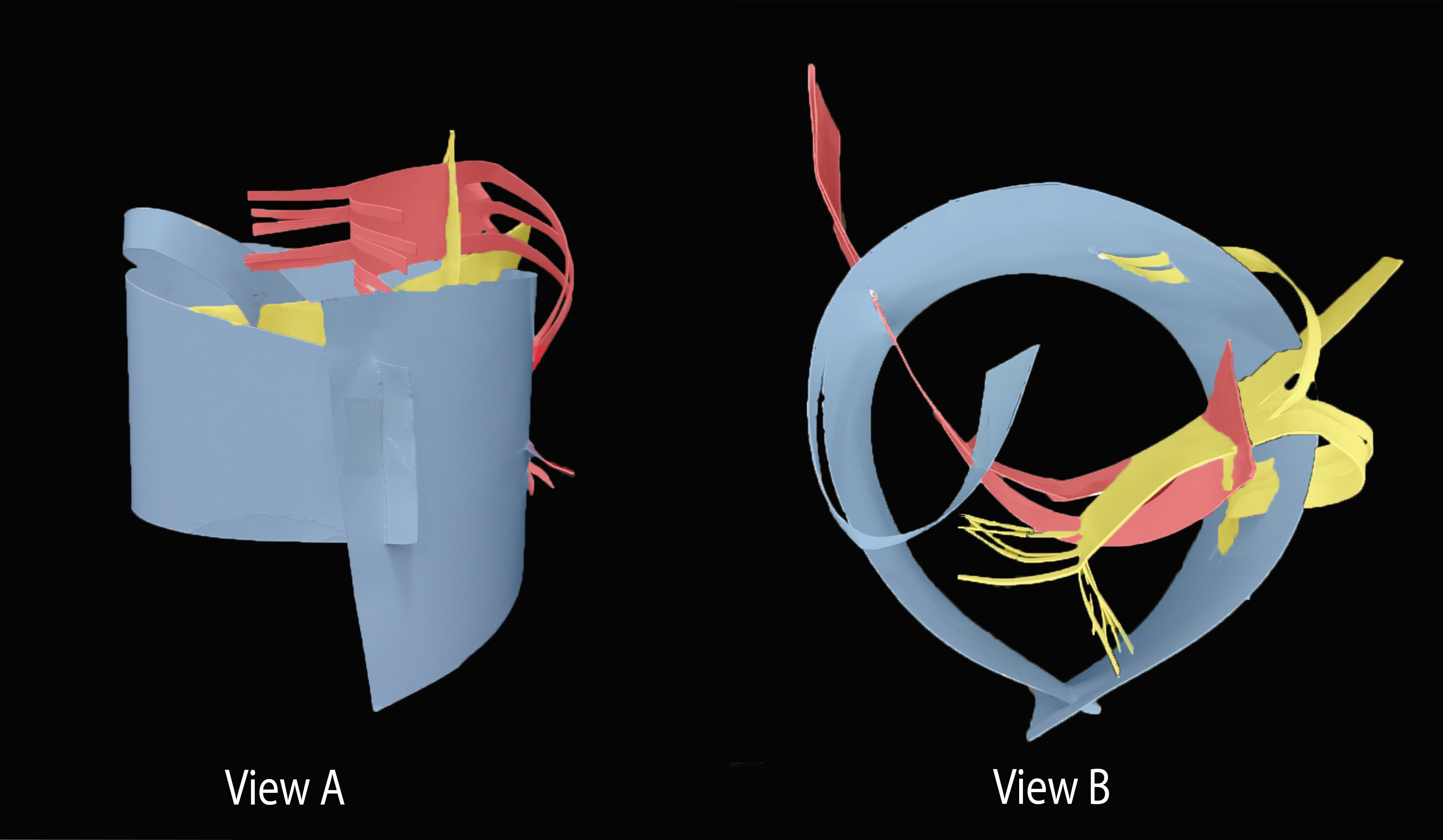
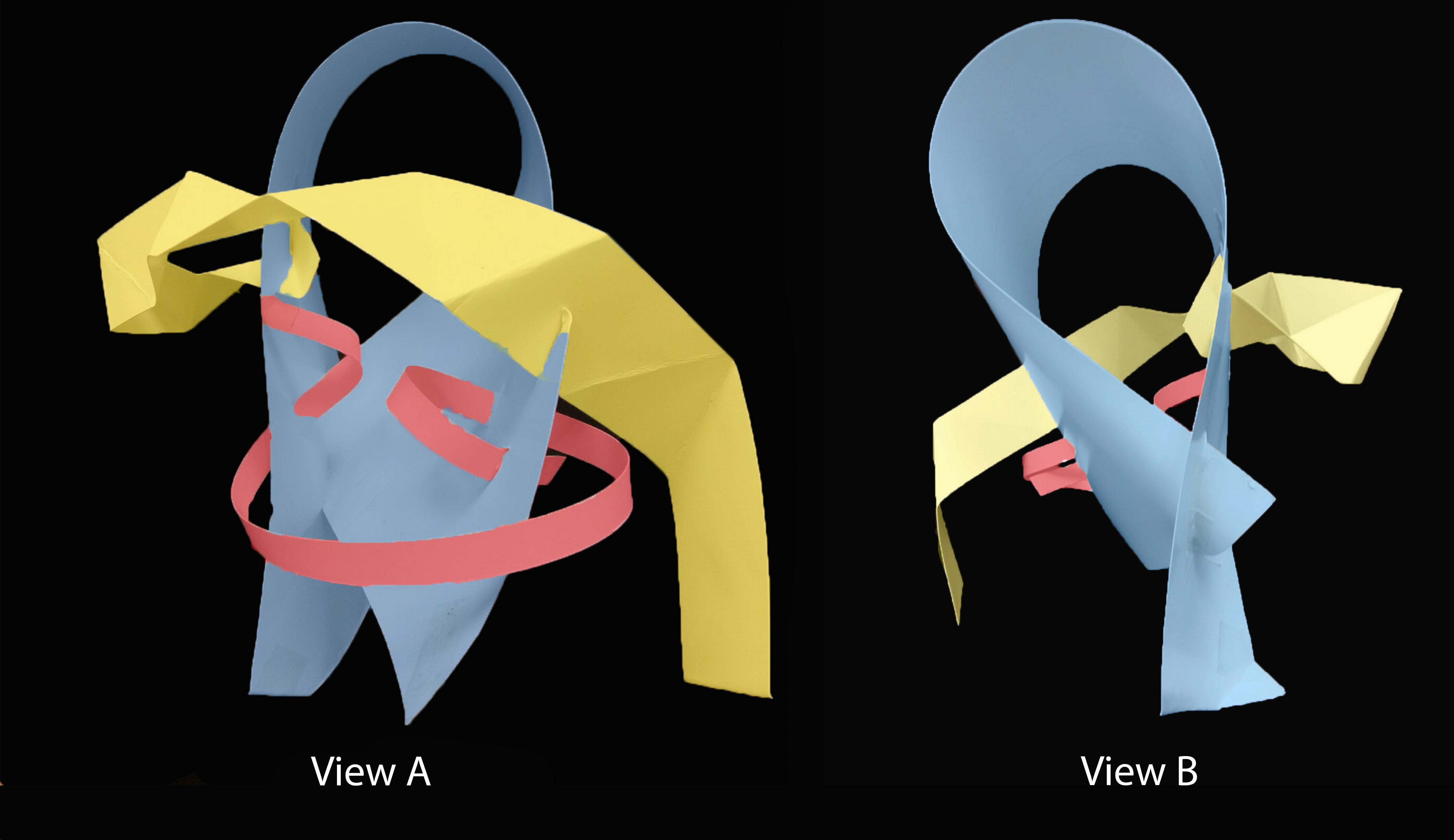
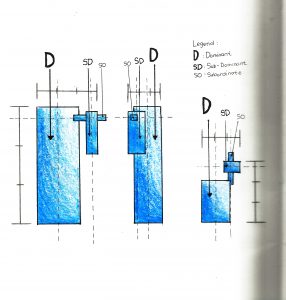
Then I also made the 2D sketch analysis for this model.
My Final Model 2D Sketch Analysis
At first it looks okay as from all sides it is shown that the Dominant (D), Sub-Dominant (SD) and Subordinate (SO) in are consistent throughout. However there are some things that can be improved on:
Referring to first side shown, the vertical length of SD looks similar to the horizontal length of D. Hence the D vertical length need to be longer, which will positively make the D more dominant as well.
Referring to second side shown, the position of SD should be move more to the left so that it will be even closer to the area between half and one-third.
Referring to the third side shown , the vertical length of SO looks similar to the horizontal length of D. The vertical length of SO need to be shorten differentiate it, but be careful to not be as short as the horizontal length of SD.
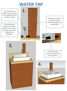
And below are the applications of my Final Model!
Water Tap – Application of Final Model #1Mini Car – Application of Final Model #2


 I learnt to experiment a lot during this exercise! It was actually fascinating to try out different sounds 😀