Polishing the final frames

This is a continuation from previous posts.

Part 0 (Ideation)

Part 1 (Modelling, texturing)

Part 2 (Sand simulations)

Part 3 (VFX)

Part 4 (Volumetric Lighting)

This is Part 5 and the post will cover Polishing – the final touches to achieve a quality finished render.

We also did something cool with our scene to allow it to do this:

Above is me changing the aspect ratio, and the camera just changes instantly. All this is happening while our video is rendering.  At the end, we’ll mention how we made use of the game engine’s features to make our scene aspect ratio independent, which means it is compatible with dynamic resolutions that easily allows us to render for MAN (8:1 aspect) and Elphi (4:1), and any aspect ratio in between, and have artistic changes applied to both renders!

Elphi Wall Panels

I would like to applaud Ayesha for doing a fantastic job with the modelling of the Elphi Panels which were added to the scene. These have replaced the old walls and we hope this adds to the architectural component of the composition.

Elphi’s Architectural Wall Panels

We have also added the official compass 3D asset into the scene from Ayesha.

Compass

Detail Masks for compass

To polish the textures further, we sat down to discuss on how to push the texture. We applied a detail map to it which applies an additional layer of albedo (color), smoothness (reflectivity) and normals (microsurface imperfections), controllable with sliders in real-time during our render to achieve the target look. Here is a compass fully lit with BEFORE and AFTER detail masks for comparison.

Notice the grunge added by the detail mask, making certain areas less shiny

Fixing shadows

We also had issue with the shadow cast by our compass needle as seen below on the left. The shape of the shadow is very distracting. The reason for this is because our light source is casting the shadow on an irregular surface.

Needle shadow adjustments – left is original, right is with fix

The compass surface is bumpy, and the shadow on the left is actually the physically accurate shadow. But it is not visually nice. To fix that, we could make the needle not cast shadow. But this makes the compass lose depth, and appear flat.

Therefore, we fake the shadow using something called Decals.

Thanks to this project, I learnt how to use decals to fake and fix a lot of visual errors, as well as use them for cool stuff I will show below.

Decals layer a texture onto a surface, and its strengths is that it deals with uneven surfaces extremely well, as shown in this video.

I opened Photoshop, pasted a screenshot of the compass needle and traced over it with the shape tool, producing a fake shadow that will be used as a texture.

The shadow is just 2D!

This texture is fed into a decal that projects the shadow onto the compass’ surface. Here’s a cool video to illustrate the amazing amount of control we have over the compass shadow.

We can even use fadeFactor to control the shadow opacity and even adjust shadow colour. Decals are crazy cool and powerful and below you will see how I push its use further for the symbols!

Volumetric Lit Dust Particles

We have also added dust particles that linger in the air. You can see that on the left beside the compass above.

Our particles react naturally to light. It is very easy to do that with the Lit shader. Applying that onto our particles makes the dust more visible under a light source.

3D Volumetric lit particles. Pretty cool isn’t it?

Above is a GIF showing how particles fade away the further they get from the light source. There isn’t even a need to give it a texture because from the camera, nobody can tell that they’re just square pixels and prioritize my time on other aspects. On one hand, you could call me lazy too. 🙂

Now for the cool part. Compass symbols!!

Animated Symbols

Symbols animation at 400% speed (sped up)

This was so much fun to do, but also the most tedious part due to the scripting involved to make it animate automatically and how to get decals to work with emission (giving out light). They are all animated by scripts as it is faster to use a script than to hand-animate each symbol one by one, and then have to adjust the timing when we change things like fadeIn time, fadeOut time, intervals, etc.

You can’t really tell from the front view, but the symbols are imprinted onto the surface in 3D space, not just 2D textures pretending to be on the compass. They are also movable in real-time and adapt to the compass model should it be needed to be changed.

Symbol decals warp with the curvature of the compass surface

We hope this makes it look just slightly more natural in the final composition.

Fine tuning reflections

Finally, we use a technique to add and simulate reflections where there is none. To really show off the reflectiveness of our metallic compass, we set up reflection probes to match our compass’ space. These reflections are all rendering in real-time. No ray traced magic here!

Reflection probes OFF/ON

The above shows reflection probes ON/OFF, to highlight the difference of having captured scene reflections projected onto our metallic objects. As you can see, it makes a HUGE difference to quality of the final render and really shows off the textures created by Ayesha!

Symbols also appear to light up the compass. This is achieved not with light sources, but again with reflection probes. It is a very simple cheat that reduces the need to manually animate a light for every single symbol. I use it here more for speed of implementation, rather than accuracy as everything just works out of the box without the need to click anything or add animations/scripts.

Adjusting the radius of the spherical reflection probe

Above is a spherical reflection probe placed in the scene, matching the shape of the compass for most accuracy in the projection, to get high detail reflection on the compass. We can even make the reflections project onto other objects behind the compass, as seen by the exaggerated effect in the GIF above. But of course we don’t do that as it looks unrealistic. Not to mention it makes the whole scene look illuminated by gold light.

Finally, I drew this, as inspired by our reference compass concept all the way back in week 2.

Compass-like texture drawn in photoshop to add detail to front surface

This was again layered over the compass surface. We added an animation to the glow effect. I thought it ended up looking pretty cool.

Made with emissive decals, lighting and reflections on compass are in real-time

I wanted to push it further by making the lines streak across the surface instead of having the whole thing be one image, but it is a complex effect that requires a deeper understanding of shaders. Thus, that is something for another time.

Finally it was time for the most fun part!

Rendering the final output

Rendering is normally a painful, long and tedious process of lots of waiting and then fixing mistakes, then more re-rendering and waiting.

However, since we moved our pipeline to a game engine, we do not have to worry so much as rendering is done in real-time, which means it renders “instantly”, in minutes instead of hours. Many of the changes made were done just today at the last minute, and we can still make changes without worrying about rendering times.

This also allows us to render both videos at full resolution for Media Art Nexus and Elphi in less than 30 minutes! Amazingly fast, isn’t it?

For the final output, I render out to an image sequence and tested with two formats:

PNG 8 bit

EXR 32 bit

Left: EXR, Right: PNG

Unfortunately, the EXR 32 bit format (left) had strangely lower saturation levels. It was had less orange and brighter than our intended composition, so we have to stick with PNG sequence for now.

A total combination of 9 GBs of images sit on my computer now.

I learnt a shortcut in Premiere, and that is you can import image sequence easily with one click by using Ctrl+I and then Ctrl+A to select all images. Previously I used a painful process of manually dragging 1000 images at once which lagged the software.

With rendering done, we could finally take a breather.

Here are some still frames from the render:


I think it is really cool to see how far the project has come and how ambitious I feel we were to try out so many various concepts:

Sand simulation

Realistic worn-down metal rendering

Volumetric Lighting

Architectural panels

Decals & Reflections for higher quality finish

Animated glowing symbols & VFX

Aspect Ratio Independent Rendering: Achieving Dynamic resolution in real-time

Lastly, one of the cool things of having real-time dynamic resolution is being able to do this:

No splicing of multiple videos was done here. This is one full video taken at one shot showing me changing resolutions in real-time all WHILE the renderer is running.

Above, you can see me previewing the composition in real-time as it is playing and rendering, all while I am cycling through the different aspect ratios, and the render doesn’t break. The GIF above is a single video capture. I did not edit the video above other than to add the texts at the bottom. This is insanely cool if you ask me.

Any time in my workspace, I am able to switch to any of the aspect ratios for our rendering needs:

  • Media Art Nexus, 8:1
  • Changi, 11:2
  • Elphi, 4:1
  • HD, 16:9

How this was done was pretty simple:

I first made sure i supported the widest aspect ratio for MAN, scaling up the lights. Since I used scripts to animate the lights, and I predicted this would happen many weeks ago during the final render, it was not an issue to just increase the number of horizontal lights in the scene. The script takes care of animation.

The camera is also tricky – the wider the aspect ratio, the larger the field of view captured that it can distort the ends of the captured render due to perspective. However, this did not turn out to be a big issue, so I did not spend time to address this.

With just a few clicks and object duplication in the scene, we now have a single scene that is compatible with multiple aspect ratio. Any time we change an animation, move an asset, it updates for the MAN and Elphi and Changi scene outputs when we render them. And at anytime, we can preview ANY of the resolutions while we are working, to check and see if the scene breaks anywhere.

Volumetric Lighting Effects Test & Breakdown

This is a continuation from previous posts.

Part 0 (Ideation)

Part 1 (Modelling, texturing)

Part 2 (Sand simulations)

Part 3 (VFX)

This is Part 4 and the post will cover Lighting.

Combining all the effects + Breakdown:

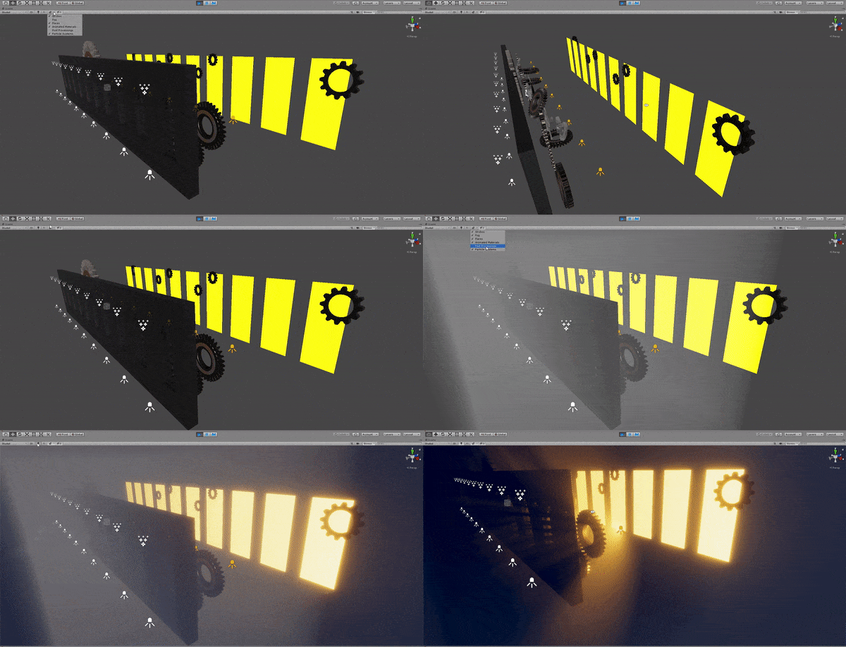
In week 7, we discussed the possibility in class, to play with lighting. Light beams could stream in from several sources in varied directions. We could also play with depth to use light to show and hide the gears.

Using volumetric lighting to pump up visual fidelity from raw to final look

Above, I toggle the volumetrics on, followed by post processing, followed by lights, so you can see the impact they make on the scene visuals.

We used a total of 30 lights for the scene shown above and they are all rendering in real-time. We use 10 walls for this set up, spaced out evenly. Each wall has a rim light, an angled front light, and a top spot light.

To have our spot lights cast visible light beams, we pump up the density of our air particles in the air, using a component known as a Density Volume.

This mimicks fog or haze in a certain region, and the thickness of the air particles can be controlled to our heart’s desire.

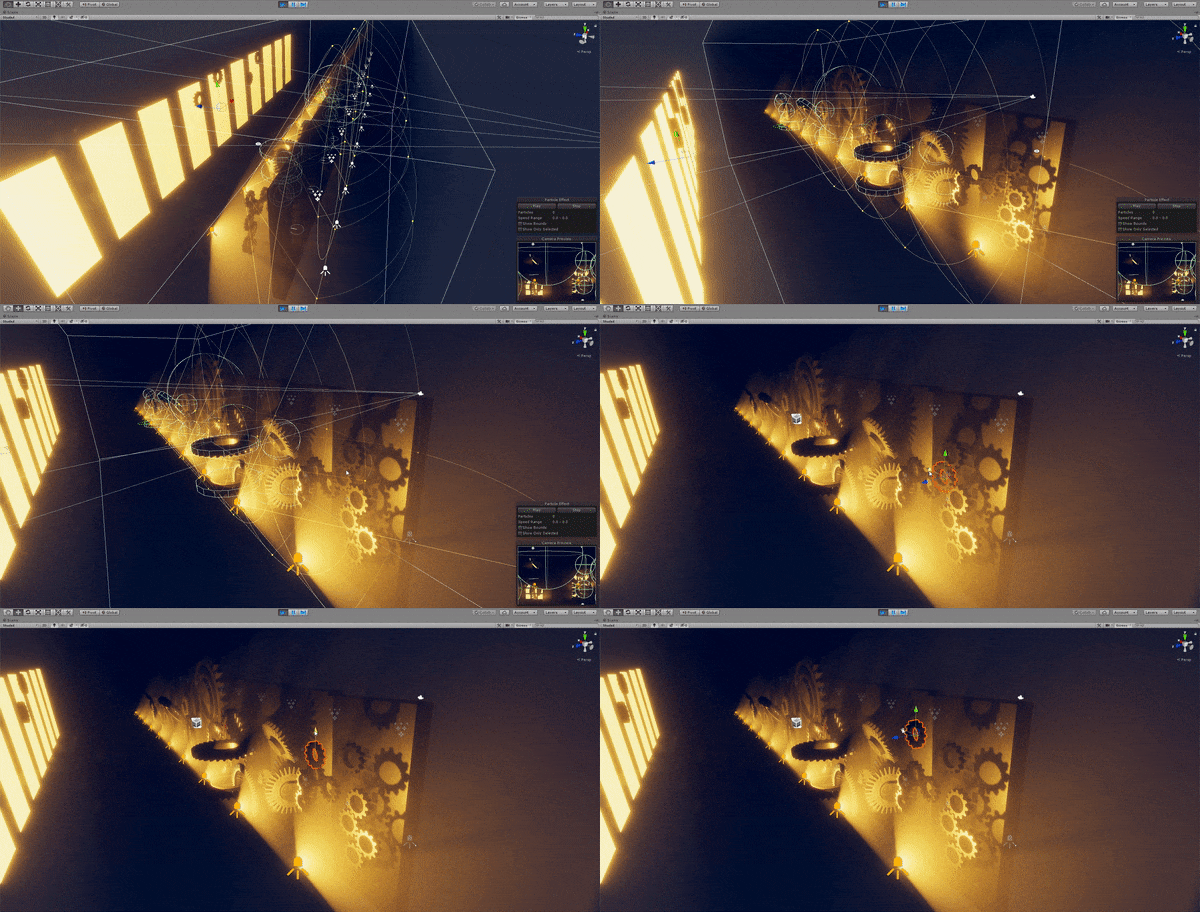
Moving objects freely update shadows and lighting in realtime

The volumetric lighting is interacts dynamically with our objects. We are able to move objects in our 3D scene to arrange the composition as how we like.

This is crucial to our highly iterative process.

All lights are interactive and have option to react with fog
Final Test Result, 3840 x 480, for Media Art Nexus wall test

To get clean lighting and high control over lights, we use shadow-casting meshes that are set to shadows only. These meshes are not rendered to the camera, but act as light ‘blockers’ to stop light from reaching certain areas of the scene. This was essential for perfecting the desired composition during much of the fine-tuning phase.

This method was more effective than light layers. Light layers is a technique to categorize lights and objects into ‘layers’, (like layers in Photoshop), and lights will only affect objects in the same layer as it. While light layers also provide the same functionality, there are too many lights to do that manually on a per-light basis. Shadow casters are slightly more performance heavy, but not significantly, so the faster workflow was preferred.


Fun with VFX

After watching a visual effect shot in Prince of Persia: Sands of time, shared by my groupmate, Ayesha, I was heavily inspired to make my own cool visual effect as well. I decided to start by learning a tool called VFX Graph (within Unity). This is different from the Particle System previously used for sand simulations. I wanted to see if I could make cool things with it.

After watching a tutorial to get me started with this feature, I had managed to create a simple effect, while understanding how the VFX graph works.

Killing two birds with one stone: Learnt a new tool and made myself a screensaver

To create the effect of my name appearing in the title GIF, I first had a model of my name as a 3D text mesh in Maya.

I imported it into Unity as an .fbx file.

Then, I created a basic particle emitter to emit in a rectangle.

Then using a tool, I created a Signed Distance Field (SDF) of my name. I think of an SDF as a texture, but instead of storing colors in each pixel, it stores directions. It is like a wind current. Any air particle that gets caught in the wind will flow along it.

Imagine the above, but in a 3D volumetric representation, so there are 3D arrows in space telling how particles should move. This is how I control seemingly random particles to flow into the direction or into a space I want them to go to.

By assigning the SDF file as input into the VFX emitter, and adjusting how much I want the particles to ‘stick’ to the SDF, I create the effect below.

Forming my nickname with VFX

After writing some code, I exposed the parameters of the VFX graph to be editable in real-time, without having to simulate the entire VFX every time an attribute is changed.

I added interactive sliders at the top right to allow myself or anyone to play with my VFX

For those interested, here is how the Signed Distance Field part of my VFX graph looks like:

A portion how the VFX graph looks like, focused on the SDF node on the right side

The VFX Graph is a node-based system, meaning no programming is required unless you wish to add interactivity. The pros of the VFX Graph is that it is heavily optimized and able to simulate millions of particles in real-time.

Having learnt this earlier on, there could be options that could be explored for this project – for example, using VFX to materialize our compass or the chinese symbols in our earlier video draft.

For reference, I used this SDF baker tool to assist me in generating the Signed Distance Field asset within Unity, without going through an external DCC like Houdini, reducing the need to jump through multiple software.

https://github.com/xraxra/SDFr

References & Inspiration


Sand Simulation VFX Breakdown

This post details the breakdown of how we achieve this result and the tricks discovered along the way to create particle physics simulations:

The frame rate stuttering is a result of the GIF file, not the simulation

Above is a showcase of our custom-made interactive application where I am dragging our sand emitter around the screen with my mouse cursor. Sand is emitted and continue to fall, bouncing off objects. We manage to achieve and render interactive frame rates in almost real-time, rendering and simulating 100,000 individual sand grains colliding dynamically with moving and rotating objects, with physics. Our scene has been highly optimized to render within seconds instead of hours, allowing us to freely edit parameters throughout our iterations.

Warning: This post is quite technical until the end where we share how this was achieved:

When you turn off all the lights and make the sand glow

In making this, the main issues to tackle were:

1) Creating believable sand physics (friction, bounciness, spread)

2) Sand colliding dynamically with other 3D objects that are in motion

3) The sheer quantity of particles on screen simultaneously, and keeping realistic render times

First thoughts & Research

Early talks about whether we should do sand simulation in the group wasn’t very positive.

None of us had done it before, nor are we even aware of what techniques we can use to achieve believable sand.

Sand is a complex substance – it is not a viscous liquid in which we can use fluid simulations. Yet at the same time it does not act as a single mold-able solid like clay.

Research on how to achieve this led to pretty complicated techniques and sometimes involve software beyond our understanding. Even in Maya, we had not gone deep enough to understand how to use Maya’s nParticles, which are our guess at how we would execute it in Maya.

I narrowed my search to see if it was possible to create this in Unity. As it is not primarily a simulation software, there were many challenges and question marks.

Thousands of individual sand grains have to be simulated. And what about collisions? Would our sand interact with our gear geometry in the scene? If it had to be done in two separate software, then compositing them together would also be a challenge – we could do sand overlay on the gears, non-interactively, but we had no idea how that would look. If it is too obvious it’s an overlay of two distinct videos, it won’t look good.

I knew that it was possible to use CPU-based particles in Unity that use an underlying physics engine (PhysX 3.4).

But as much as I wanted to use Unity (as our gears are rendered there), the sheer quantity of particles destroyed any hope of this being possible, or is it?

Many youtube tutorials on how to do real-time sand physics within Unity did not achieve the fantastic results we were hoping for. The sand particles were always too big, and too few.

Sand looks more like large spheres in this video
20,000 particles slowly approached the maximum limit of what was do-able in realtime

The truth is, physics calculations consist of plenty of mathematical operations that are expensive to compute in large quantities.

The best simulations went to 20,000 particles, maybe more. But this was still a far cry from believable sand. In other words, we had little luck with tutorials. Bumping it up would exponentially take a toll on simulation times and make it difficult to iterate creatively.

Achieving interactive frame rates was a challenge. But I wanted to see how far we could push it.

I gave all the important gears a Mesh Collider, and enabled collision on particles so they would be added to the physics engine and collide.

I started with a  basic particle system that simulates 1,000 particles.

1000 Particles

Seeing sand interact with the gears for the first tine is cool. But aside from cool physics, the visuals look nasty. How about 10,000?

10,000 Particles

Better but not good. I pushed for 100,000 particles. This was a huge quantity and the simulation slowed down tremendously.  

100,000 Particles

I decided to be crazy to the extreme, and bump it up by a factor of 10 again!

1,000,000 Particles!

The grain sizes were finally fine enough, but at this point each frame was taking one full second to render. It is not too bad, but still extremely sluggish and difficult to experiment with. It was time to see if we could do some optimization.

We are being frame rate-throttled on the CPU, not the GPU, as the mathematical and physics calculations are done on the CPU. Knowing this, all our optimizations are targeted at the CPU-side.

Optimization Tricks

1) Randomizing per-particle properties creates illusion of more sand

The first secret to get fast simulations is to completely NOT simulate sand particles colliding with each other. Instead, we fake it. To help sell the illusion that the particles collide with each other and pile up, we randomize the per-particle properties, indicated in red arrows below.

Our particle collision module settings

Dampen affects how much velocity a particle loses in contact with a surface (aka friction).

Bounce affects how much a sand particle retains its vertical potential energy. High values make each grain act like a bouncy ball.

We randomize them for every sand grain so a sand grain can be heavy, or light, or bouncy, or slidy. This creates variation in our sand behaviour.

This randomization across the particles create higher coverage of sand across the screen, and results in a “spreading” effect lets us use less particle numbers to give illusion of more sand.

2) Using primitive colliders is simpler for the physics engine to calculate

Secondly, we use basic collider shapes.

How collider shape affects physics calculations

Gears have a very complex shape, but when broken down, it is basically a sphere (circle in 2D). In some cases, using multiple sphere colliders is less taxxing than a single, complicated shape collider.

Sphere colliders are easier to detect collision with, as the physics engine only needs to check the distance between two points in 3D space. This makes spheres the cheapest colliders. As our gears are circles from the camera perspective, we use spheres for our gears’ main body instead of cylinders.

We can use both – objects that require precise collision use mesh, while small objects not prioritized in our composition fall back to primitive colliders, and we can even toggle between the collider types through code in the midst of rendering if we really want full control!

Basic colliders give us up to 5 times faster render times. Now we’re talking speed!

3) Restricting physics to a single plane

Simulation is restricted to 2D space, faster computations

We reduce the particle count needed to be simulated by limiting them to a single plane in our 3D space. This way, it is effectively computed in just 2D while being able to interact with our 3D objects. Withour particles overlapping or hidden in the z-axis, it allows us to be as efficient as possible with the particles we emit.

4) Decrease simulation speed

This last trick can double the render speeds but is case specific. By slowing down our simulation speed to 0.5, we effectively only calculate our physics every 2nd frame instead of every frame. Speed wise, this means the CPU performs half as many calculations over the same period of time. However, this can produce undesired effects, such as slow motion.

There was lots of trial and error involved but bit by bit the simulation got faster and was extremely rewarding to watch.

We went from rendering 1 frame per second, needing 1 million particles, to 10 frames a second, needing only 100,000 particles. That is a 10x speed increase in our simulation and render times!

We went from talking about how many seconds we need to render a frame, to how many frames we can render every second. I was personally amazed that we could simulate 100,000 colliding particles at such speeds.

When it became fast enough to render, we aren’t bogged down by render times, so it was time for the fun stuff!

Out of fun, I made the sand glow by giving it emission, and turned off all our scene lights and made the background black.

This created a very interesting composition:

I then wrote the code to make a button that can toggle between both modes in real-time through a single click, as can be seen by the “FX Mode” white button at the top right of the above GIF. This makes it convenient to test compositions while we experiment.

I doubt anyone is interested in the code I wrote (C#), but for the curious:

Function that is executed when FX mode is changed

Additionally, I added a slider that progressively trades off performance for quality for our final render, so we can choose how much sand we want and the quality of the simulation results, based on how much time we are willing to wait for it to render. The longer we are willing to wait for longer render times, the higher the sand particle count. Collision parameters are not changed as this keeps the render consistent regardless of the quality used.

Progressively increasing quality increases sand particle count and render times, while inversely decreasing sand grains’ size

This is done by writing a script to set our particle sizes and emission count. Again, for anyone who is interested to look at the script to achieve this:

I also wrote another script that reduces the particles used during edit mode, and pumps up the particle count only during our rendering. This way we can iterate even faster with less lag in the scene view during our iterations, and not have to manually remember to increase the final quality before we render.


Gears 3D Modelling Breakdown

This is part 1, the beginning of the entire development process focusing on Concept 2 of our ideation for the Silk Road theme. For subsequent parts, please see:

Part 2 (Sand simulations)

Part 3 (VFX)

Part 4 (Lighting)

One of the core visual inspiration of this project is gears. Thus, we started with asset creation for these elements.

GIF showing current stage of render

Below is a high resolution video result of our current 3D gears render, 20 seconds rendered at 3840 x 2160px:

https://vimeo.com/user85218205/review/360882605/0bd928edf5

This post details the breakdown in the asset creation pipeline and how rendering of our gears is achieved. This breakdown showcases the entire pipeline:

  1. Modelling
  2. Texturing
  3. Rendering
  4. Lighting
  5. Post Processing
  6. Animation
  7. Particle Effects

The composition is not confirmed. Should the video not work, this is a high resolution screenshot from the video render.

Modelling the Geometry

Modelling is our first phase to obtain the 3D geometry we need. Modelling each 3D gear asset individually can be a labourous process. But what if it did not have to be this way?

Using Maya 2018, we discovered that it is possible to procedurally generate gears instead of hand-modelling individual ones, leading to huge time savings and procedural generation meant our assets are non-destructive (able to go back to edit easily its parameters).

Using procedurally generated attributes to modify our gear

Here is a screenshot presenting attributes of the gears we can edit when creating our gears through this method. It allows for easy experimentation.

Parameters to allow flexible creation of gear polygons

With varying parameters, the aim was to produce interesting and contrasting shapes and proportions.

Various types of gears created in Maya 2018

To give a realistic look, bevels were added to prevent the ‘CGI look’ resulting from edges with 90 degree angles. This will allow gears to catch lighting and reflections more realistically when lighting is added later on.

Without bevels (left) vs With bevels (right, highlighted in orange)

To make sure our gears look old enough to be from the 19th Century, much detail has to be considered in its texturing. It is easy to make metal look shiny and glossy. But this clean and shiny look is not what we want. Thus, we move to the next phase.

Adding detail through textures

With our models done, we need to make them look convincing by applying 2D textures and set up our material to emulate real-life materials, such as their physical properties (glossiness, smoothness).

For textures, I looked at various metals:

  • Galvanized Metal
  • Scratched Steel

To give the old, worn-down look, I use:

  • Grunge
  • Rust
  • Surface imperfections
Grunge Albedo Texture, that was later used as a detail mask

To achieve a realistic finish, a technique called physically-based rendering is used. The standard surface shader in Unity supports this. The nature behind this idea is that in real life, no surface is perfectly flat and they have to respond to dynamic lighting easily in our CGI pipeline.

Normal maps lets us add micro-surface detail by simulating scratches, a common surface imperfection in metals. Notice that we also vary reflection in certain areas – a metal surface is not equally reflective across its surface.

Rust was applied using a Detail Mask, specifying three channels (Albedo, Smoothness and Normal).

In Photoshop, I took a rust texture and using a soft brush, desaturated areas of the texture where I did not want rust, as well as the rust layer itself, until I was happy with the percentage coverage of the rust on the gears.

Testing of rust amount on material

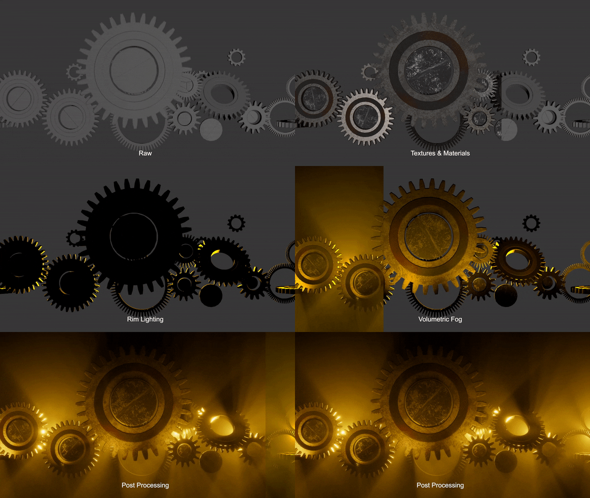
Below is a summary of the gear at different stages of the material set-up process for comparison of start to end.

Gear Texturing and materials step by step breakdown

Notice how in step #2 the reflections and captured lighting falling on the gear are a lot more believable.

The detail masks added in steps #3 and #4 also affect the surface reflection, in addition to the albedo (color), as seen in the specular areas.

These are our two material set ups.

With our meshes and textures, we proceeded to try rendering them to see how they look.

Rendering

In addition to quality results, the key to our workflow is as much about being able to iterate quickly throughout our conceptualization process.

Using the power of Real-time Rendering

I did not use Maya or Cinema4D to texture or render the gears in the meantime, as I wanted to adopt a faster rendering solution, observing that the long render times in these softwares limit what we can change in the final weeks, and it can be creatively-limited. Thus, I tapped onto the power of a game engine to do real-time rendering, and also because I am accustomed to using it.

Note: Above is a screenshot, not a video, as it is too large to upload here

We could get a 4K video rendered in 20 seconds in the Unity game engine, complete with lighting, reflections, shadows, particle effects, post processing and color grading. What is amazing is that it outputs a video directly with the option of individual image frames for lossless quality. So we can get a final render look and iterate extremely quickly without going through external video editing software, minimizing additional rendering steps. This lets us focus on the creative aspect instead of worrying about rendering time as it takes seconds to render high resolution 3D content instead of hours.

Visualization in Unity editor. Top shows our scene viewport, bottom shows the immediate render output.

This additional creativity time let us experiment a lot with different lighting, camera perspectives and screen compositions as seen in pictures below. Plenty of happy accidents came from the results of this which will be talked about in future posts, which will be exciting to share. These would not have been possible in a pre-rendered solution. We are still open to use cinema4d if needed later on in the project.

Exploring compositions and perspectives on the first night of testing:

Lighting & Post Processing

Lighting

The scene itself uses fully real-time and dynamic lights. These lights can be changed on the fly interactively to achieve results we want.

The scene is made up of a directional light as the key light, and a few spot and point lights for fill and rim lighting, as well as strategically placed lights to show off the surface detail of our gears.

Having fun with lighting adjustments (at the top I am adjusting the light, bottom is output render)

Using lighting, it is easy to change the mood and tone of the scene globally as well. Above is one of the first few early videos of me playing with the directional lighting.

Post Processing

Post Processing involves several effects, one of which is tonemapping to get a filmic look. We also slightly bump the contrast and apply subtle color grading where needed.

Other subtle effects include ambient occlusion, which darken edges where objects appear to touch, making them look more grounded in reality, as well as bloom to simulate how intense light appear as bright spots through a camera lens.

Depth of field was also used to blur out gears in the background, just to test the composition and bring focus to the main gears.

These effects are added in the 3D engine so we can preview the gears’ look without going it through AE or other compositing softwares for faster iteration.

Reflections

Reflection Probe lights up darker areas of gears

Ambient lighting is also used to set-up optimized reflections, by using something called Reflection Probes, as seen above. The reflections light up the darker areas of the gear parts, revealing details that are previously in shadow. A Reflection Probe is an optimized way to capture a 360 cubemap to cast as reflection onto nearby objects. The effect can be toggled off if we prefer the areas in shadow to remain dark.

This technique is cheap and fast to compute, and is highly optimized compared to Maya and C4D which calculate reflections by simulating light rays, known as ray tracing, which is comparatively fairly expensive computation. Our current technique of using reflection probes works well as we do not need super accurate mirror-like sharp reflections.

Animation

This project does not feature animation heavily, but is still essential to the process. To create intricacy and mesmerizing effects, we will play with:

  1. Speed of rotation of gears
  2. Direction of gear rotations
  3. Animating of lights (future post)
  4. Layering of multiple rotating gears in z-axis space

The gears are not animated in Maya using keyframes as we want to be able to change individual gears’ rotation speeds easily and flexibly. Thus, the gears are rotated using a script.

I wrote a script that lets me specify values (in degrees per second) to rotate the gear on a chosen axis, by modifying its transform values.

The script can easily be copied and applied to every gear, with each one rotating at selected user-input speeds that can be changed on the go. Below is a screenshot of the script written in Visual Studio (C#), with comments, for those interested.

RotateScript.cs

To give illusion that gears are interlocked and rotation in sync with one another, we discovered this engineering trick:

Speed of Rotation is inversely proportional to its radius and number of teeth (sides).

Which means to say, if we halve the size (radius) of a gear, we have to halve the number of teeth and double its rotation speed.

Being a programmer helped discover this as I often use power of two values and this made me realise that as long as we ensure that our gears are modelled with exactly Power of Two number of sides – 8, 16, 32, 64, they are easily compatibility with one another.

Particle Systems

Lastly, a test 3D particle system emits chinese symbols at the bottom right, which are tests for linking to the symbols on a compass we have yet to model.

Particle Effects test

The particles’ direction, positions and speeds are also yet to be confirmed. The initial plan is to have them float upward from the surface of the compass, which is different from what our current footage shows.

The particle system uses an emissive shader with a chinese symbol as texture, with its velocity generated by perlin noise to create a randomized movement.

Tutorials & References

Lastly, here are some additional materials referenced that aided in the  process.

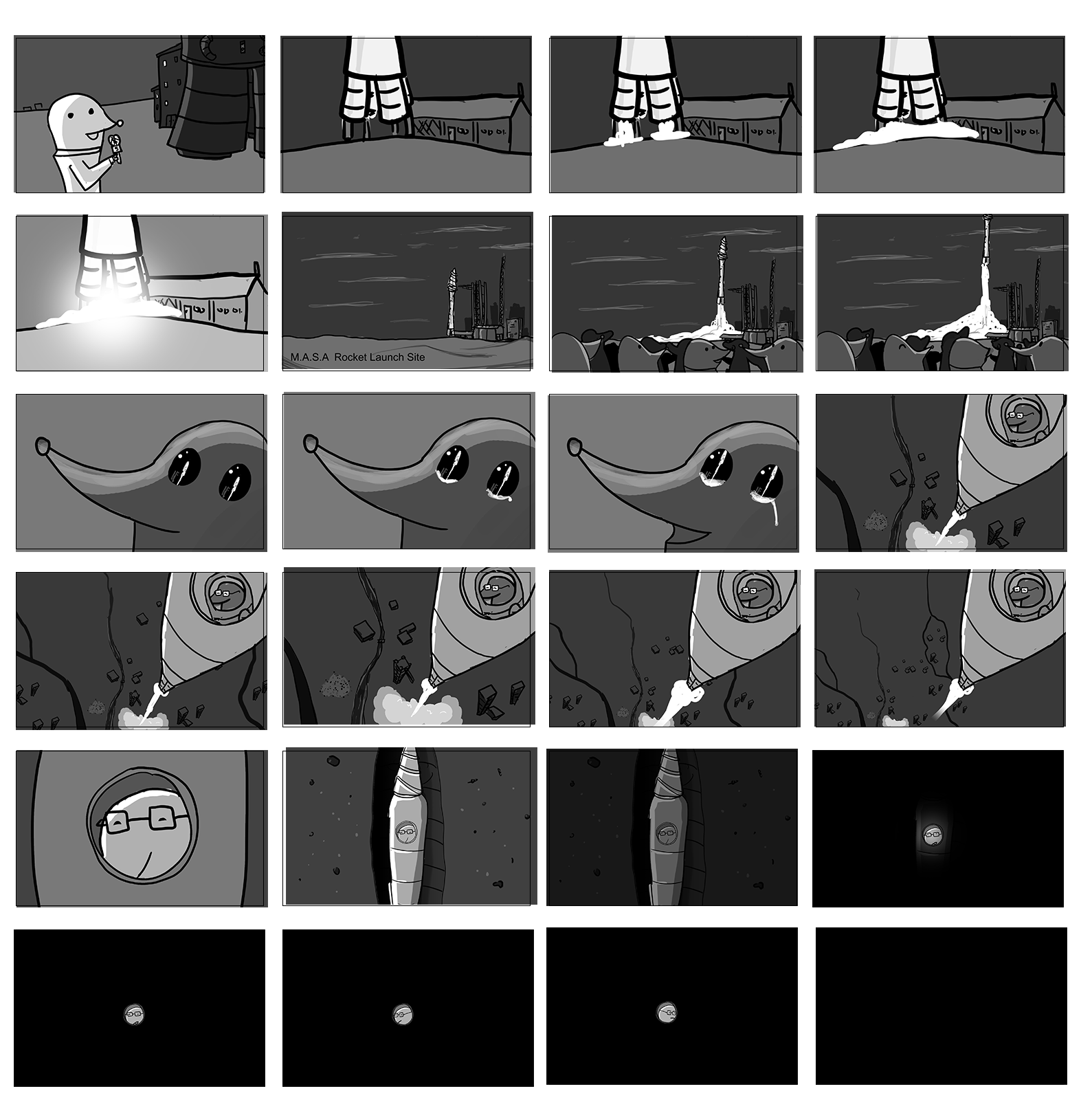
One Giant Leap for Molekind Rocket Sequence – Storyboard

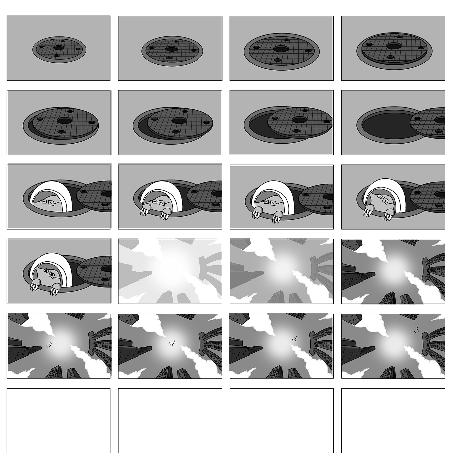
Below are the raw frames that made up the storyboard as well as some GIFs that illustrate the pacing of the frames leading up to the final animatic.

Final Animatic

Click here to see the final animatic and the master post

Storyboards

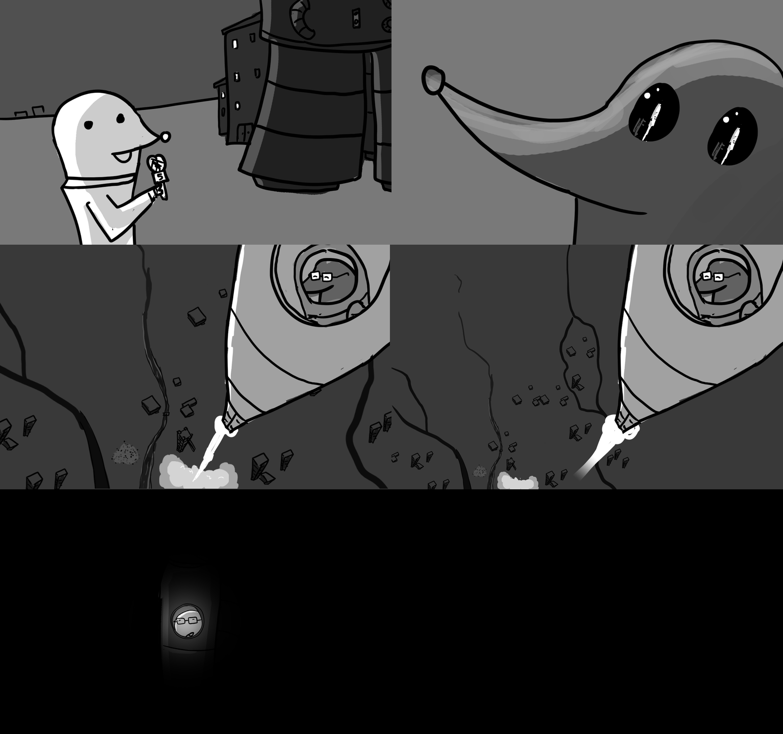
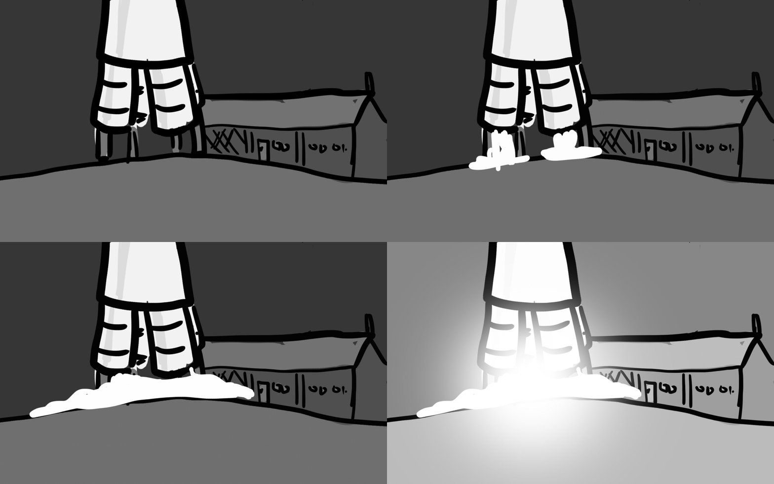
“Rocket Launch Sequence”

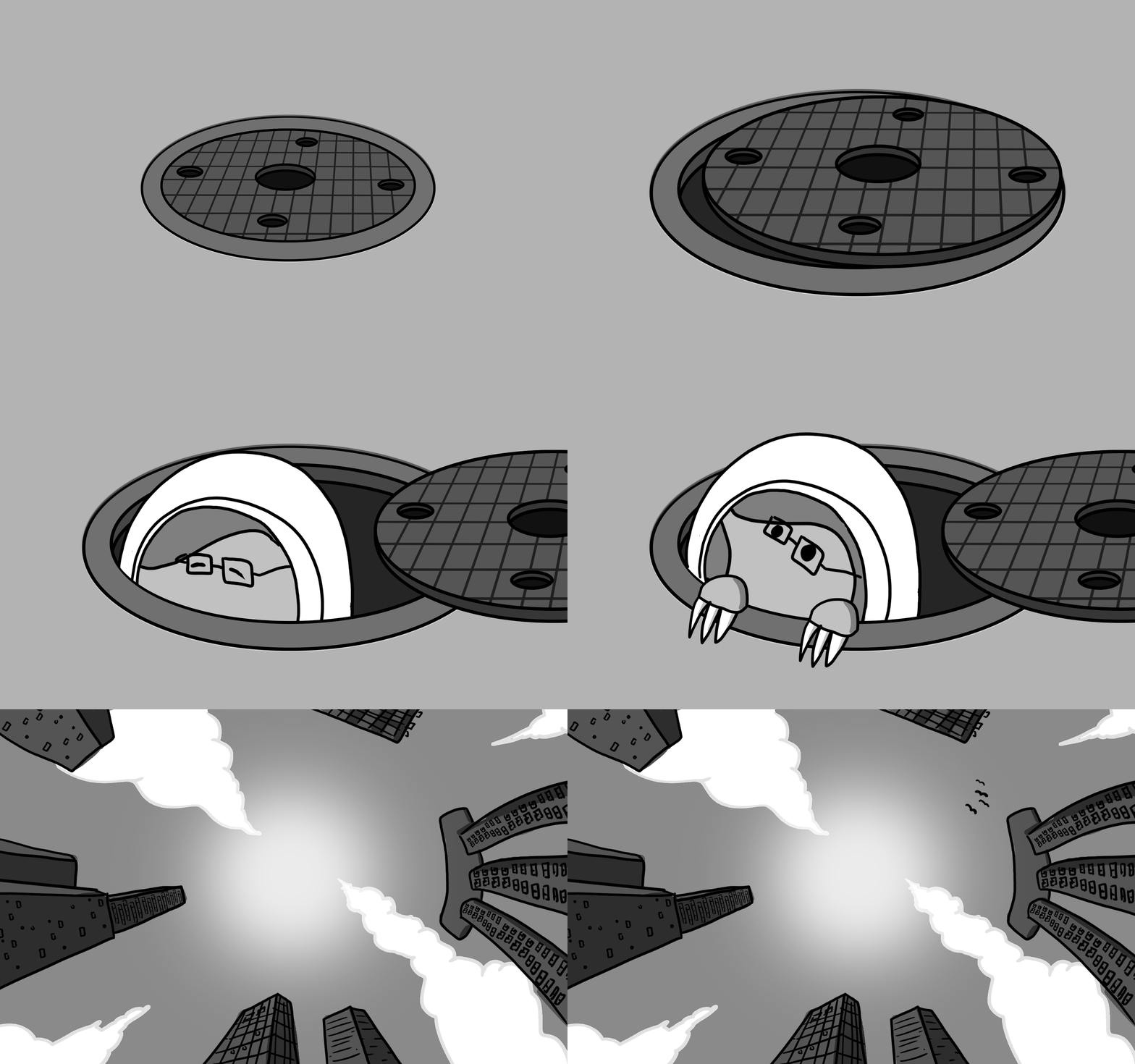
“Emerging from Manhole Sequence”

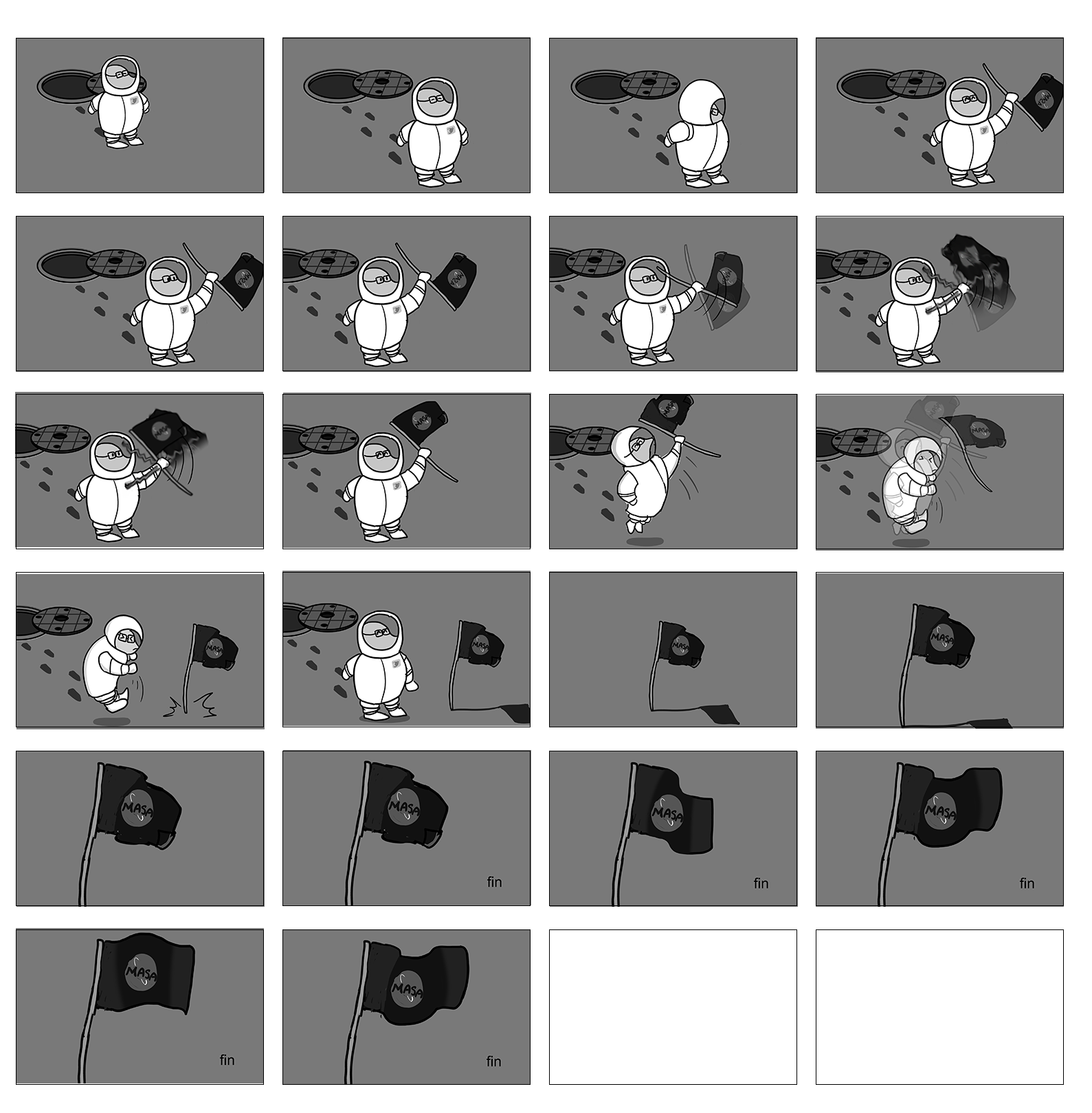
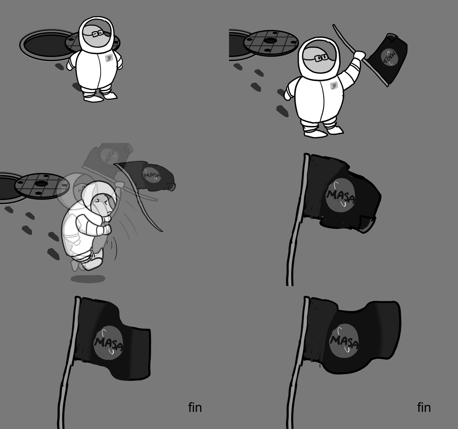
“Moon Landing Flag Sequence”

Early mock of various sequences in the animatic adjusted for pacing: