One-liner concept
Tele-bonsai is a tele-operation machine that will allow a bonsai master to remotely help you tailor-cut your beloved bonsai from anywhere in the world.
CAD time !
Yes, it is very comforting to design and construct everything on the computer. Laser-cutting was the tool of choice and I had plenty of throwaway 2mm acrylic boards, so I worked my design around that. Though it wasn’t as convenient as being able to 3d print ‘any’ shape, I find that it was a good practice for designing modular small parts that can fit together to make a larger shape. And my recent foray into cardboard design helped somewhere too. CAD also allowed me to play with different ideas without spending any time and money before committing, unlike relationships in real life :p
Parts assembly
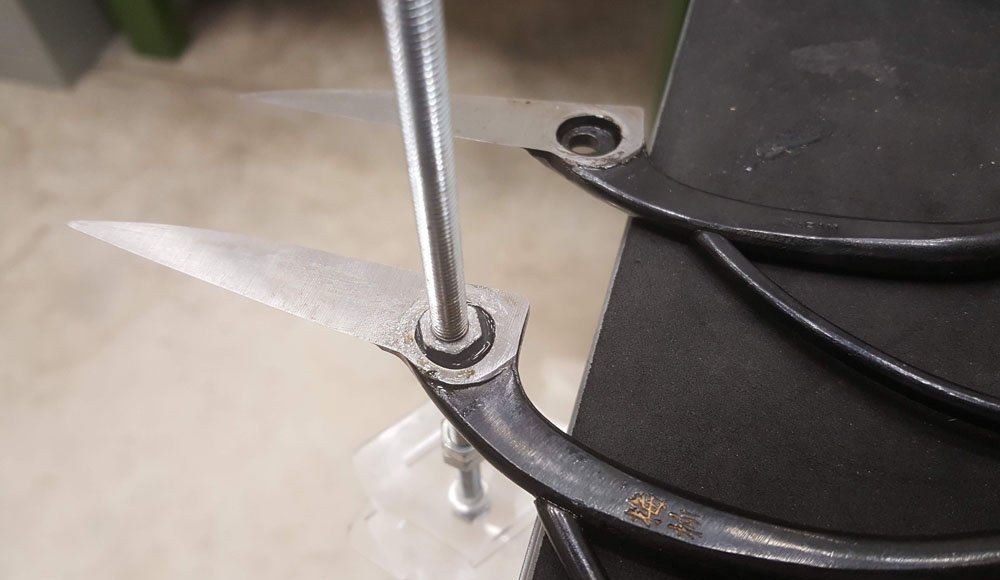
epoxy nut into shears for clamping, and yes it’s a real japan made bonsai shears ($18 a pop) !
Locking the (bonsai) shears to the shaft is particularly challenging, I tried a variety of methods, but finally stuck to using epoxy and sticking a nut inside a hole inside the shear.

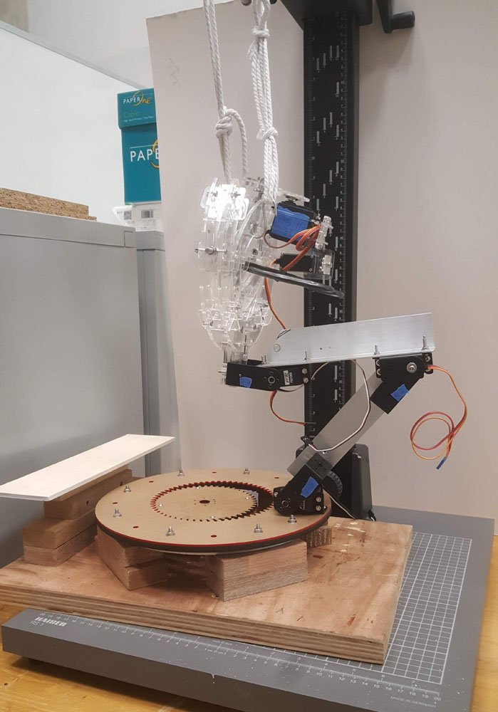
lazy susan as base

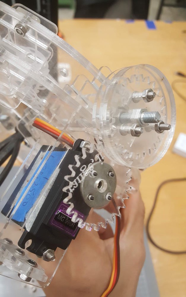
lazy susan with internal gears
Next up was the lazy susan for the rotating base. This went pretty smoothly; I chose an internal gear of about 6-ish:8 ratio to reduce the amount of degrees lost as I am using a servo and would like to rotate at least 120 degrees. Originally planned for 2 pieces of 3+mm material, but ended up using 5 pieces for the robotic side’s base.
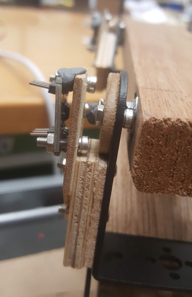
Encoder with magnet assembly
I have chosen to use magnetic encoders(AS5600) for this project as they weigh practically close to nothing and have ‘infinite’ resolution, but it turns out to be quite a bit finicky then expected and proved to be quite a problem as the premise of tele-operation relies on accurate sensing. Hardware encoders should have been used, though at the expense of weight and footprint, but would most likely be much more reliable. I am not absolutely sure but it seems the noise ripple from the power supply for the servos messes the signal significantly, though the effect is less pronounced in the wee hours(12am – 1.30am). But still its very accurate for what it costs and its size. The ‘spacers’ are for fine-tuning the spacing between the diametric magnet and the encoder.
gear assembly for shears frame
The gear assembly is quite hard to lock onto the rotating shaft, and it seemed to slide abit, though the frame didn’t quite make it to the final; more on that later.
Test assembly
.
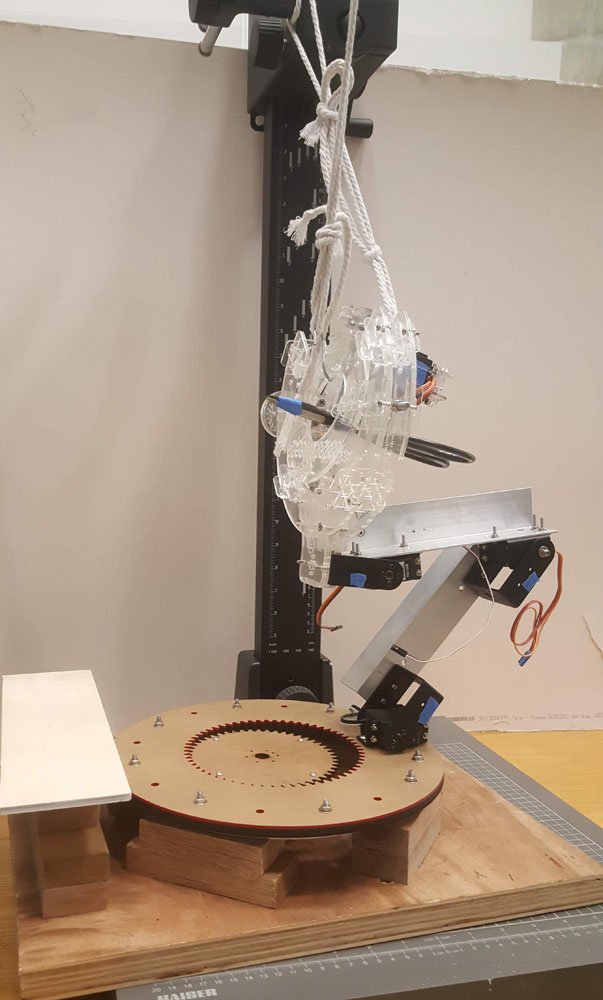
testing with safety lines
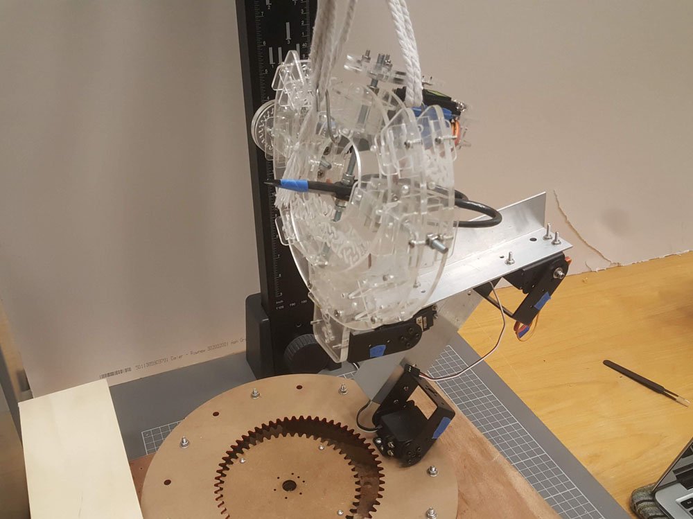
testing with safety lines
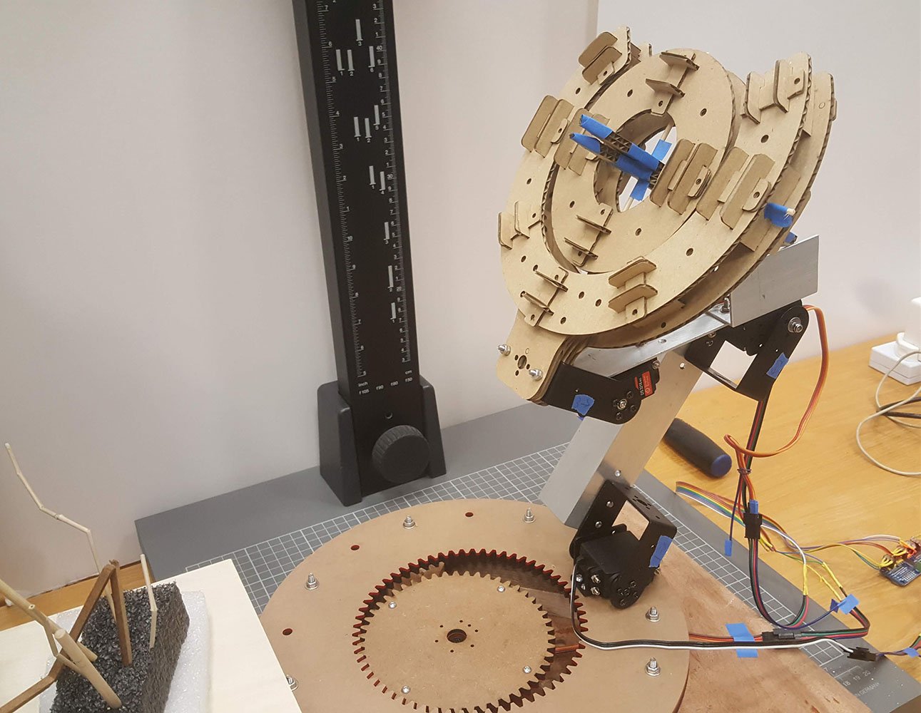
Moment of truth!
First off, I was quite pleasantly surprised to be able to assemble everything without too much drama; CAD designs sometimes fall into the pitfall of being impossible to assemble.
However, I must admit, my heart sank as I came to the conclusion that the motors won’t be able to support the frame, but lesson learnt. The three joints in particular are not favorable; the middle one had to support a great deal of weight and I burnt up a beefy 20kg/cm rated servo for that…
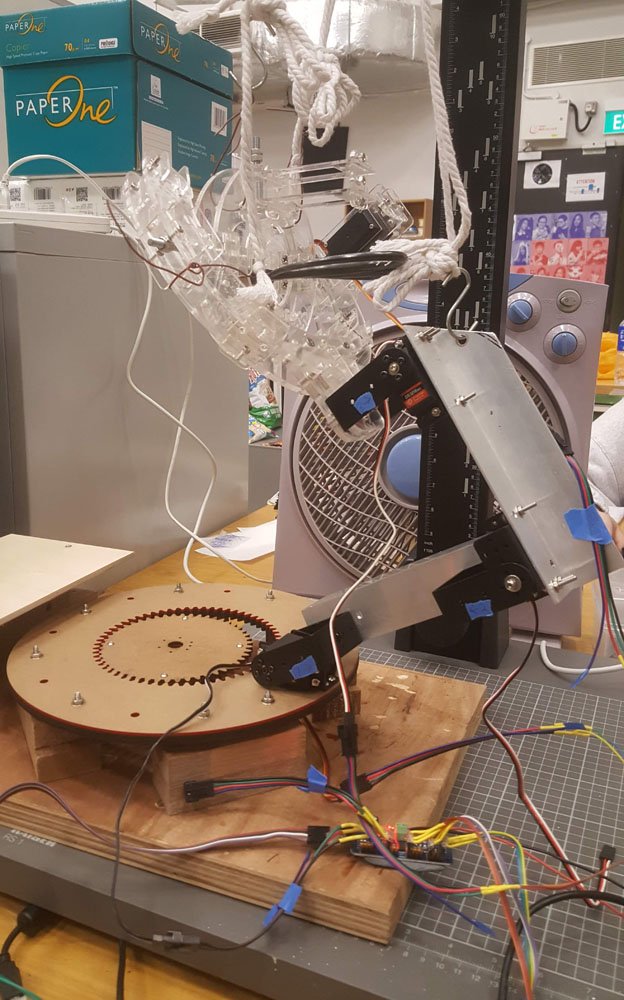
testing with safety lines
I tried to shortening the distance between the servos in hopes of them having more torque to overcome the heavy frame, but to no avail. Oh well..
final controller setup
Wiring & electronics
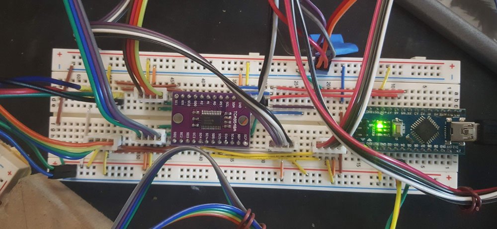
final wiring

controls for debug
It was a good time to practise tidy wiring, and I did just that. It’s oddly satisfying to spend(waste) the time to wire nicely. But it does help; I only had to troubleshoot 2 wrongly placed wires for a whole day of wiring. And lots of custom wiring splicing as well. It was a welcome break from the construction work.
I used a hardware encoder to determine all the limits for each of the servos to prevent mishap before powering up anything. The magnetic encoders took quite a while to figure out its quirks, and I should probably have done much more extensive testing before committing to this approach.
The coding was pretty straightforward, the i2c did throw me off a bit for a couple of hours; initially I couldn’t figure out why the 16 channel PWM controller wasn’t detected when I combined the circuit with the magnetic encoders(using a tca9548a i2c multiplexer), and realised I had to connect it to one of the channels on the multiplexer instead of running it in parallel. It was a rather silly mistake on hindsight. But it is certainly easier than having 2 Arduinos sending data back and forth.
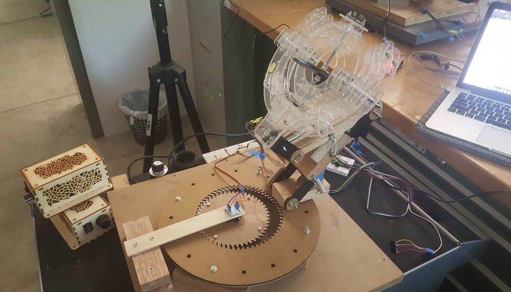
Final assembly
After much deliberation, I decided to laser-cut a cardboard replica of the frame for the robot side, just for visualisation sake.
Yes, cardboard .. better than nothing though …
Final demo
Not available yet, trying to pick a good timing(less people on campus = less noise in the power lines?) to shoot a video, or figure out how to use a battery pack to power the servos … stay tuned … ?
You must be logged in to post a comment.