
U-turn: From moving furnitures to moving your body !
Weaving

small prototype for weaving
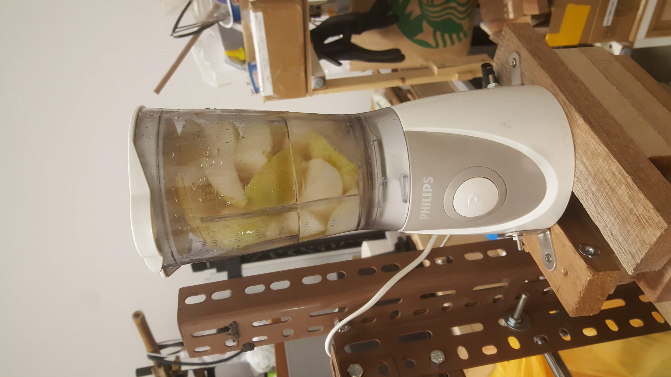
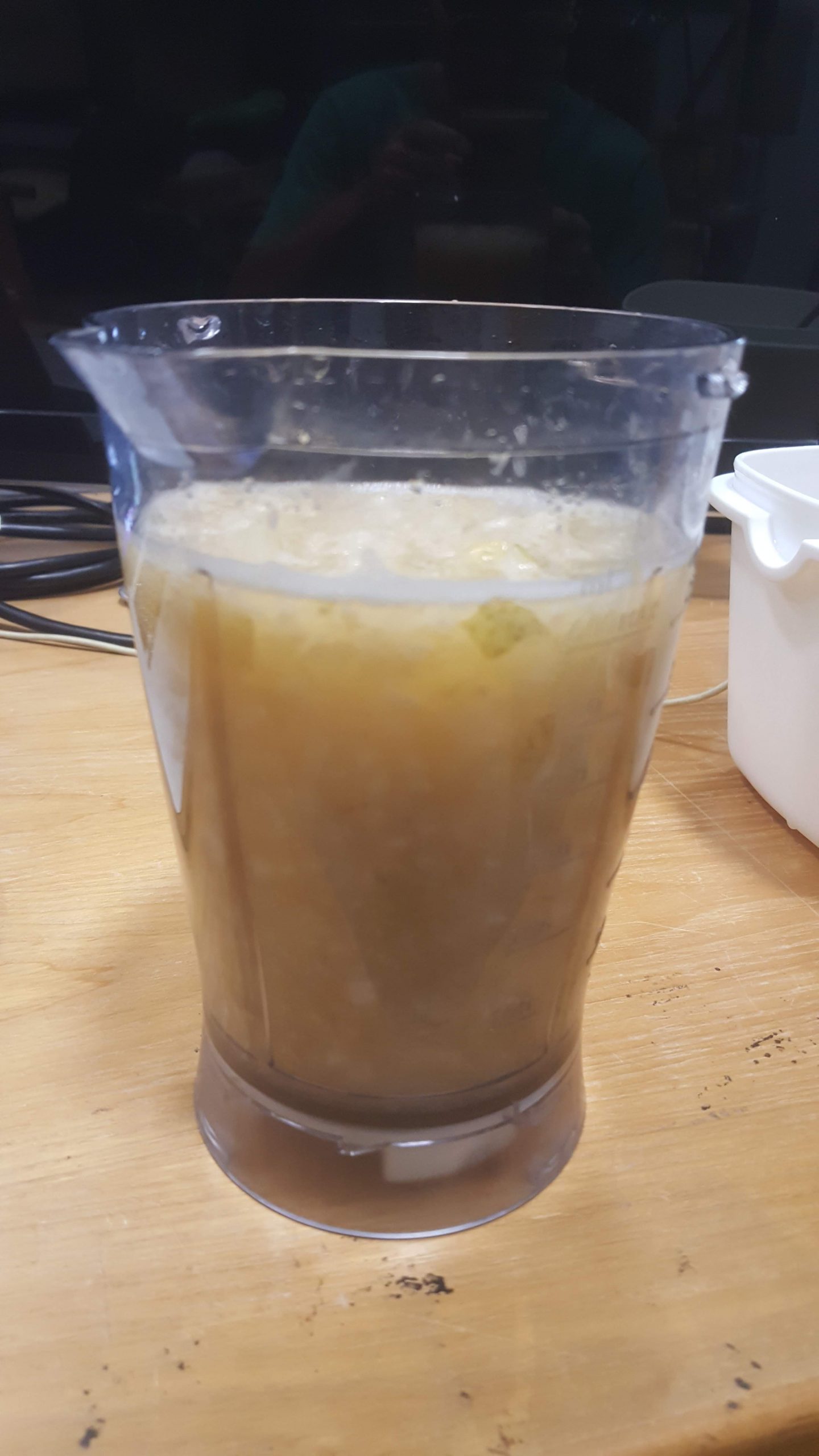
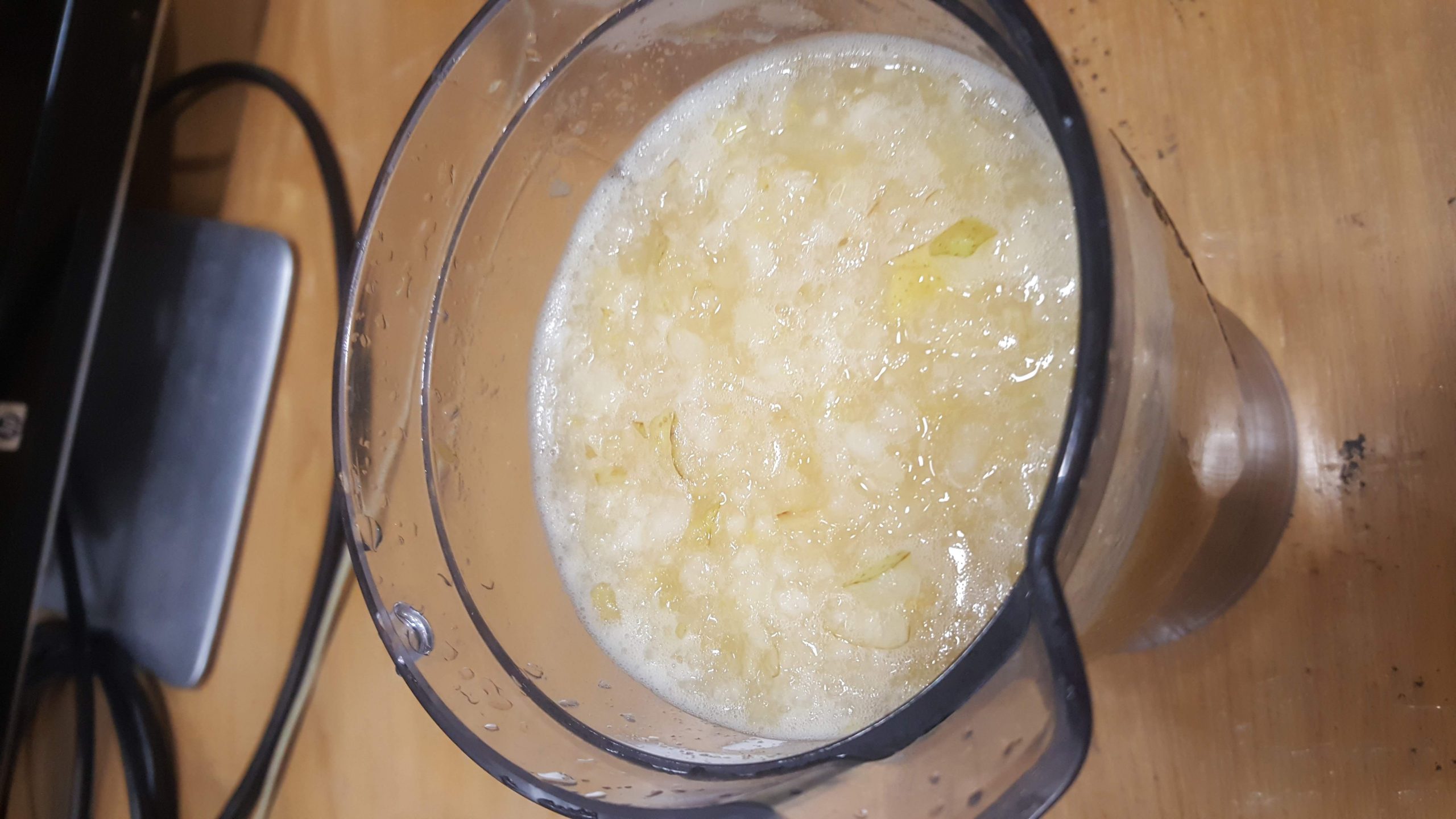
Blender
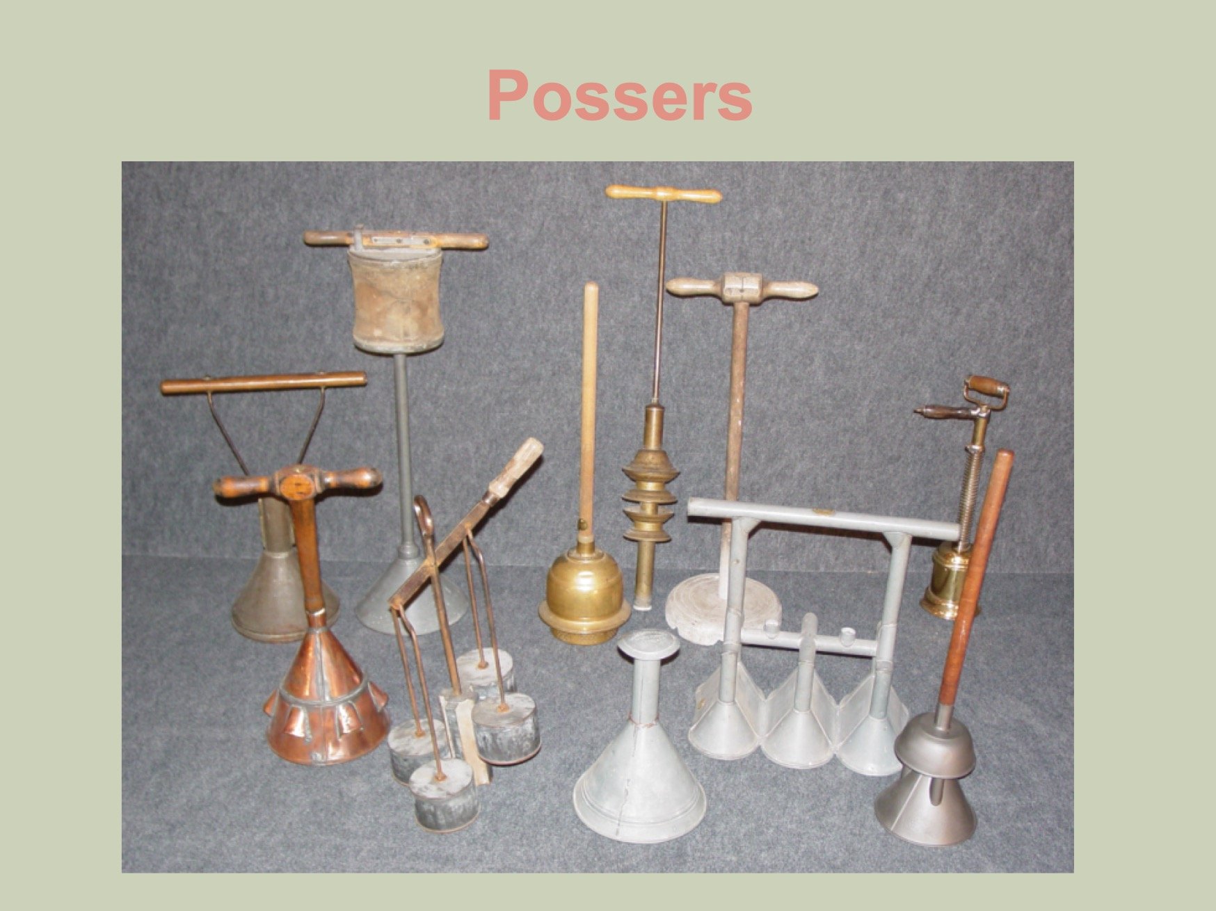
Washing machine
https://www.oldewash.com/

https://www.oldewash.com/
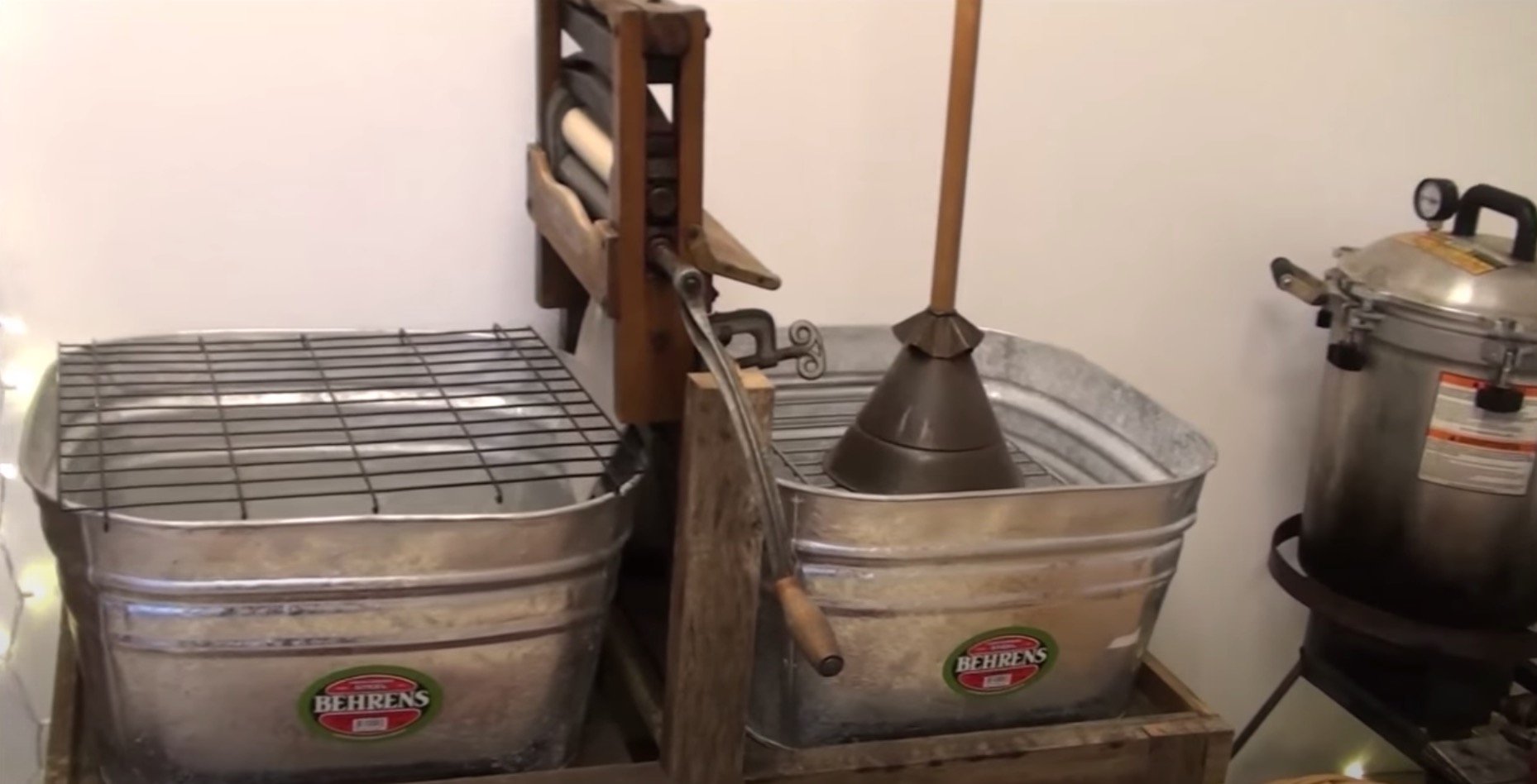
https://www.youtube.com/watch?v=AHOeoiJU6xE
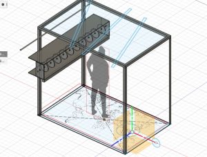
Space layout

There are 8 posts tagged m (this is page 1 of 1).
small prototype for weaving
https://www.oldewash.com/
https://www.oldewash.com/
https://www.youtube.com/watch?v=AHOeoiJU6xE
Building Robots during the semester …
Working with servos to create simple moving things…
Exploring simple expression and movement
A Braitenberg vehicle is an agent that can autonomously move around based on its sensor inputs. Depending on how sensors and wheels are connected, the vehicle exhibits different behaviors.
from Interactive Devices ….
Working on more electronics and mechanics.
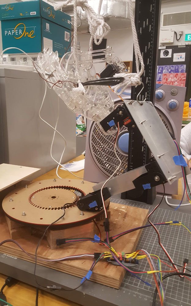
Tele-bonsai is a tele-operation machine that will allow a bonsai master to remotely help you tailor-cut your beloved bonsai from anywhere in the world.
Yes, it is very comforting to design and construct everything on the computer. Laser-cutting was the tool of choice and I had plenty of throwaway 2mm acrylic boards, so I worked my design around that. Though it wasn’t as convenient as being able to 3d print ‘any’ shape, I find that it was a good practice for designing modular small parts that can fit together to make a larger shape. And my recent foray into cardboard design helped somewhere too. CAD also allowed me to play with different ideas without spending any time and money before committing, unlike relationships in real life :p
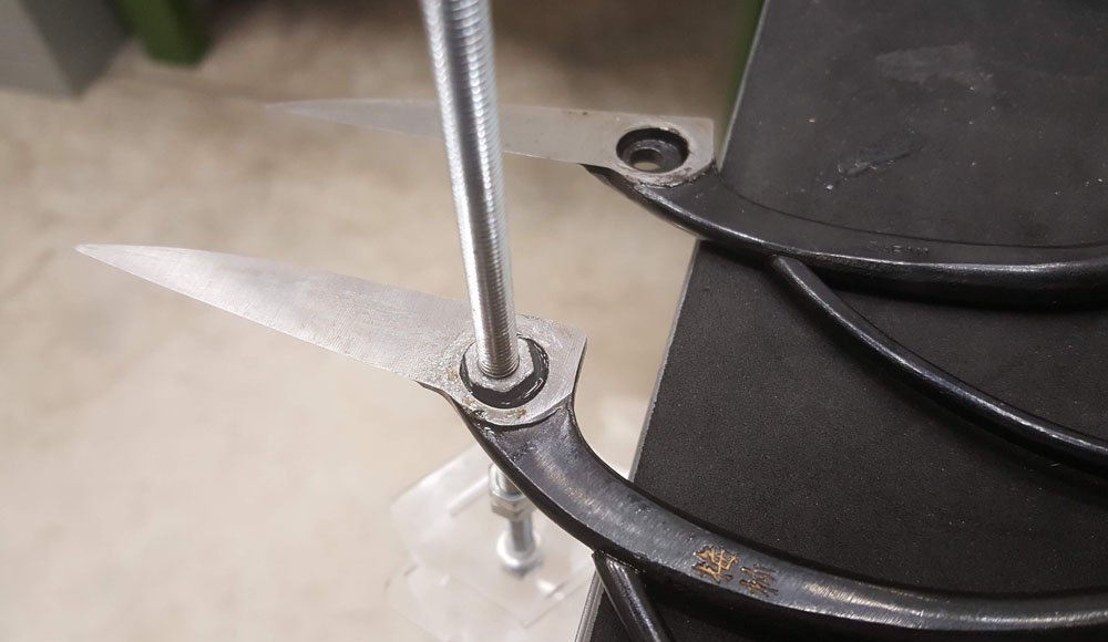
epoxy nut into shears for clamping, and yes it’s a real japan made bonsai shears ($18 a pop) !
Locking the (bonsai) shears to the shaft is particularly challenging, I tried a variety of methods, but finally stuck to using epoxy and sticking a nut inside a hole inside the shear.

lazy susan as base

lazy susan with internal gears
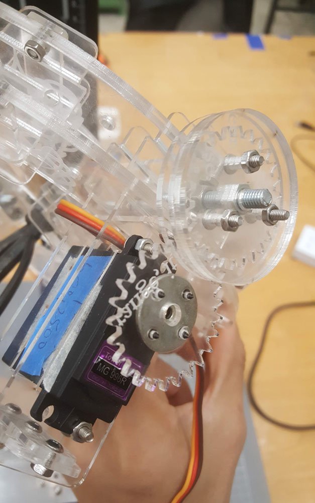
Next up was the lazy susan for the rotating base. This went pretty smoothly; I chose an internal gear of about 6-ish:8 ratio to reduce the amount of degrees lost as I am using a servo and would like to rotate at least 120 degrees. Originally planned for 2 pieces of 3+mm material, but ended up using 5 pieces for the robotic side’s base.
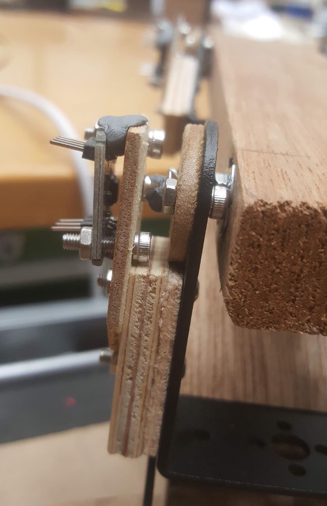
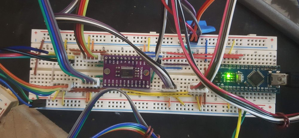
Encoder with magnet assembly
I have chosen to use magnetic encoders(AS5600) for this project as they weigh practically close to nothing and have ‘infinite’ resolution, but it turns out to be quite a bit finicky then expected and proved to be quite a problem as the premise of tele-operation relies on accurate sensing. Hardware encoders should have been used, though at the expense of weight and footprint, but would most likely be much more reliable. I am not absolutely sure but it seems the noise ripple from the power supply for the servos messes the signal significantly, though the effect is less pronounced in the wee hours(12am – 1.30am). But still its very accurate for what it costs and its size. The ‘spacers’ are for fine-tuning the spacing between the diametric magnet and the encoder.
gear assembly for shears frame
The gear assembly is quite hard to lock onto the rotating shaft, and it seemed to slide abit, though the frame didn’t quite make it to the final; more on that later.
.
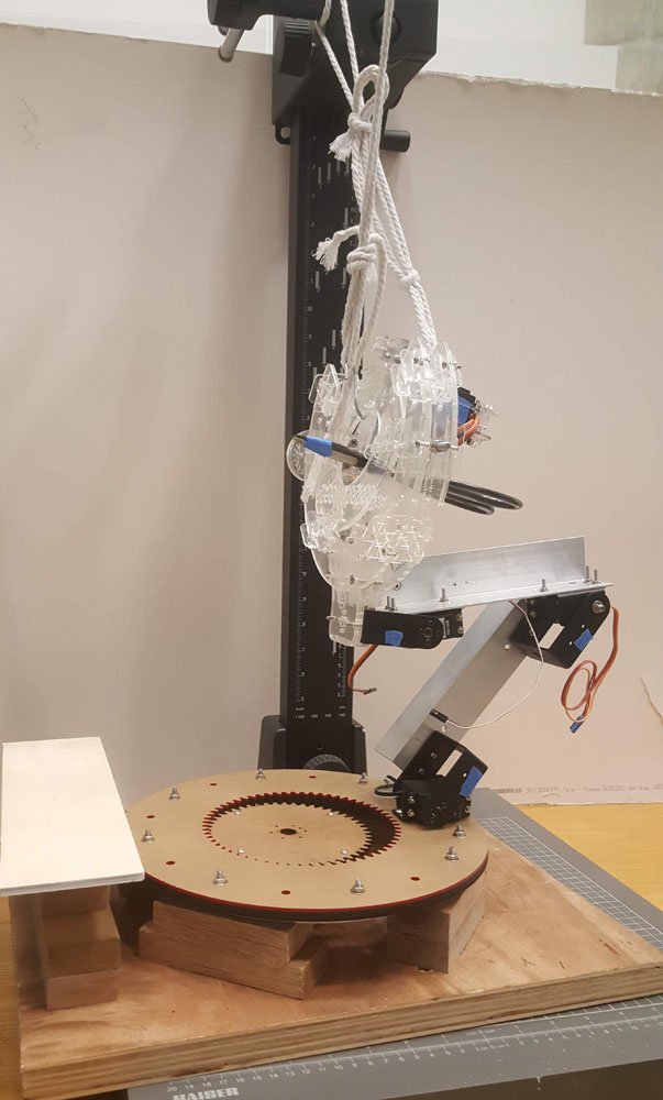
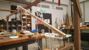
testing with safety lines
testing with safety lines
Moment of truth!
First off, I was quite pleasantly surprised to be able to assemble everything without too much drama; CAD designs sometimes fall into the pitfall of being impossible to assemble.
However, I must admit, my heart sank as I came to the conclusion that the motors won’t be able to support the frame, but lesson learnt. The three joints in particular are not favorable; the middle one had to support a great deal of weight and I burnt up a beefy 20kg/cm rated servo for that…
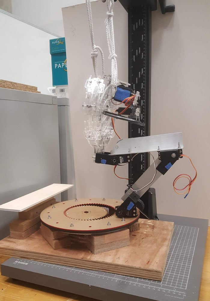
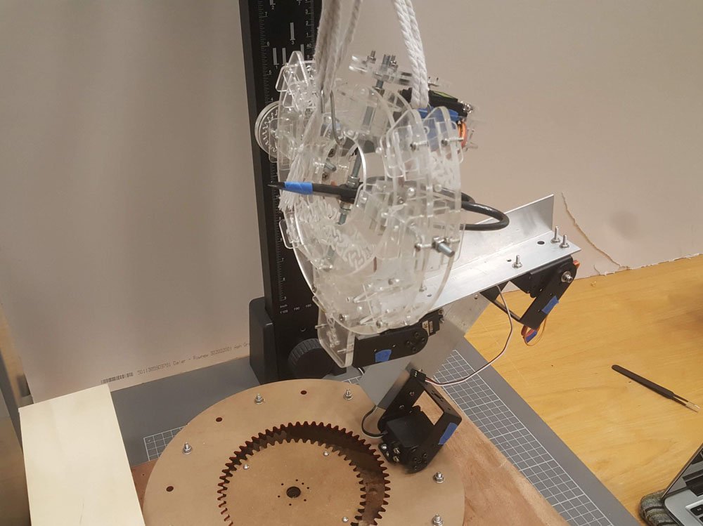
testing with safety lines
I tried to shortening the distance between the servos in hopes of them having more torque to overcome the heavy frame, but to no avail. Oh well..
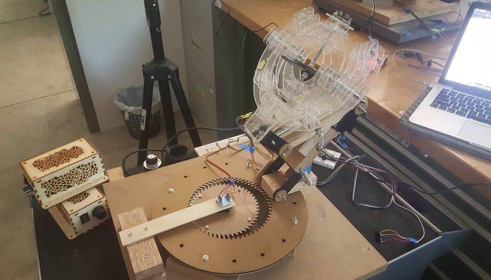
final controller setup
final wiring

controls for debug
It was a good time to practise tidy wiring, and I did just that. It’s oddly satisfying to spend(waste) the time to wire nicely. But it does help; I only had to troubleshoot 2 wrongly placed wires for a whole day of wiring. And lots of custom wiring splicing as well. It was a welcome break from the construction work.
I used a hardware encoder to determine all the limits for each of the servos to prevent mishap before powering up anything. The magnetic encoders took quite a while to figure out its quirks, and I should probably have done much more extensive testing before committing to this approach.
The coding was pretty straightforward, the i2c did throw me off a bit for a couple of hours; initially I couldn’t figure out why the 16 channel PWM controller wasn’t detected when I combined the circuit with the magnetic encoders(using a tca9548a i2c multiplexer), and realised I had to connect it to one of the channels on the multiplexer instead of running it in parallel. It was a rather silly mistake on hindsight. But it is certainly easier than having 2 Arduinos sending data back and forth.
After much deliberation, I decided to laser-cut a cardboard replica of the frame for the robot side, just for visualisation sake.
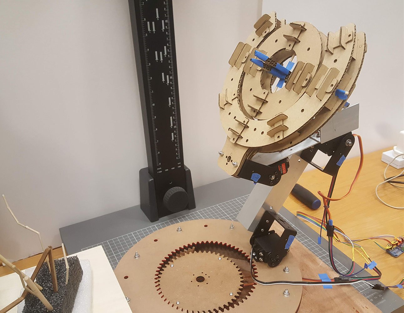
Yes, cardboard .. better than nothing though …
Not available yet, trying to pick a good timing(less people on campus = less noise in the power lines?) to shoot a video, or figure out how to use a battery pack to power the servos … stay tuned … ?
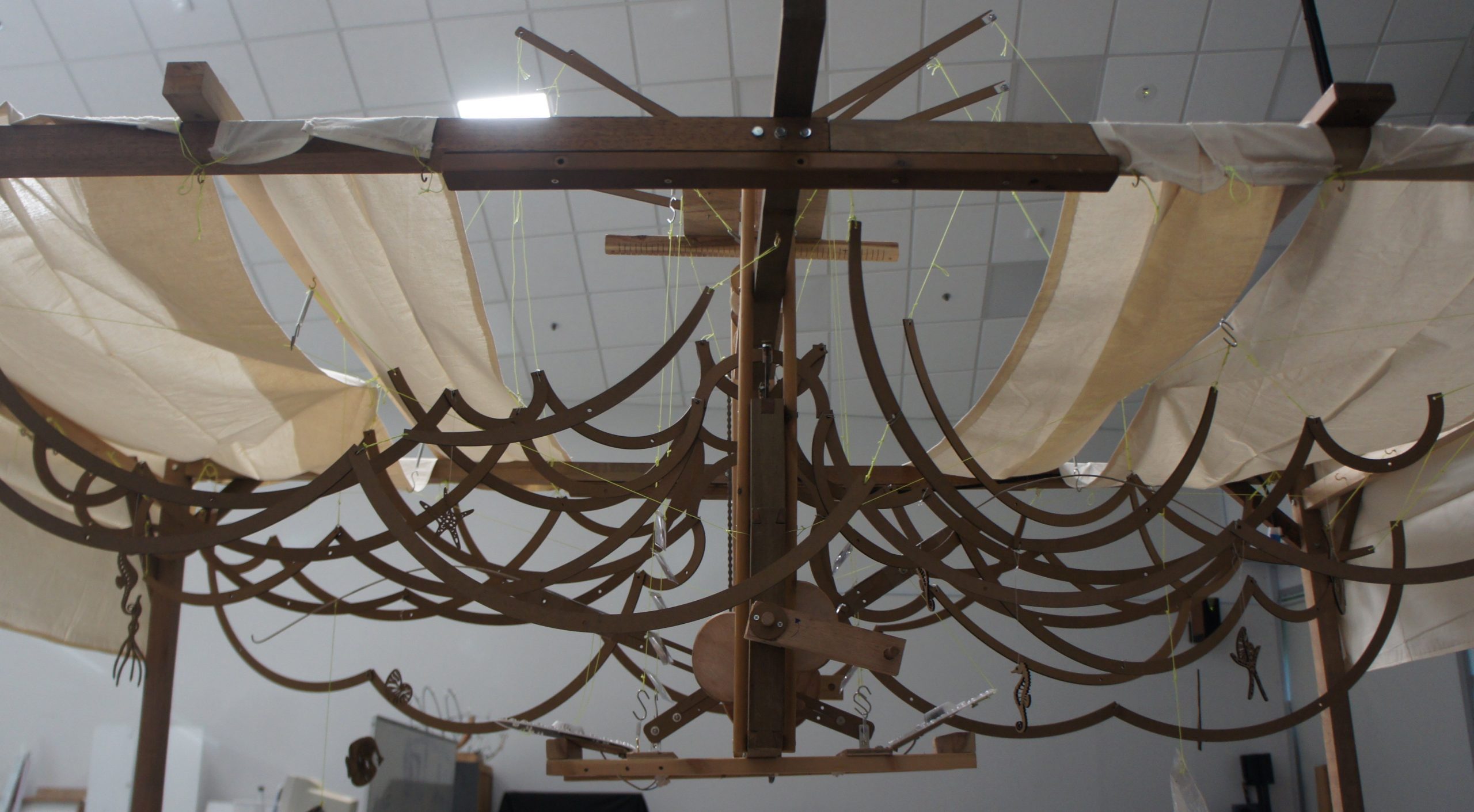
The initial concept started out as a visualisation of data points, namely the increasing mean temperatures of different continents. As I tried to work with these cam shapes, I was unable to figure out a way to make it work with the followers. So the concept was adapted to portray an ‘underwater’ scene instead, with the cams driving the motions of elements like waves, fishing rods, lights and sea creatures.
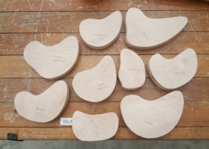
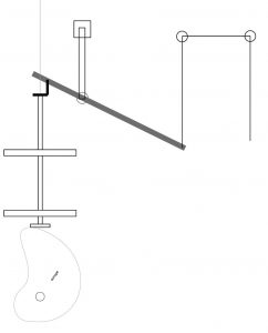

Main cam and follower section
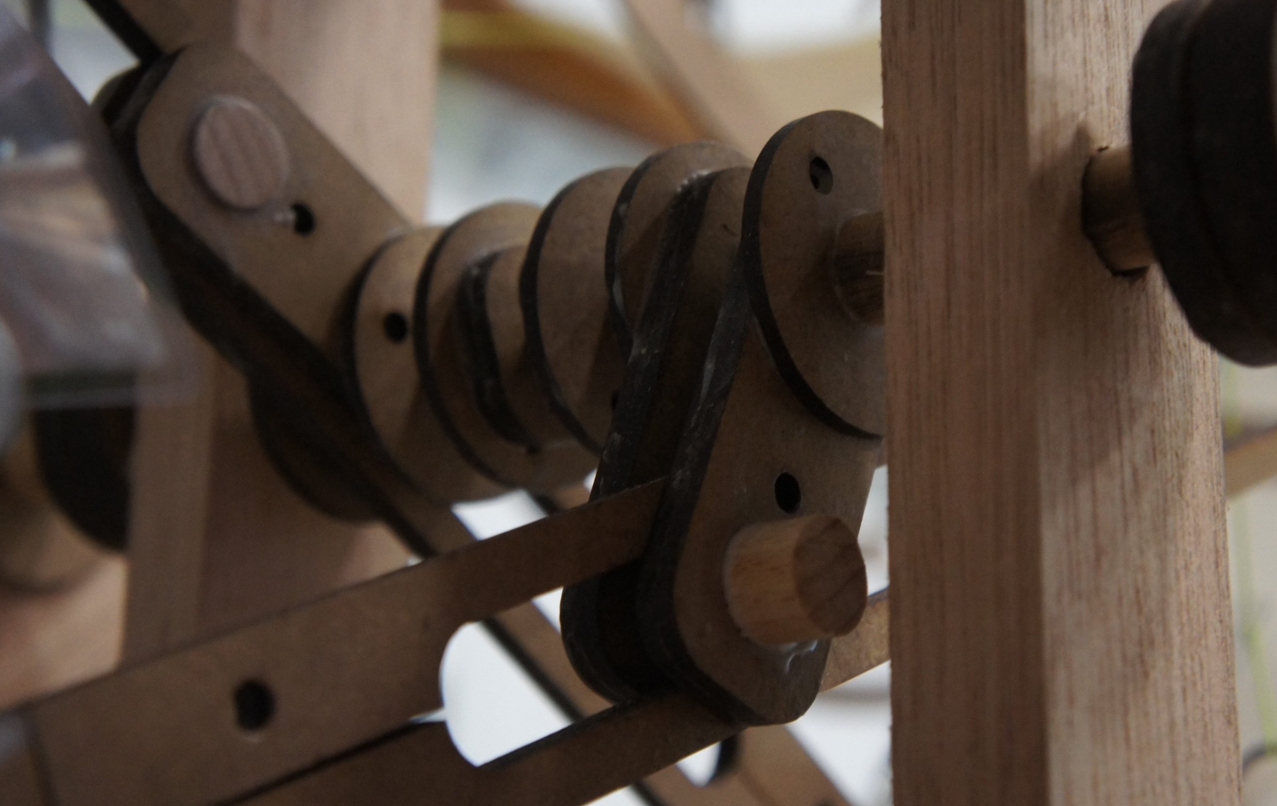
Cam and follower driving fishing rods and lights
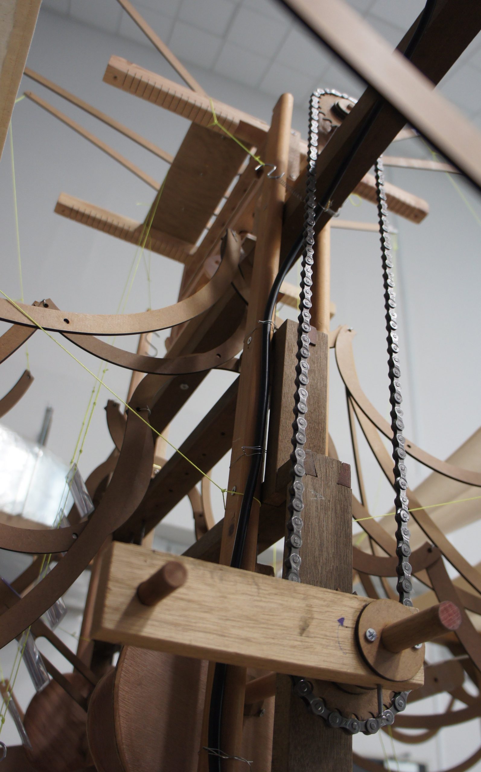
Chain connecting bottom and top mechanisms
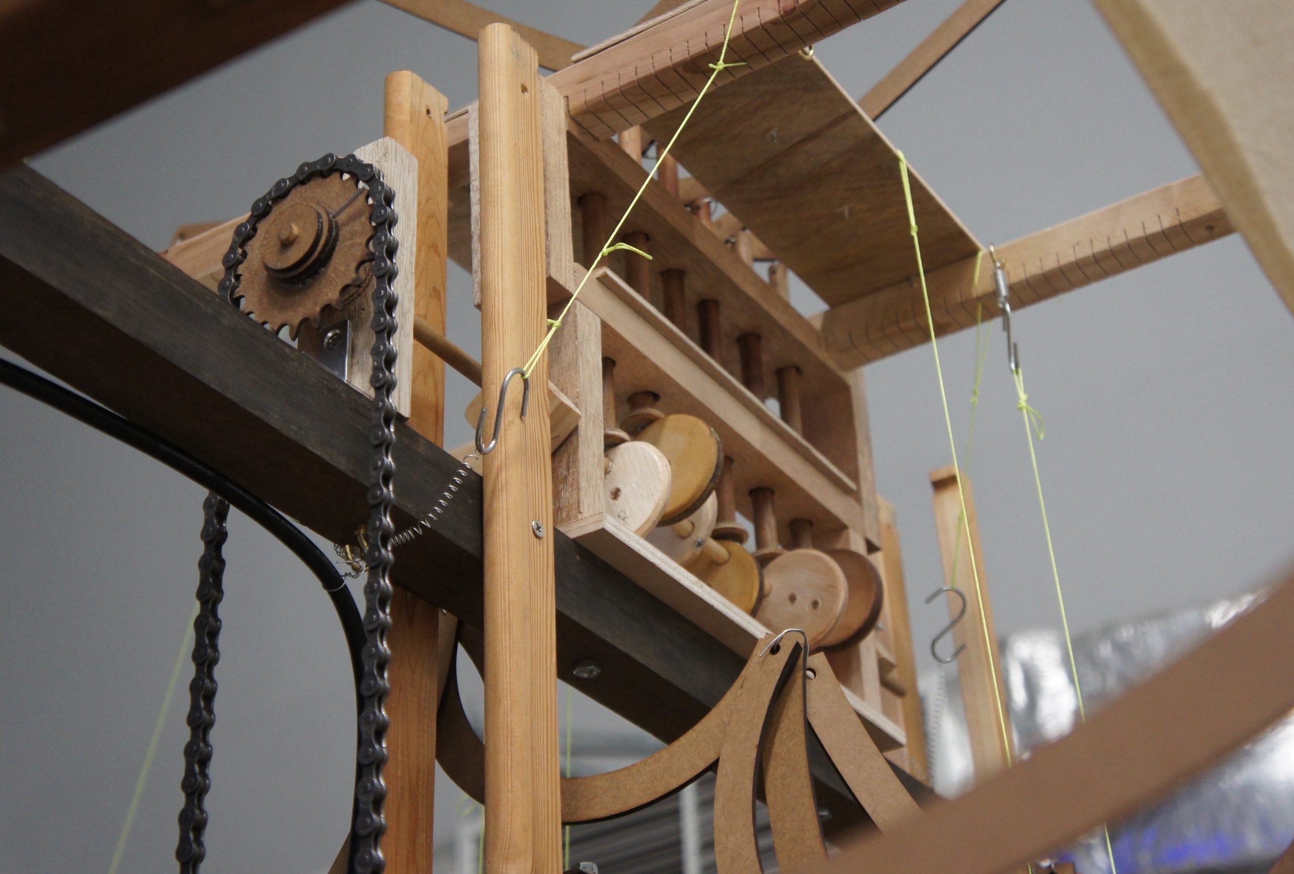
Another cam and follower set driving the movement of waves and sea creatures
The waves are connected to both top and bottom mechanisms to amplify movement and create more variations
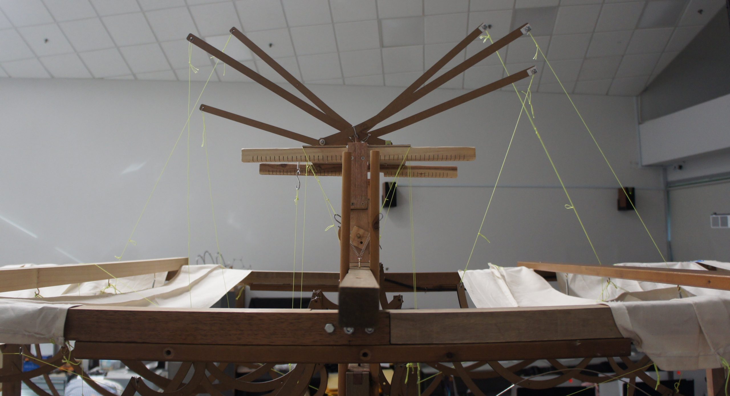
Overview of top mechanism with rods to amplify movement
Initially there was the issue of not being able to work with the highly irregular cam shapes derived from data points. The follower rods also had to be tweaked to work with eccentric cams. It was a delicate dance to get the surfaces in contact right to work(sufficiently well). There was also a practical weight limit to how much the linkages could lift, as I found out during the last stages of attaching the waves. All in all, any one part that was added or subtracted tends to affect another part of the system in small or big ways. Extension springs were also good for stiffening parts as they allow for more leeway in terms of measurement.
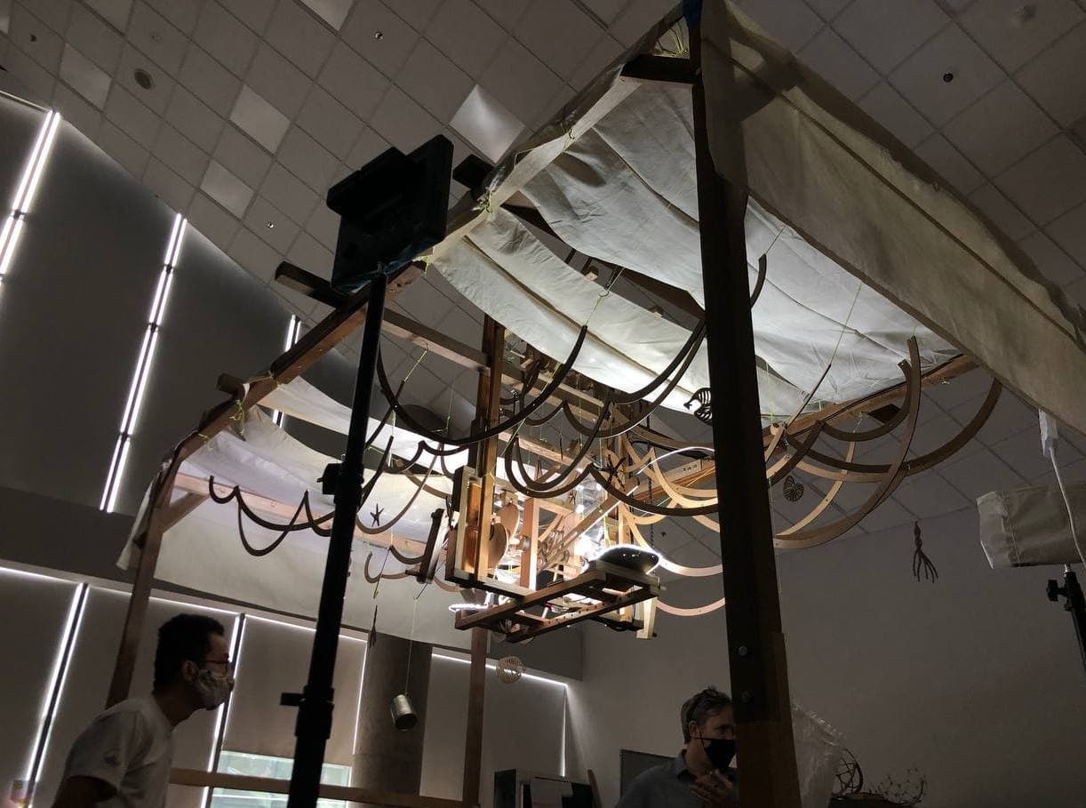
Image courtesy of Nasya
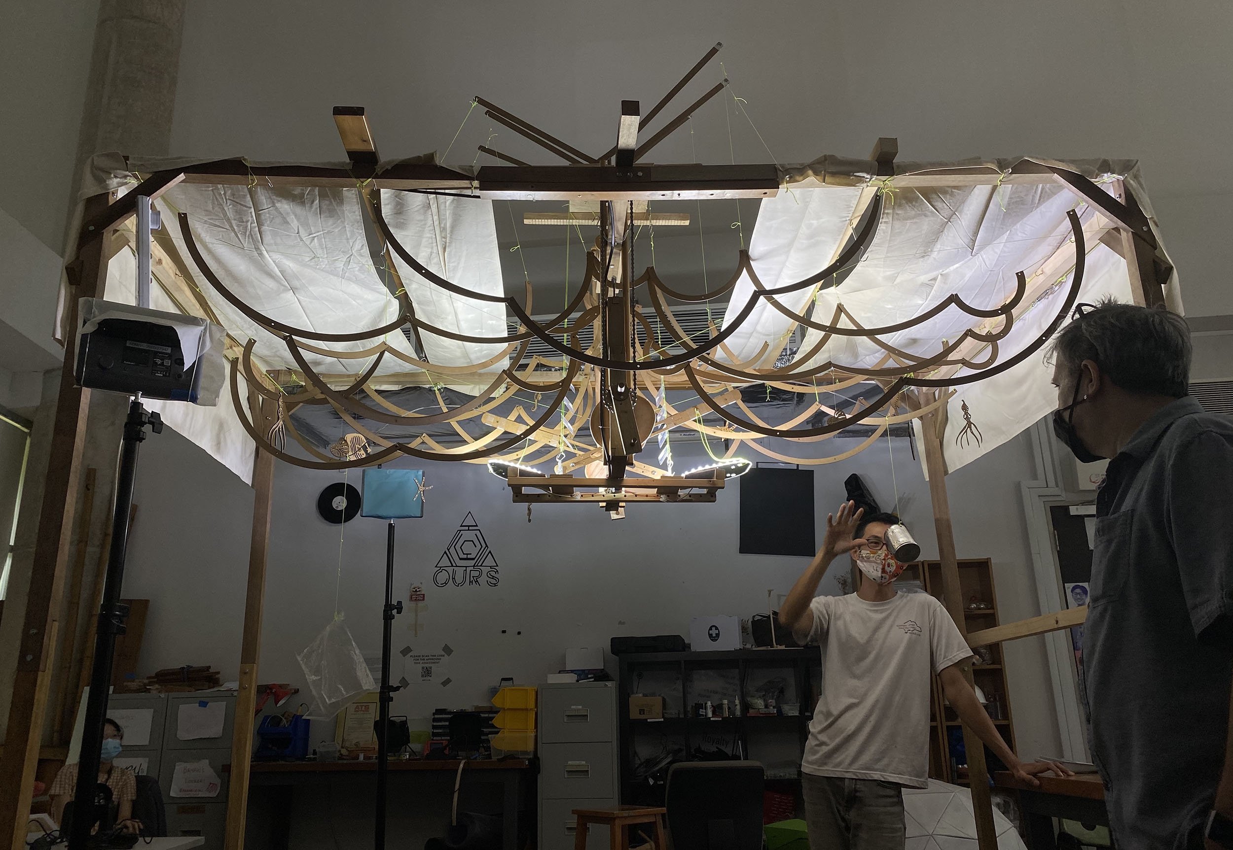
Image courtesy of Amanda
this has been a rough week, with the realisation after few hrs of fiddling that the current ‘follower’ setup cannot work with the highly irregular shapes I had produced 2 weeks before. So for now I am focused on using circles with an offset center, and produce some motion and adapt the original idea to output something visually interesting for the final.
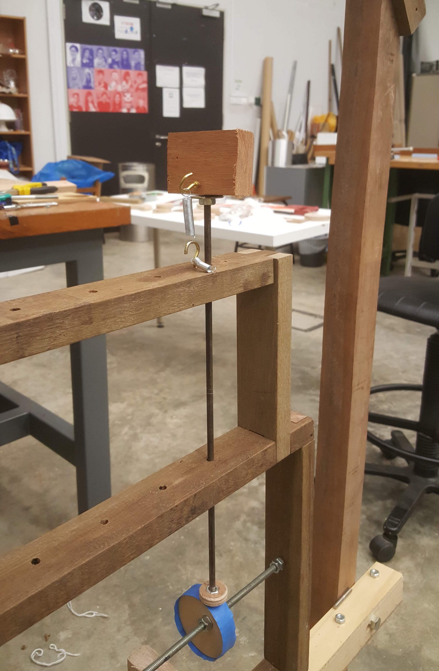
spring tests

my idealised version of leverage system

leverage test for magnifying movement
the springs are needed to bring the followers down in contact with the cam, but it’s a tricky business of balancing the strength of the spring vs the load. More experimentation time is required, which unfortunately is quickly running out.

wax helps a lot!
When the simple circles were first installed, it did not work at all. the followers were stuck. thankfully, copious wax on both cam and follower helped everything moved along.

3 test cams & added supports in the middle
after the setbacks, I decided it is best I break down the process to incremental, simpler steps and also to avoid wasting hours on producing unusable parts.
added top braces and hooks for strings
after getting 3 cams to work reasonably reliably, I placed some loads and setup the basic braces to get ready for attaching the cloth.
last week has been a roller coaster ride of sorts, first realising the original cam shapes had to be abandoned, and later the leverage mechanism I had imagined was much harder to put in practice.
also, the prototype I had constructed had too many differences from this final model. everything, from the main shaft length, follower lengths, size and shape of cams played a factor in whether it will work. the leveraging system was also non-trivial to achieve, at least with my amount of inexperience.
but all in all, I think it was a good lesson for me as all this(automata and mechanical construction) has been very new and refreshing for me, and it definitely required a change of mindset and perspective from traditional woodworking.
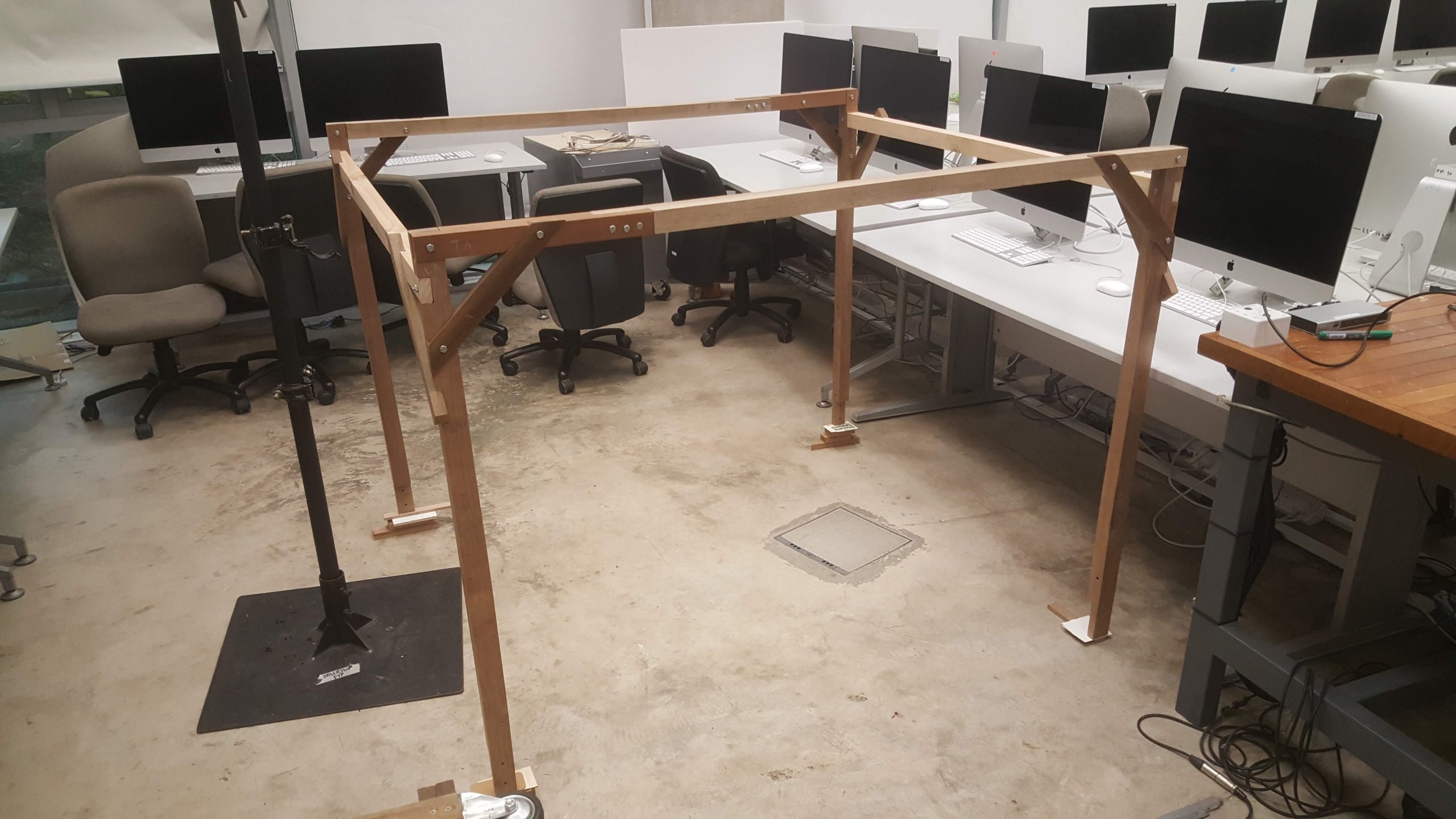
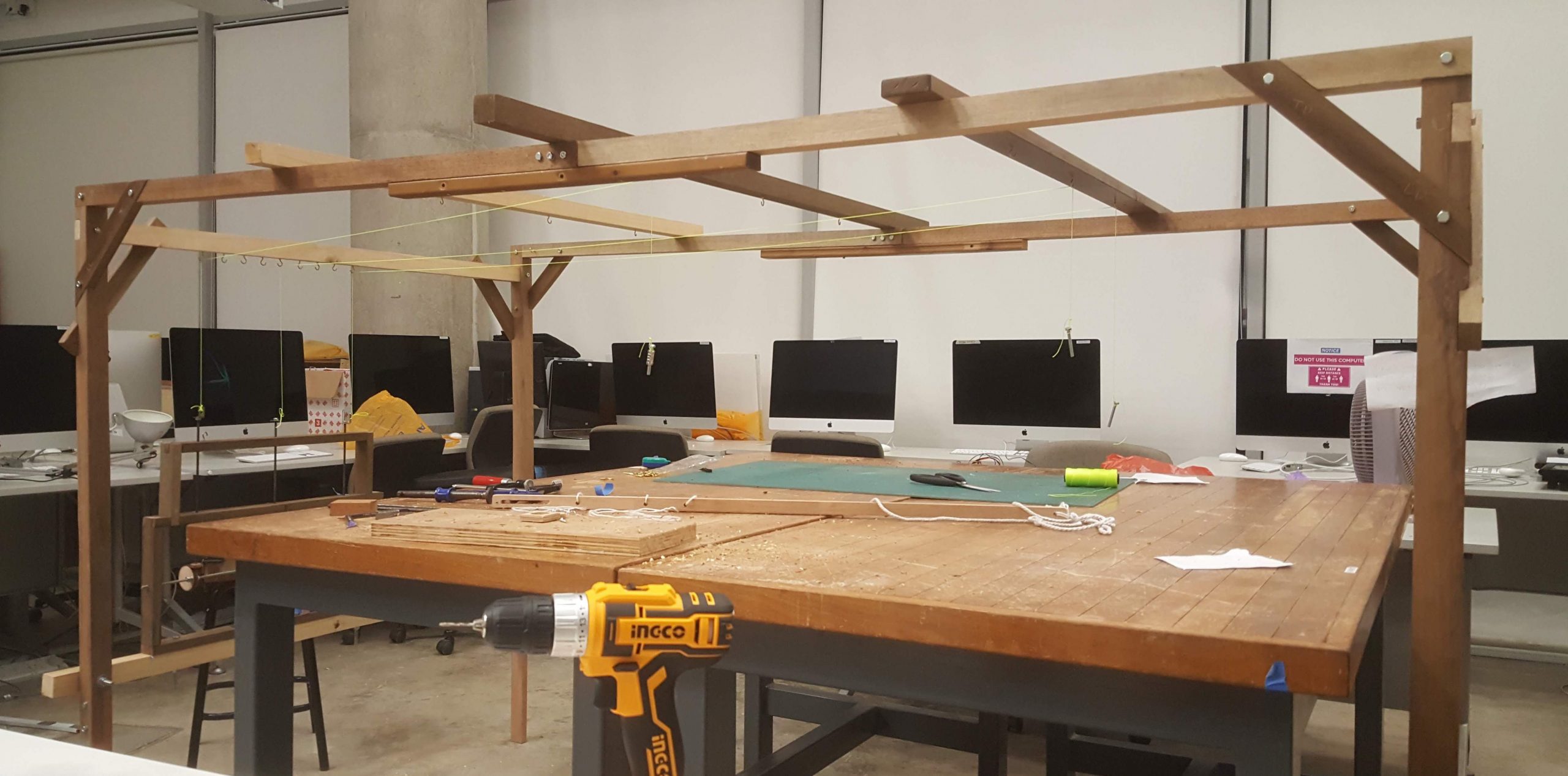
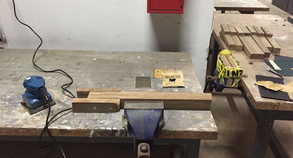
Bought all the wood i needed, and dimensioned and cleaned them
simple half lap joints for all long pieces

lots of half laps to cut
braces for keeping the frame square
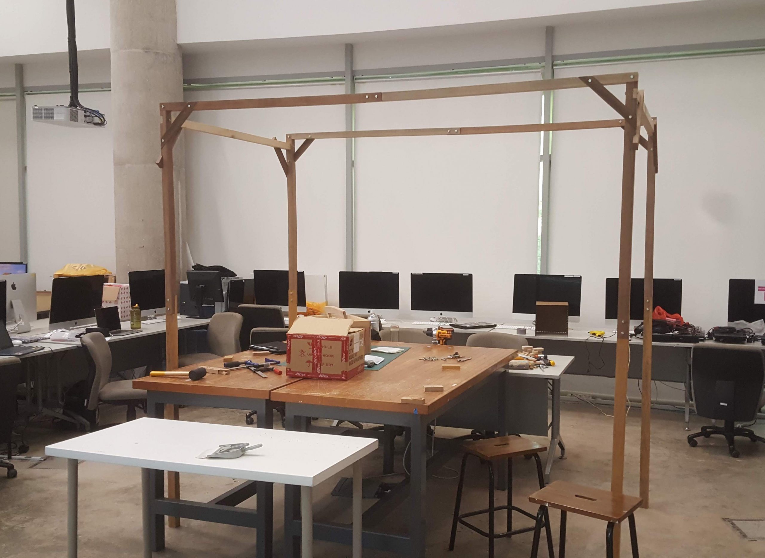
frame is more or less done, now moving on to the real stuff ?
First off, all credit to kobakant, for their amazing work. Superb repository! I am not going to talk about how this thing works, because I didn’t invent it, and also they do it much better. Hard-soft connections can be found here.
Cooking Ingredients:
Let’s try with RF shielding fabric
So to make a big mat for the final seat, of course it would be prudent to make small ones, like 3 times smaller to be exact. Some quick sewing and soldering and we are off to the races, with the WRONG material. I was just trying to be cheapskate and resourceful at the same time; used some ‘RF’ shielding material. From the test below, clearly it didn’t work. It was basically a big fat switch.
Ordered some velostat, and yes! It works.. kinda. Now just have to scale it up accordingly.
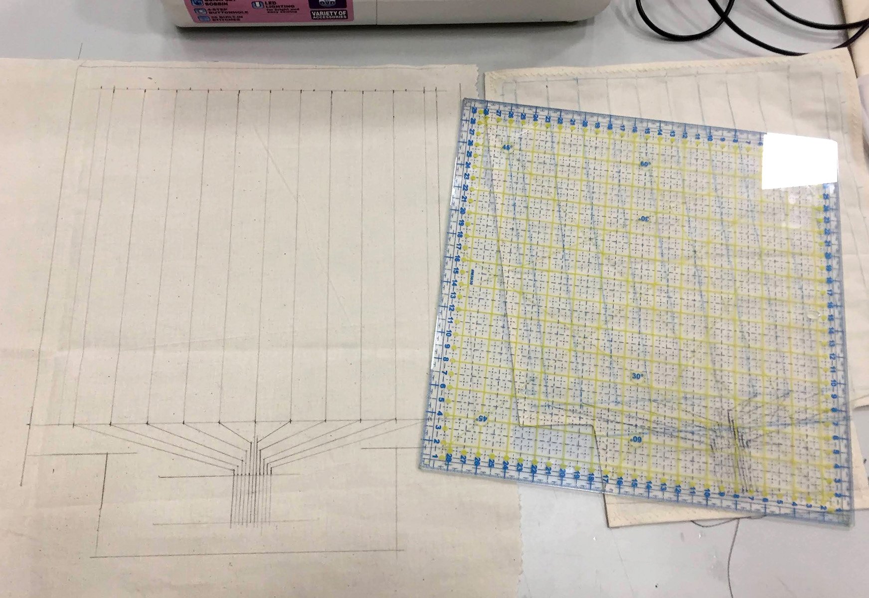
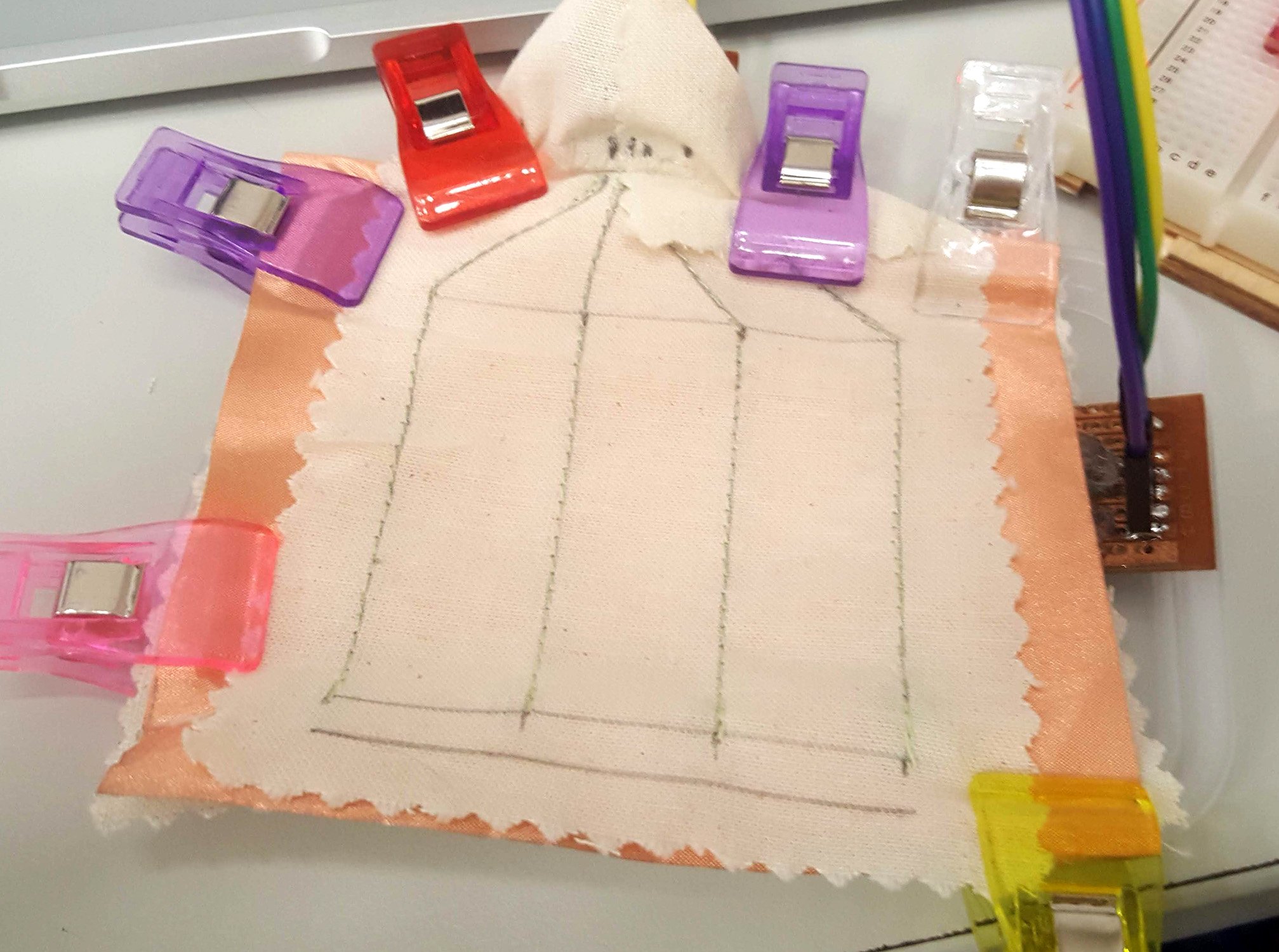
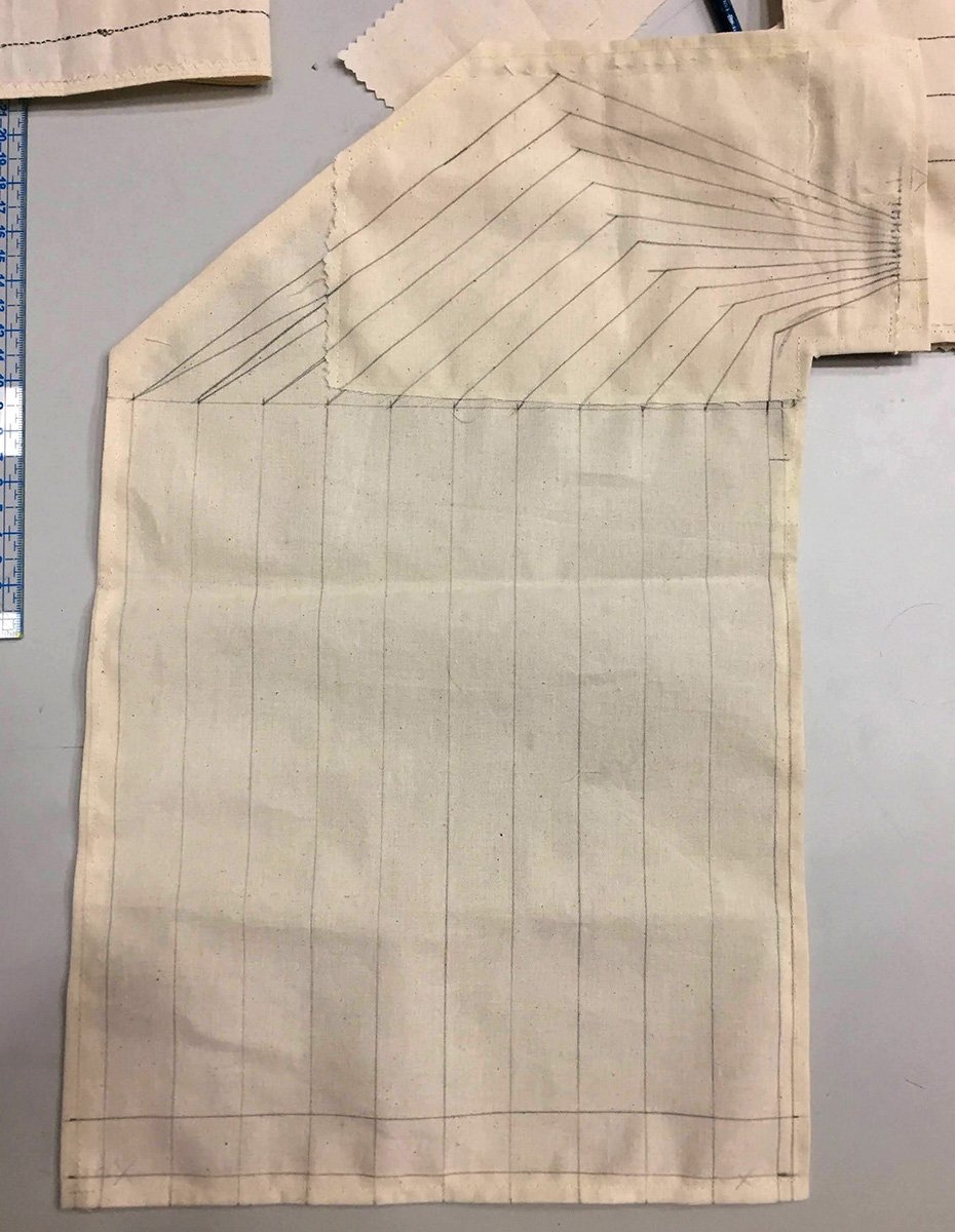
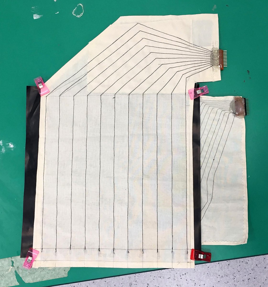
Layout
First design, I am just going with the flow and trying my best to construct a logical design. The wires come together at the end for a soft-hard transition, for easy wire connection.
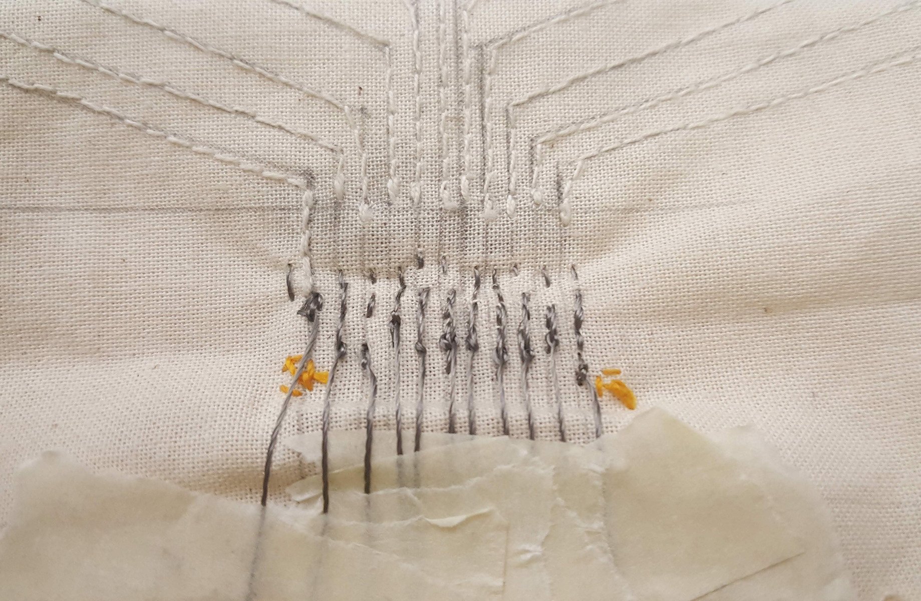
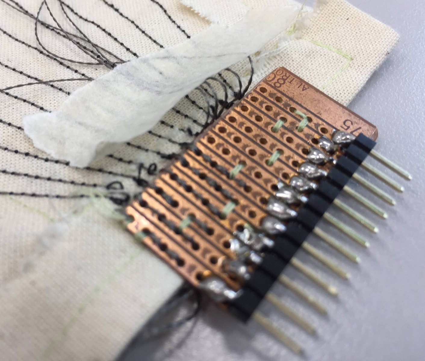
Make it straight
Important to keep the threads straight and hot-gluing them to keep in position. Also, don’t forget to always leave the extra lengths of threads on until AFTER you hot glue everything. Only trim when the hot glue is set, duh…

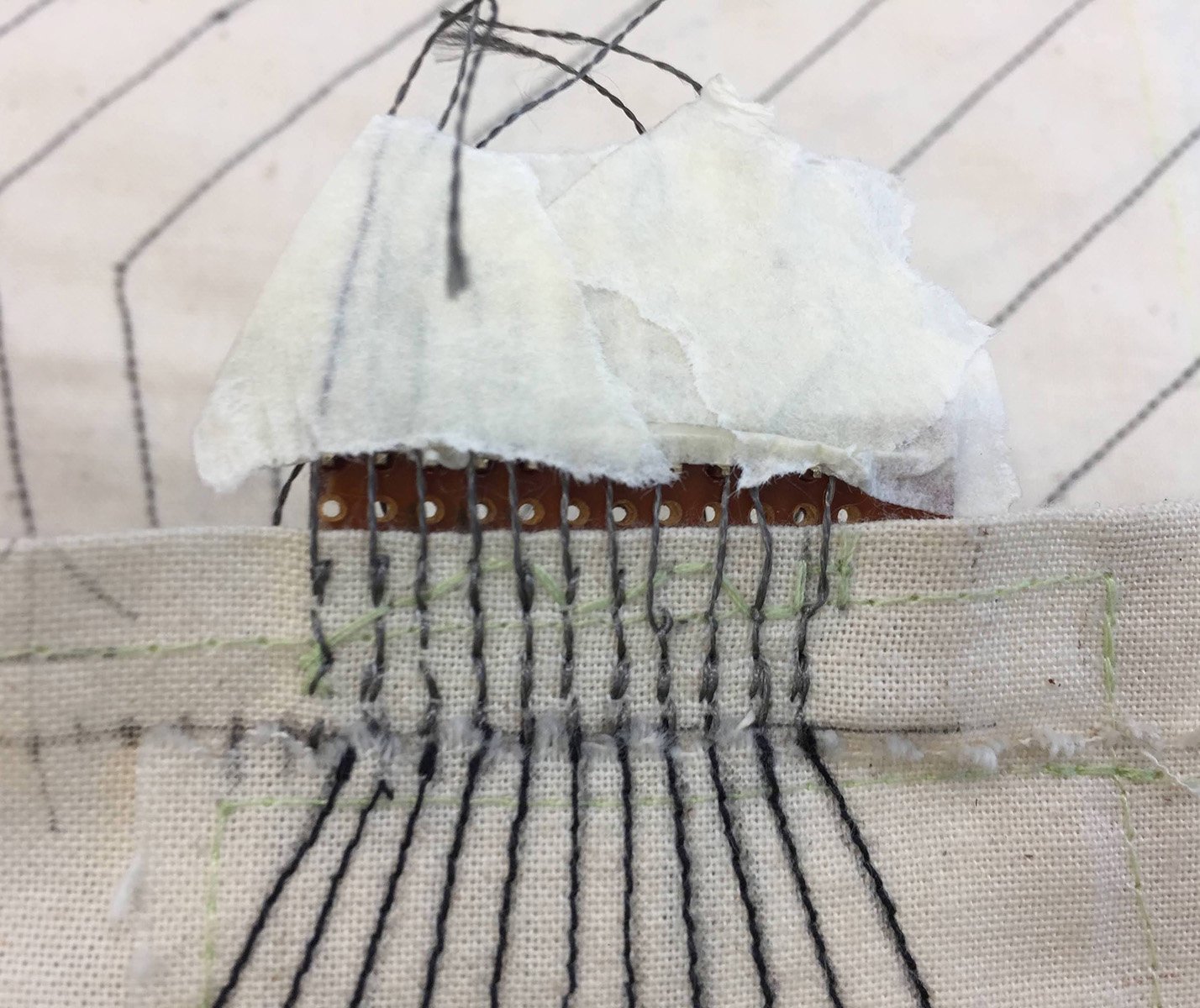
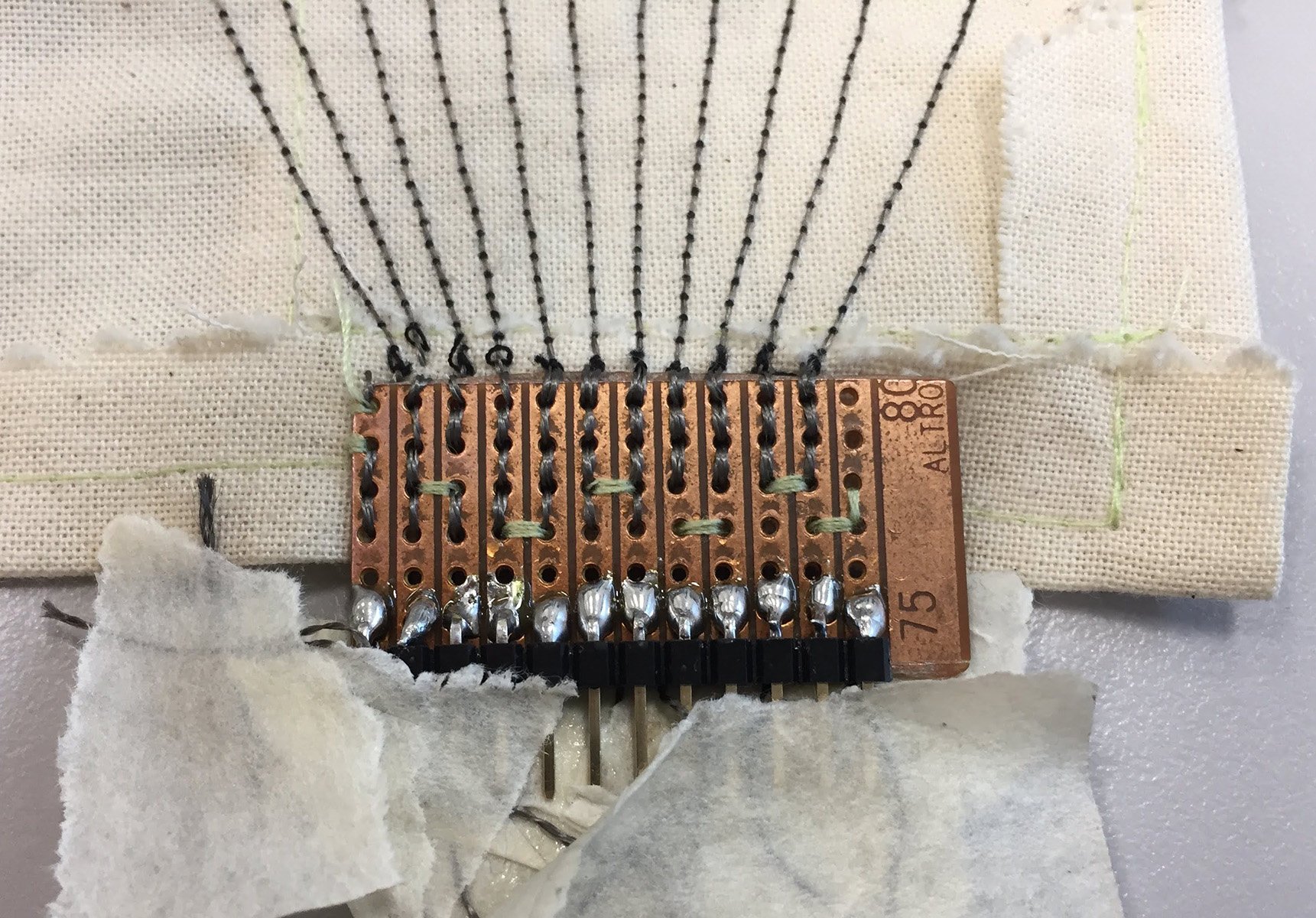
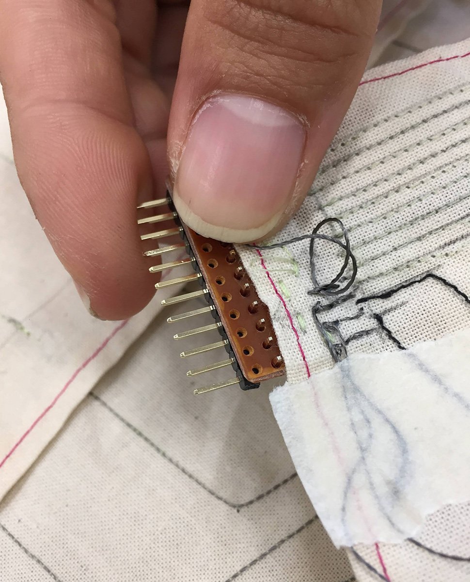
Soft-to-Hard transition

First decent finished piece!
Obviously, this wasn’t the first full piece I made. In fact, the third. Few things I picked up. The conductive thread shouldn’t be too thick; makes it hard to do everything. Ideally 2-ply would do. And always leave plenty of thread at the end for easy soft-to-hard sewing. Experimenting with 2-3mm stitch spacing, I felt that 2mm gives a neater result, and doesn’t really use much more thread; not sure about thread usage actually 🙂 .. Also, I made the terminals face same direction for both pieces, for obvious reasons …
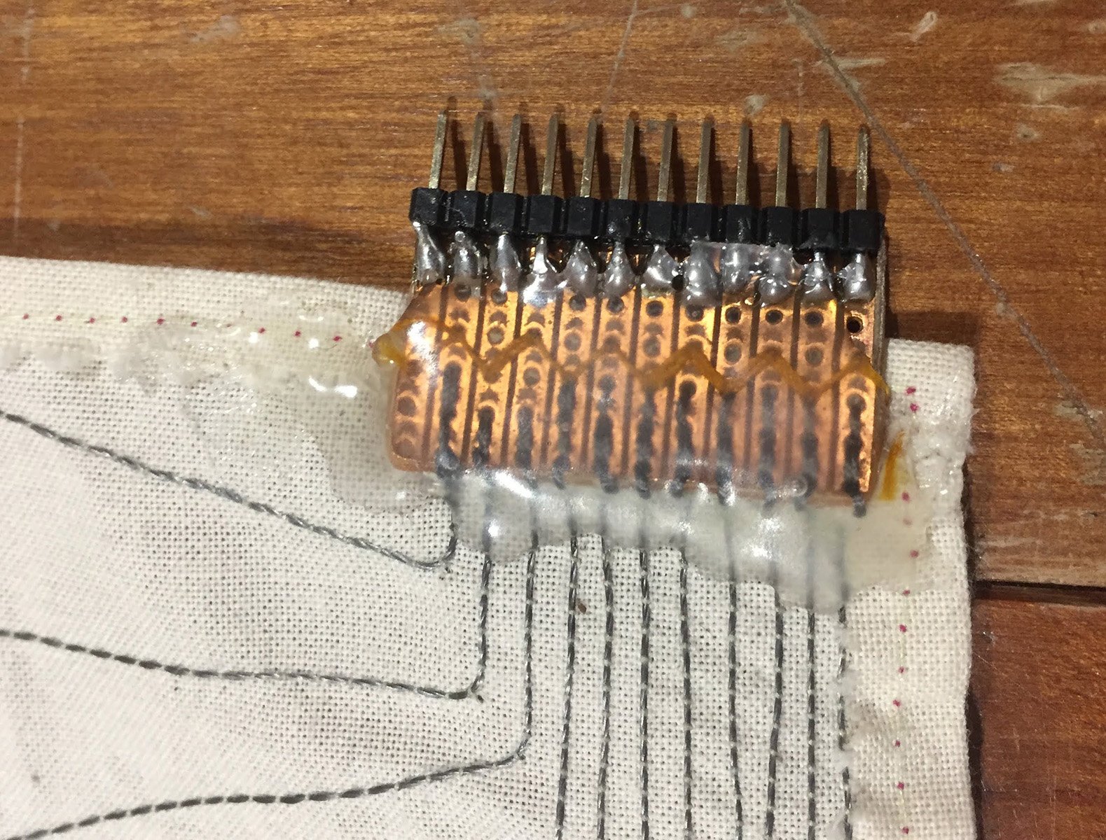
Hot-glue keeps it neat
Yes, hot glue does solve everything in this case. I really don’t think it’s possible to make a reliable product if you choose this type of connection.

Buttons for easy removal
To ‘attach’ all three pieces together, I decided against stitching as I wanted to make the pieces as serviceable as possible. So I used buttons instead. This way I can simply button the sensor onto the chair seat.

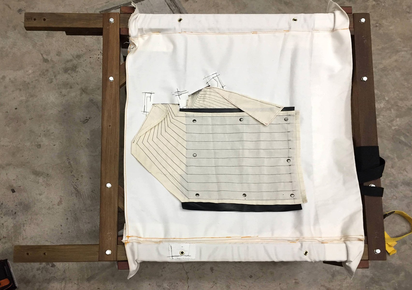
Positioning on seat
Positioning by eyeball, I am guessing most people will sit at the bottom 1/3 of the seat, and also because my sensor is only 27 x 27cm; due to the size of velostat I could procure. But I figured technically I could cut out strips of velostat and sew them onto the stitching, so I could increase the mileage of the velostat use. I’m playing it safe though as time was tight.

Slits for cable relief
Slits are required for the terminal ends to hang loosely so that nothing breaks when 100s of pounds are applied onto the sensor. Small strips of fabric are used to reinforce the sides of the slits in an opposing direction.

Fitting complete !
Sitting on it and not breaking anything was a sign of relief. Now I just need to go through the whole process and create the second piece.
Top layer for beauty sake
Before I could test run, I had to solder lots of wires; nope, the crimped ones aren’t going to cut. I ran a count, and am proud to say that I did over 100s of soldered joints by the end of the project. But I still had to rely on hot glue 🙂

Lots of connections in this batch; 96 in total!
Here you can see it kinda works, it’s a little noisy and off in accuracy at certain parts. But otherwise I am glad that something even flashes..
New layout; maximize wire spacing ?
As I am making another set, why not have some fun and experiment a little? So I decided to try out a new layout and see if I can notice any tangible difference. Here the layout is for maximizing wire spacing, so that I can delay the tiny spacing as long as possible, but it does burns your pockets…
Practice makes perfect?
Getting neat and tidy joints take time; 1-2 hrs on average!
All done, hot glue to tie up everything

new layout all done, last piece as well!

no knot necessary?
Tying knots mean the thread length needs to be more, which equals extra cost. So being cheapskate me, I struggled with tying knots while having short ends. But I realized that you can get away by just having it loosely looped while pulling it through, but does require a finer touch.
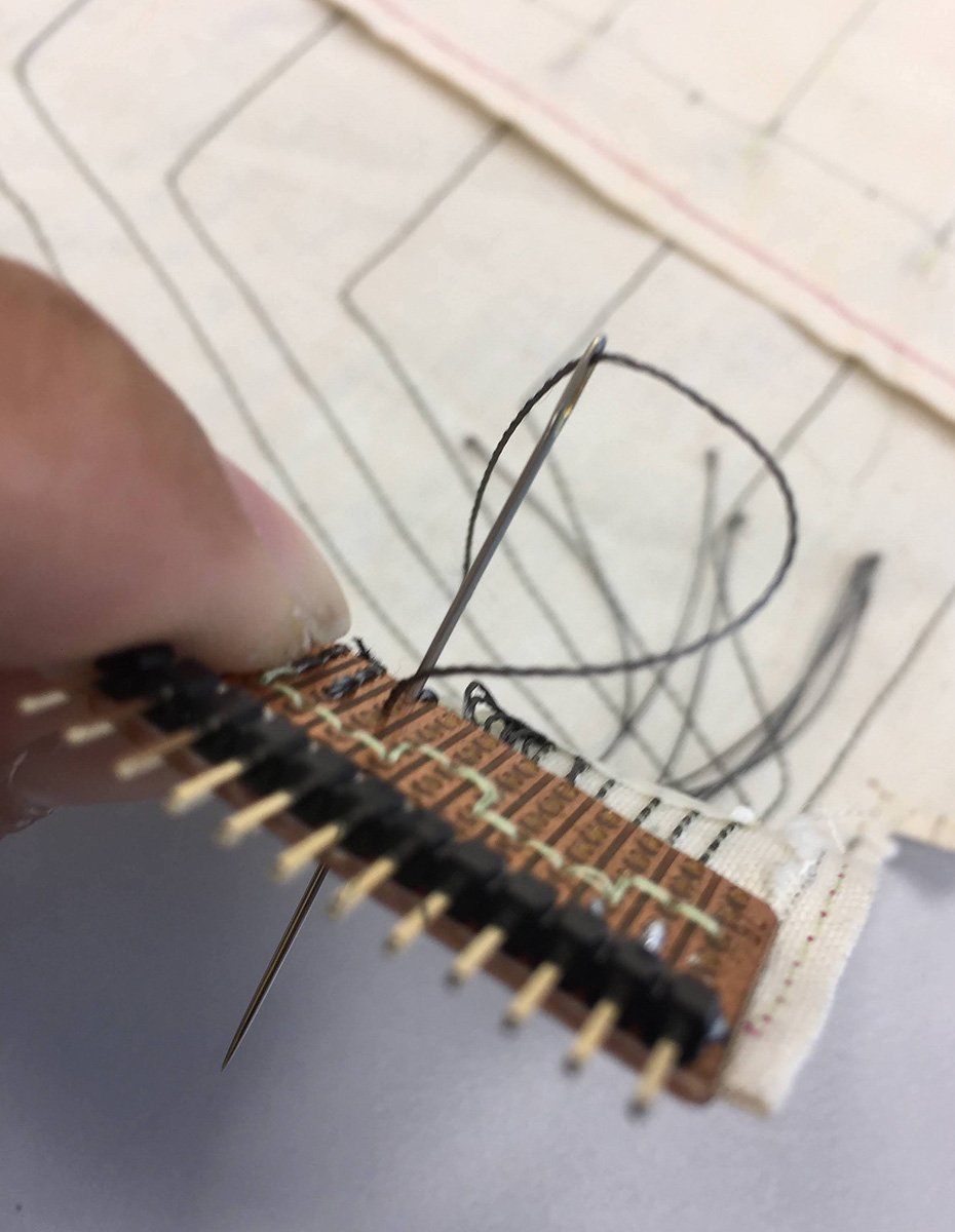
needle just needs to pull thread thru
Tie a knot! You can never tie too many knots when you are doing e-sewing.
be sure to tie a knot !
wala! second set done
I must say, this second set seems much improved. In appearance I mean.
Second set integrated onto chair, support strips added at wire terminal areas
Last stretch, the sensor is integrated and we are done

makeshift arduino platform, with barebones cable relief
Simple makeshift board for mounting the megas, with tremendous cable management and strain relief.
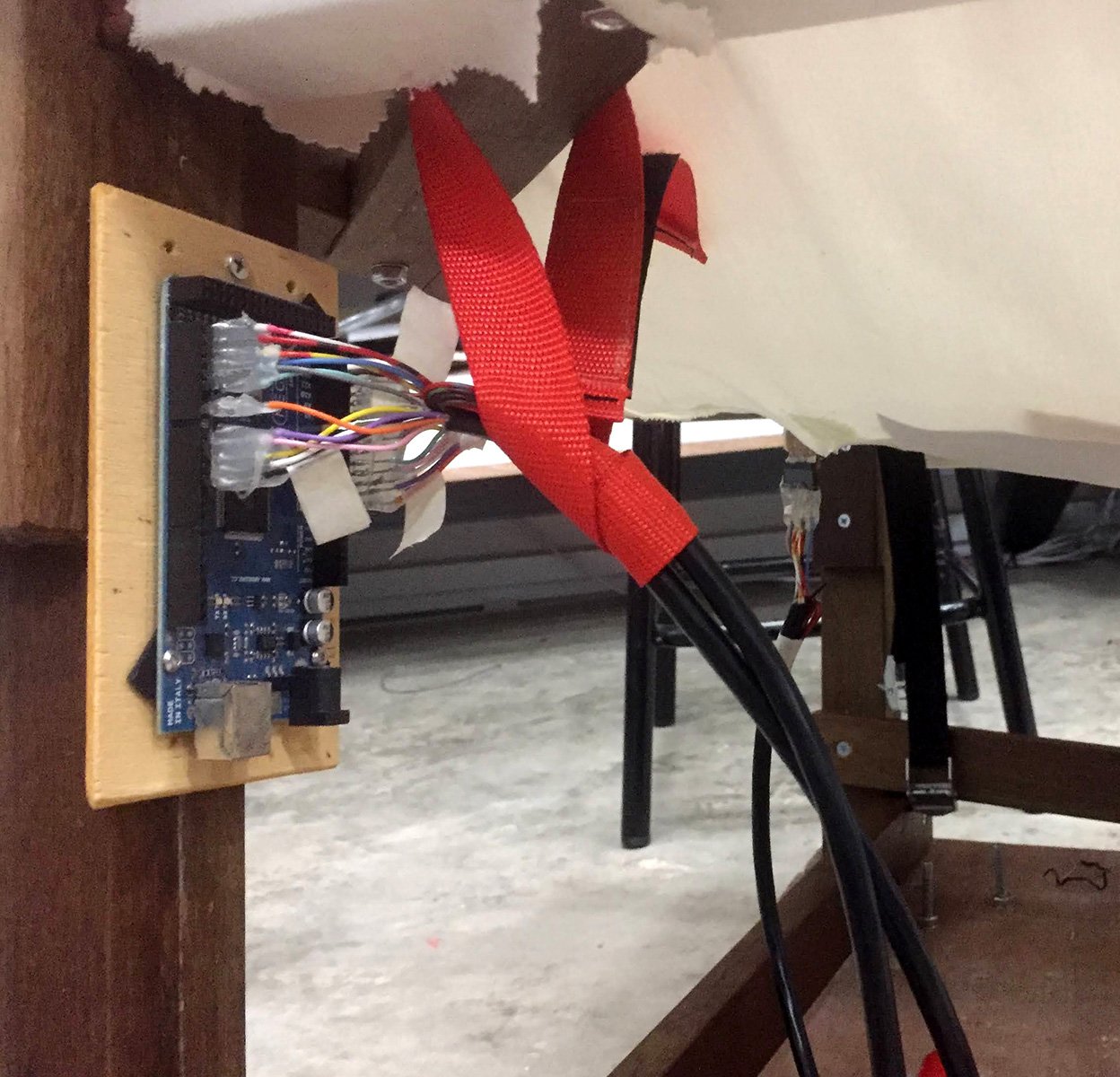
cables start and end wires labeled for easy install
But mine doesn’t. Touchdesigner is all the rage these days, and I have no intention of bucking the trend.
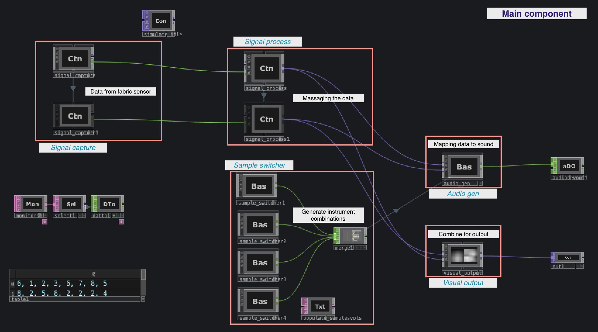
Bird’s eye view of the whole setup
I try to modularise as much as I can so that the logic can be made/fixed independently, OOP style, so to speak.
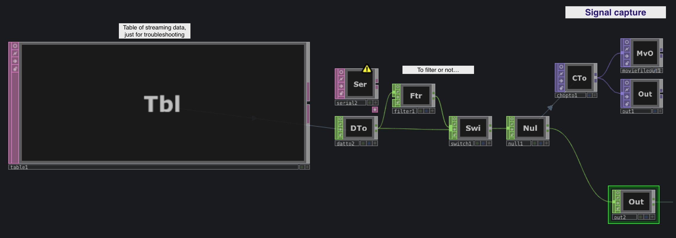 This module simply receives data from Arduino and converts it into a usable format. TD is receiving the serial data in rows, as I tried sending all 121 values all at once but doesn’t play well.
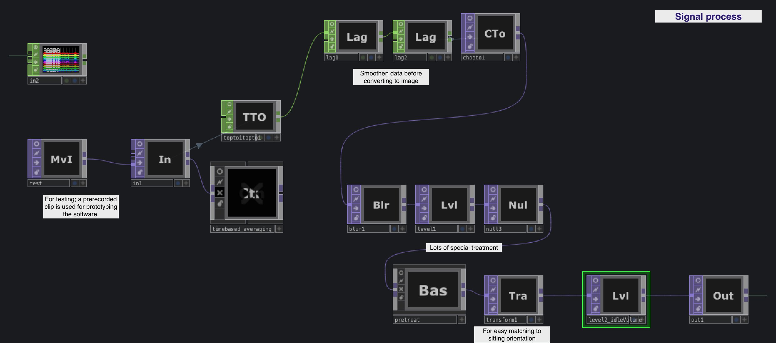 The data is pretty noisy, partly because I believe of the many imperfections of the homemade sensor, and also the lack of calibrated tests based on the conductive threads I used. In short, lots of data fixing before it’s in usable form.
 This part is simply to automate the process of changing instruments/sample combinations every set interval, so that I don’t have to pay someone to sit there and press a button. Also, I can experiment with combinations and add/remove them easily.
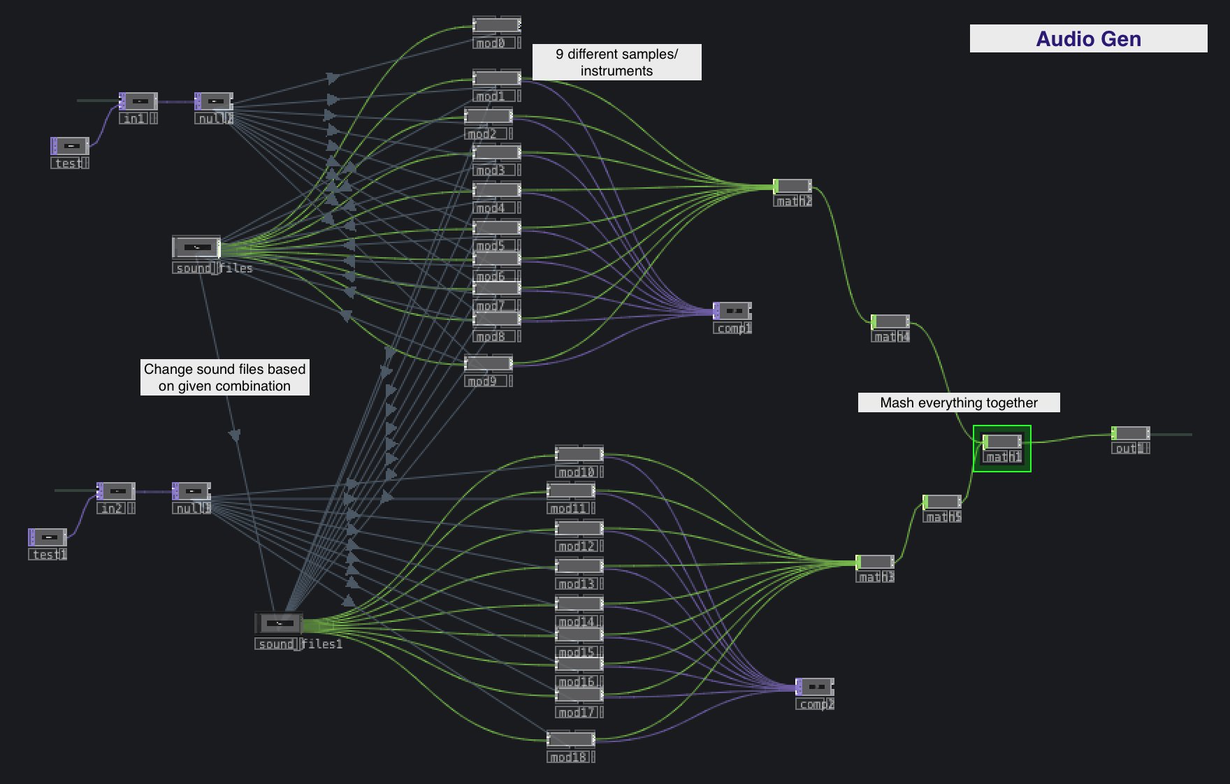 Many connections, but it’s because we are dealing with 2 chairs, and each chair’s sensor has 9 spots that correspond to 9 different sound files. TD makes it easy, and very fast as well.
 Here the sound files are switched out according to what combination is selected. Again, TD has made it easy; here I am switching between 9 sound files x 8 combinations = 72 files, all achieved with some dragging and dropping.

Here the outputs from the sensor visualisation are combined, and I have added a ‘watercolor fx’ just for added visual interest. and partly because the iMac has enough muscle to run everything at 60fps.
The day has come for showcase !

Special mention(again):
Sensor Fabric based on work & research by Kobakant
Special thanks to:
I started the design in CAD, after having a loosely similar sketch. In the first iteration, the sitting area was much wider, basically a 1m x 1m square. After all the design was done, I prepared a cutlist, and upon realising the ridiculous amount of wood the design required, I had to go back to the digital board and do major revisions.
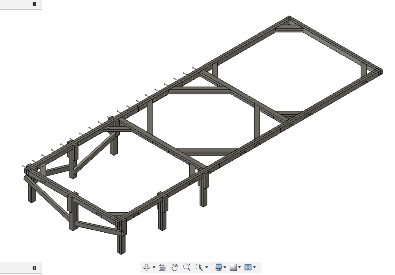
Design Iteration 1
I first down-sized the sitting space to a cosy 60cm x 60cm square, and reduced the number of legs. I was pretty confident this amount of wood was structurally sound, as I have made sofas of similar design before(actually slimmer in design). I was very relieved when the updated cutlist reflected an almost 30% reduction in wood requirements. On hindsight, I am glad I downsized the structure as the timeframe was challenging enough as it is.
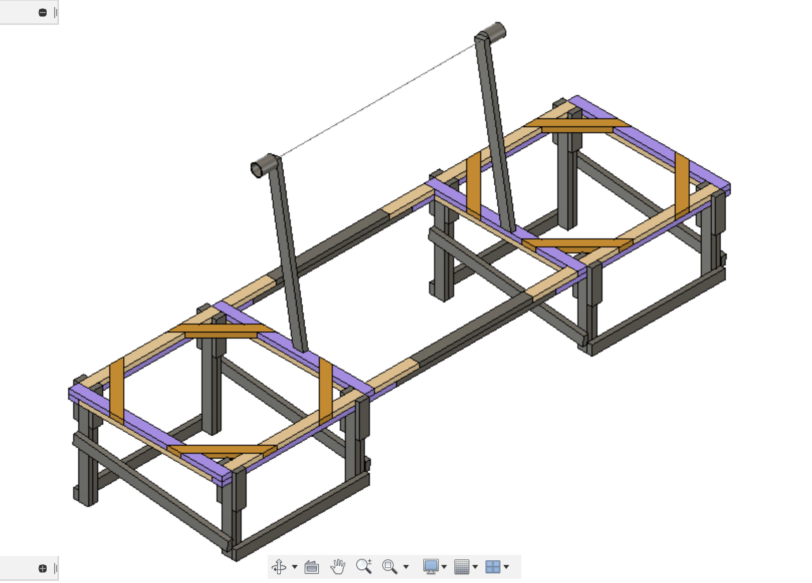
Design Iteration 2
The building of this project took place over an intense five days, at least for me.. But it was great to do some building from time to time, and I am proud to share my process..
The wood was all sourced kindly from the IM room; alas there were many twisted ones, but as a lot of my construction used short lengths, much of the twist was mitigated as I processed and glued them up. Also, I would like to add that the whole process involved no heavy machinery, 🙂 only a cordless drill and sander.
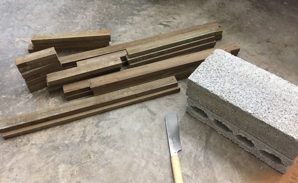
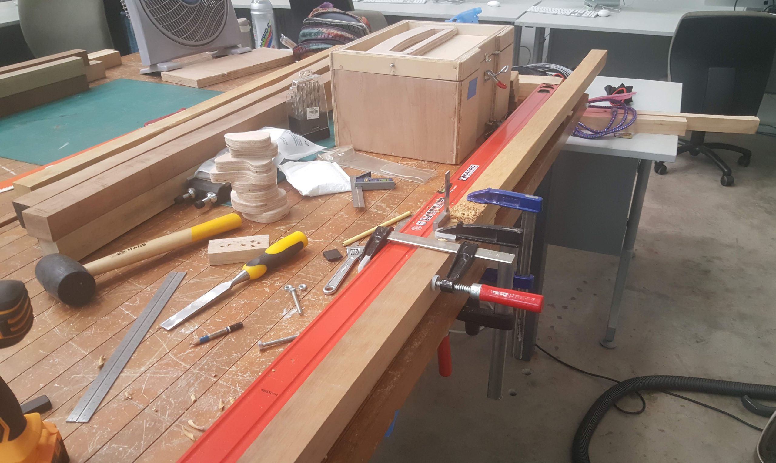
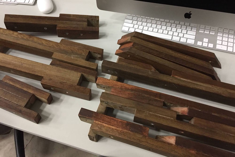
Cut planks to length
Measuring, cutting alone took a full day, in total there were close to 80 pieces, derived from about 6 x 2.4m planks. Then the planks were fitted, cut and glued according to the CAD design.
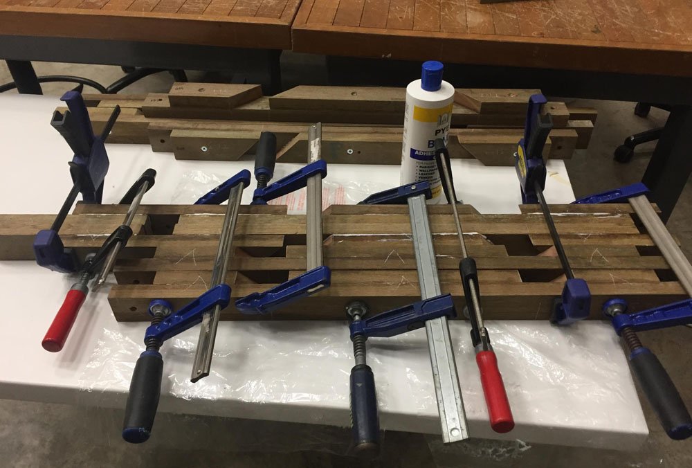
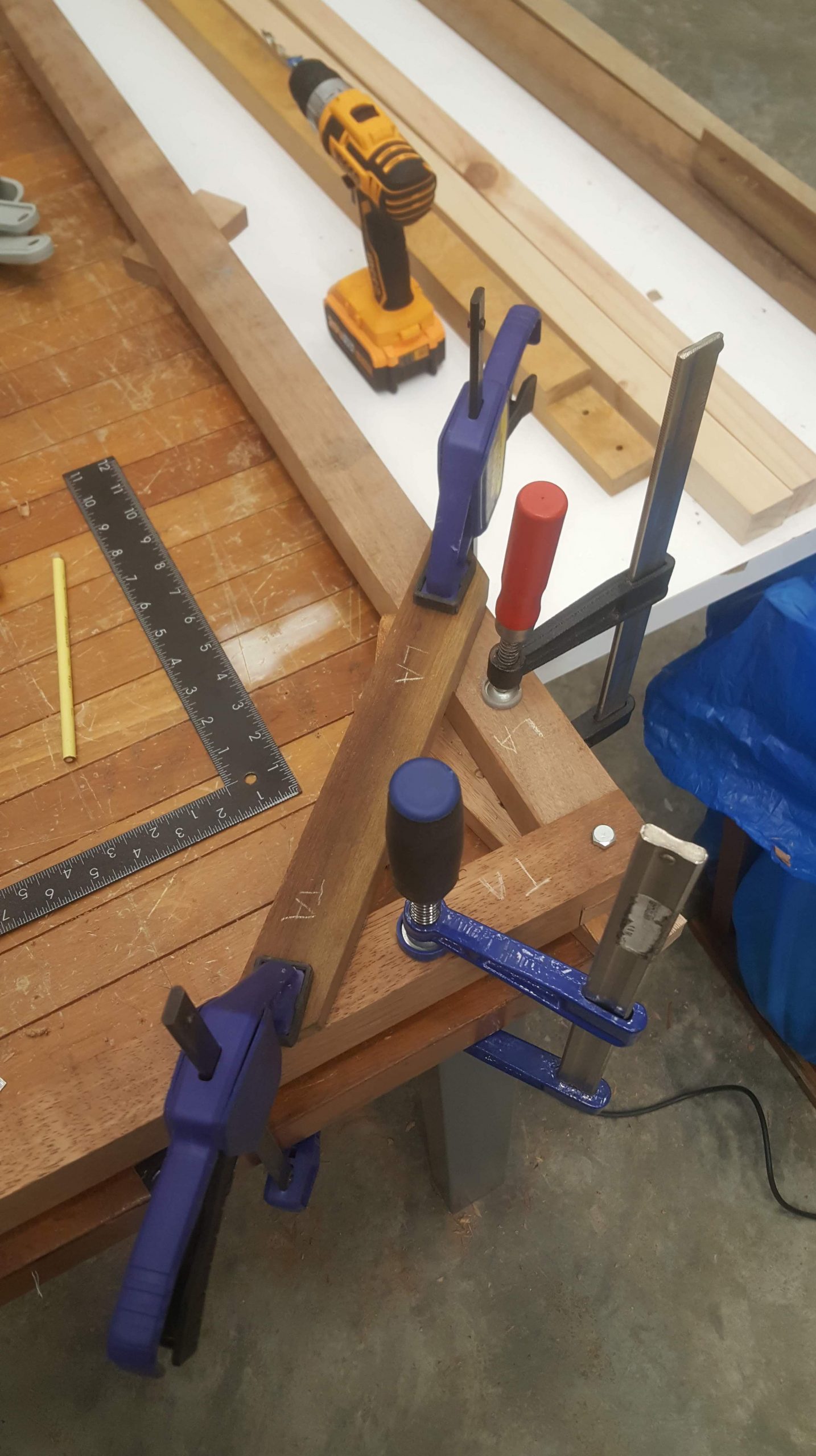
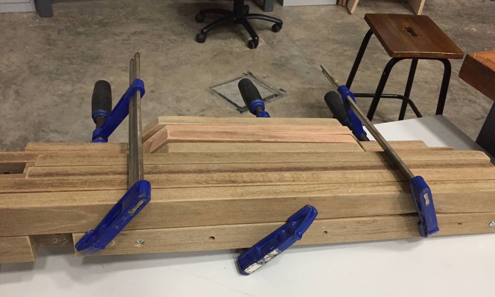
Glue planks for strength
When one half of the frame was done, a dry fit was done to make sure that the translated CAD design worked in real world. At this point it was pretty spot on. Though I must admit the frame was not entirely square; about 5mm longer on one half.
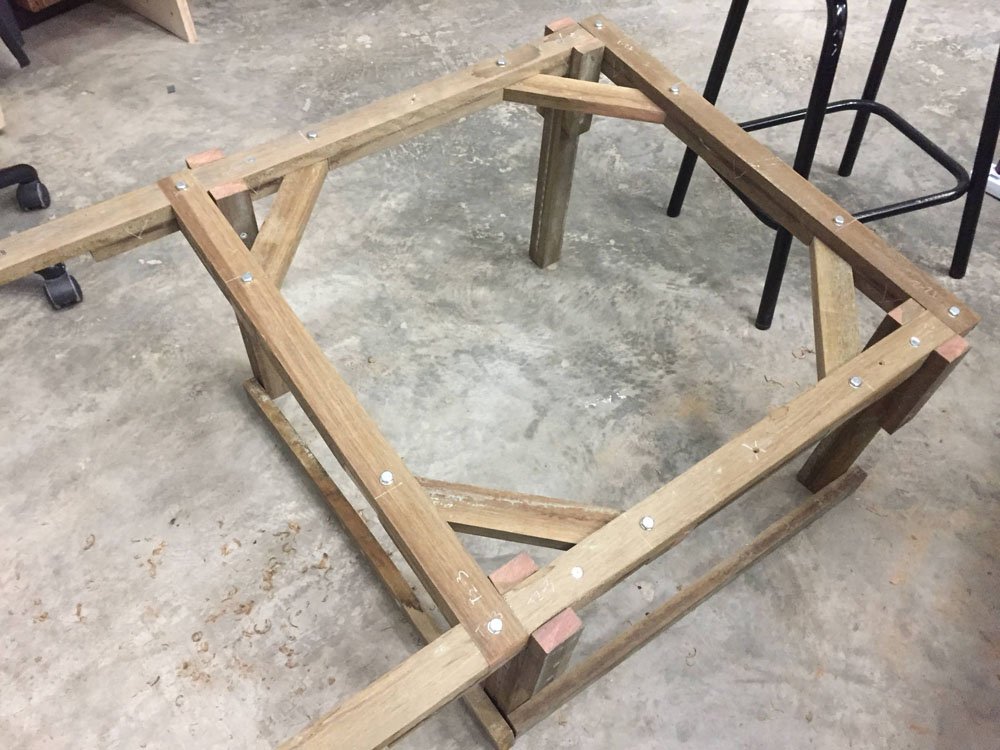
First rough framing complete
After all the parts were ready, lots of sanding was done to remove the blemishes and cracks in the wood. This part was certainly one of the most demanding.
Sanding mania
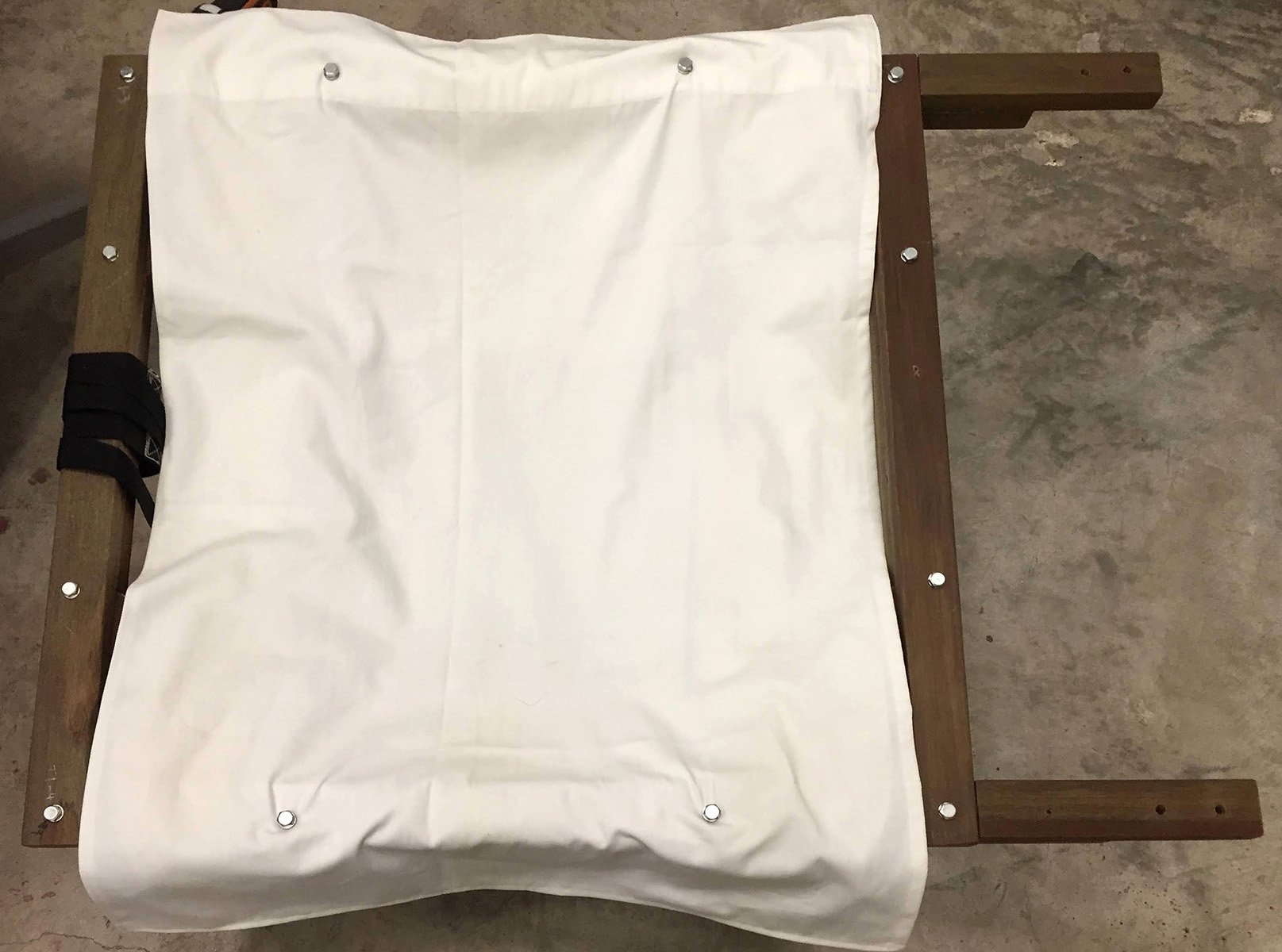
With the framing ready, the time has come for throwing in some cloth for the seating. I had on hand some used curtains; these were plenty strong for our purposes. After a bit of trial and error, I made 2 straight stitches on each side to act as sleeves for them to slide onto the frame. I try to make this as modular as possible, so I avoided using staples, even though it would be much faster.
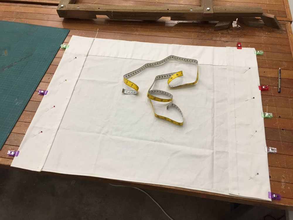
Marking & sewing stitches to cloth
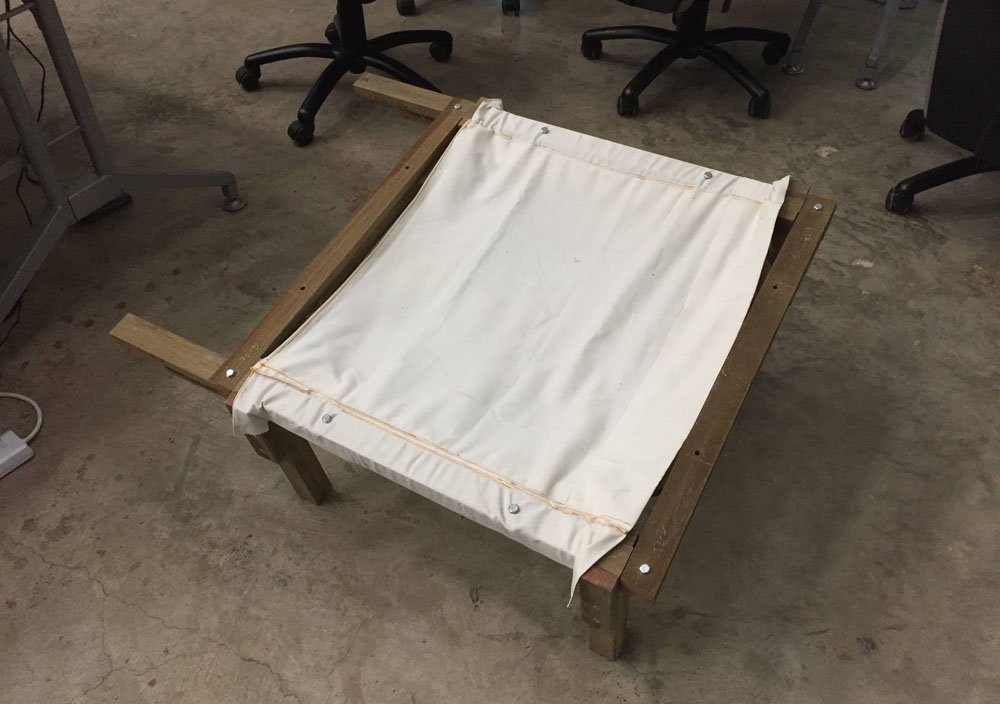
Fitting cloth to frame
As there was plenty of sanding to be done, I sanded one half per day and applied wax so that I can use the time while the wax is drying to sand the other half. It was pretty gratifying to see the crappy wood transform into something that look somewhat luxurious 🙂 By the way this is kapur timber.
Applying wax finish on first batch of sanded parts
Finished all sanding ! This is how the planks look before wax
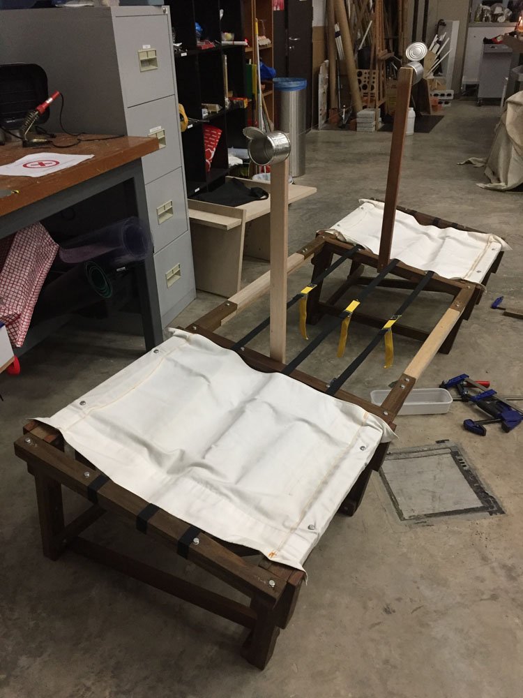
Moment of truth! A first full assembly of one half. The legs are properly fitted for the first time, with the addition of the bottom leg tie supports. I deviated a little from the CAD for the supports, as it didn’t negatively affect the strength and looked more visually interesting, seen here in a cascading style. Some sewing was also done on the straps, repurposed from cargo tie-downs. Three of these were more than enough to help support the weight of seaters. Bryan, Zhifeng and Bao also bravely helped me test-run the strength of the cloth seats. Seeing Bao sit comfortably on the chair, I was confident the structure could handle itself.

First full assembly of one side, sign of relief!
The other half was done much faster, and after some finishing touches the whole design is fully realised and ready to go! It was Friday, so I decided to also quickly throw together a cart to house the dismantled structure, and get it all packed and ready to go for installation on Monday evening.
Full assembly complete
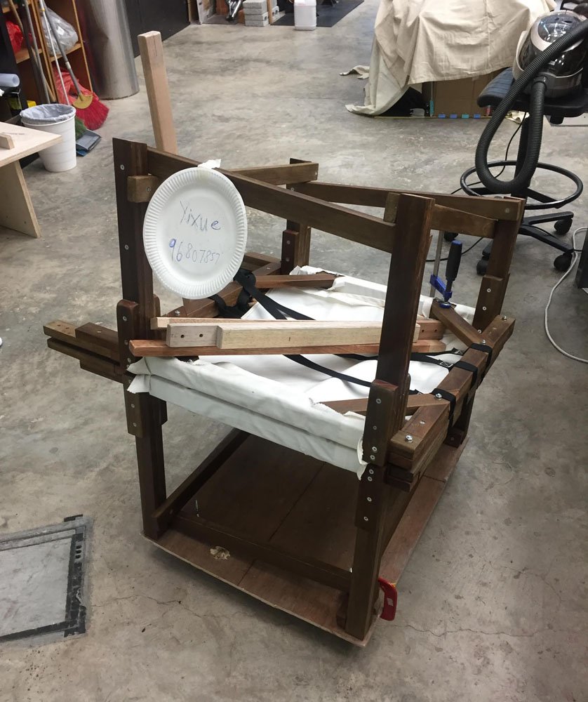
All packed and ready to go
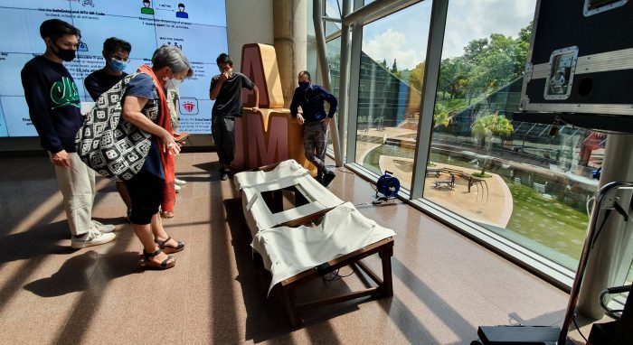
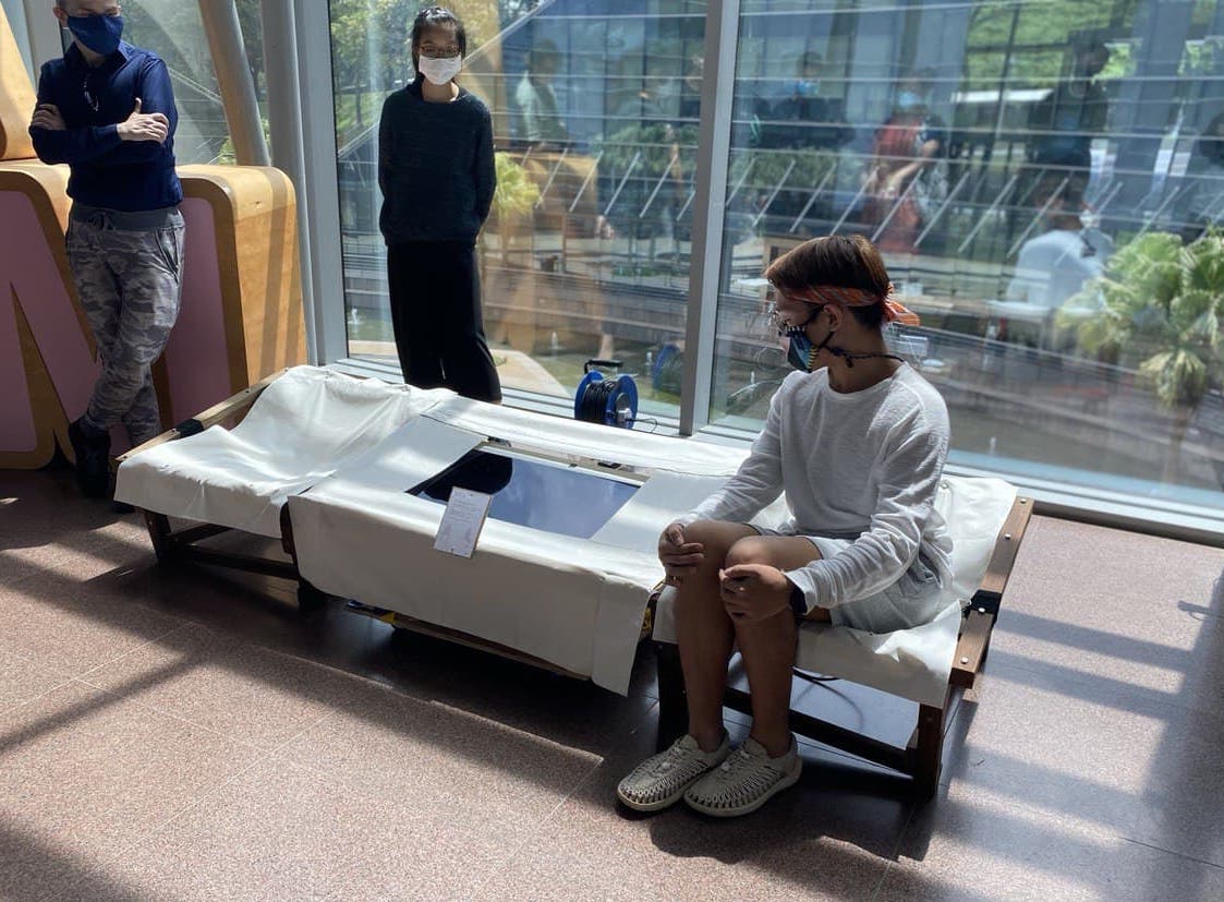
Setup went by smoothly, as this is an analog project I guess? Digital projects tend to throw you curveballs. I also added some greens for good measure. I was lucky to have Gwen, Yenee and Amanda to help me test-run. I am glad they had a bit of fun.
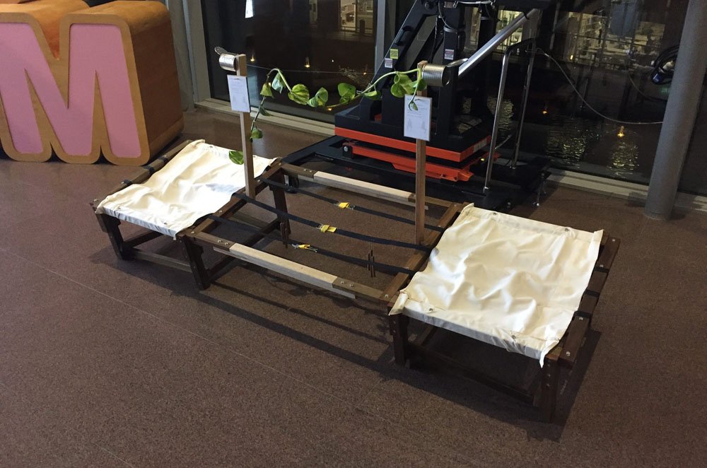
Setup at location

First eager participants :p
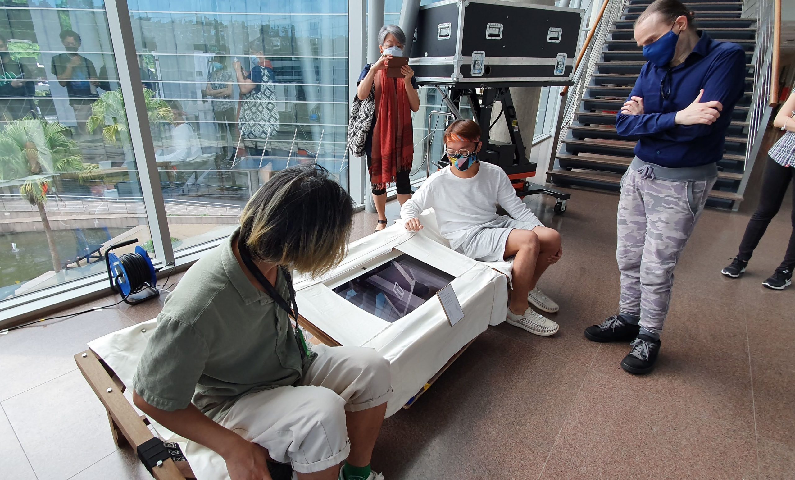
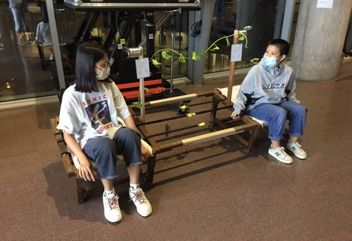
Presentation day. In general I think the structure held up well. In terms of interactivity, it was limited. Most of the interaction occurred as people sat and got up, making it see-saw-ish. Also, the tin-can contraption was more of visual eye-candy than functional. I think there are many opportunities for further development. And hopefully for the next iteration we can have this outdoors for better effect.
Cheers !
Critique day