
About Project
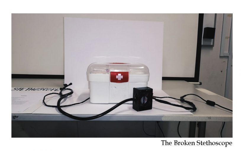
The Broken Stethoscope is a physical representation of the vulnerability of strained relationships between 2 people. These strained relationships are usually caused by emotional abandonment of one party, leaving the abandoned party in confusion. However, when trying to solve this abandonment, the abandoned party is often faced with silence, and a lack of interaction. In the perspective of the perpetrator, this silence can root from a lack of understanding of the other party’s situation, or not wanting to risk the negative consequences if he/she answers.
Me and Mun Cheng thus decided to use a stethoscope as our object. Similar to how a doctor checks on his patients, we have the perpetrator and the victim doing this interaction instead, where the victim asks the questions to the perpetrator.
Observational Documentation (user-tests)
Videos
Design Process Documentation
Initial Ideas (please click the attachment below)
IDEAS FOR EXPERIMENTAL INTERACTION FINAL PROJECT
Process documentation
Initially, we wanted to install the stethoscope head below the Peltier module (which we encased), but we realised that the sound of the cooling fan overpowered the sound of the heartbeat, thus we decided to remove the stethoscope head altogether and just replace it with the Peltier.
Final Presentation
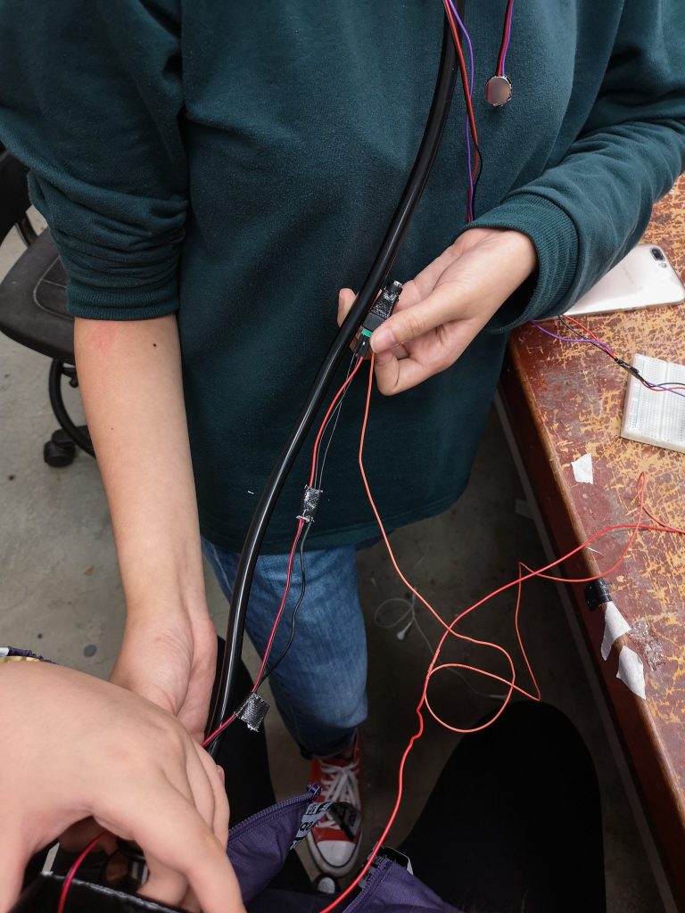
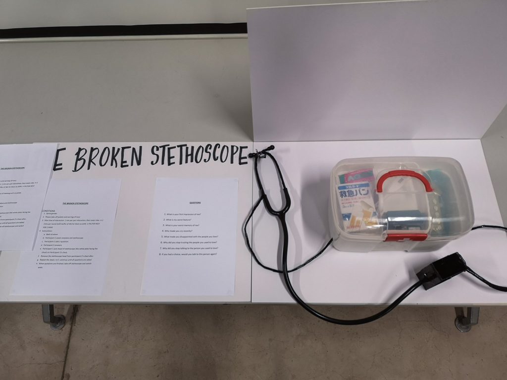
For our final presentation, we created a set of questions for the two participants, The participant who is wearing the pulse sensor is the one asking the questions, and the other participant who answers feels the coldness from the Peltier module. We also gave disclaimers and instructions, such as to take out any jackets and earrings so that the pulse sensor can be installed properly, and that the participants can feel the coldness.
Instructions and Questions (please click attachment below)
THE BROKEN STETHOSCOPE instructions and questions
Instructables
Materials required
- Peltier module
- Heat sink
- Cooling fan
- AC to DC power adaptor
- Female power connector
- Pulse sensor
- Breadboard
- Relay
- Arduino module
- Laptop / power bank
- Electrical tape
- Thermal paste
- Stethoscope
- Acrylic
Step-by-step
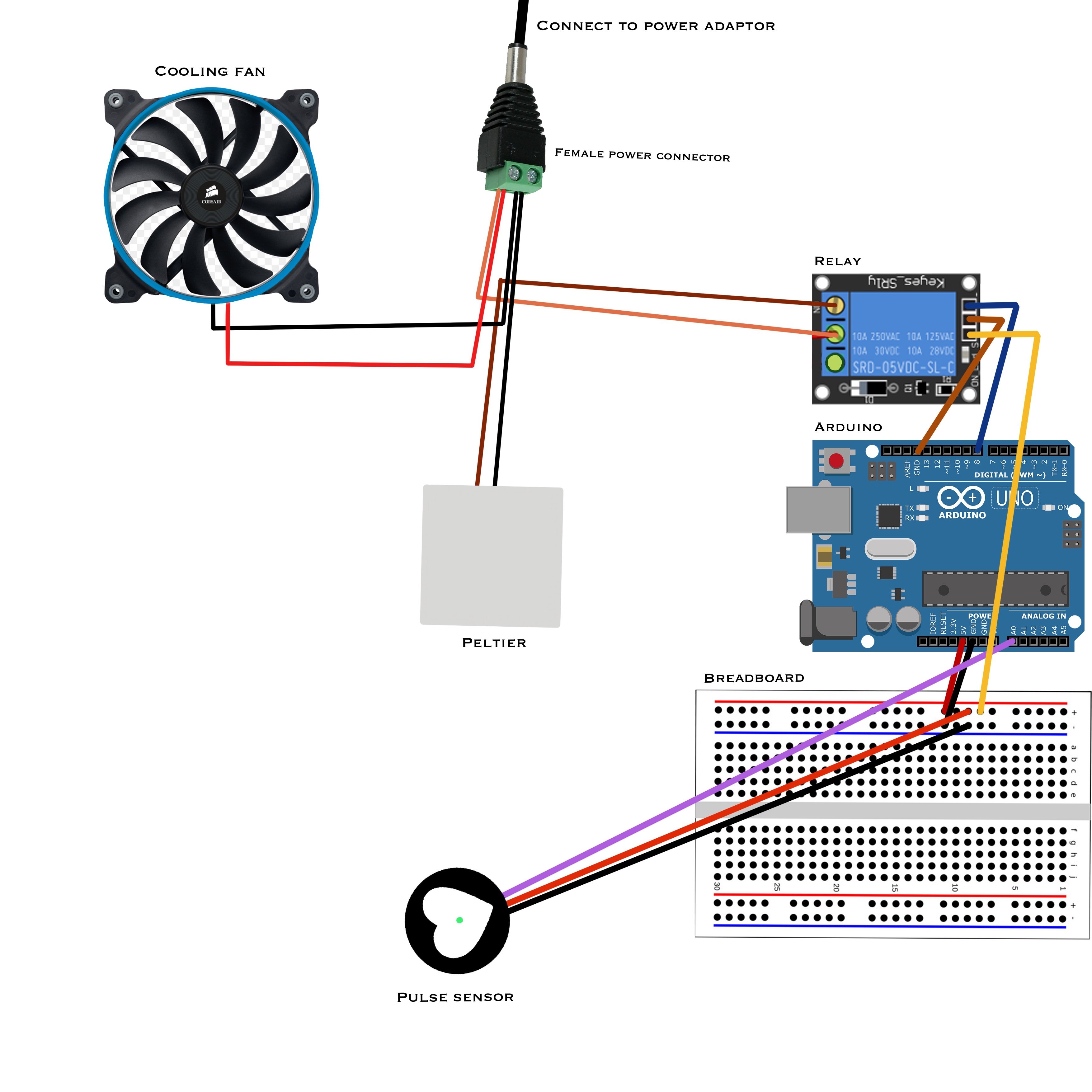
- Connect power and ground sources from arduino to breadboard
- Connect pulse sensor to breadboard and arduino
- Purple wire: any analog pin
- Black wire: ground rail (blue)
- Red wire: power rail (red)
- Connect relay to breadboard and arduino
- IN: any digital pin
- GND: ground rail (blue)
- VCC: power rail (red)
- In each slot within the female power adaptor, attach 2 positive and 2 negative wires.
- Connect relay to female power connector and Peltier (from top view – screws are at the top)
- Left-hand outlet: insert positive Peltier wire
- Middle outlet: insert positive female power connector wire
- Connect negative wire of Peltier and female power connector together using crocodile clips
- Connect female power connector to power adaptor
- Using the other set of positive and negative wires on the female power adaptor, attach the fan to the circuit.
- Paste Peltier module on top of heat sink and cooling fan at the bottom.
- Encase the Peltier, heat sink and cooling fan with an outer casing (in our case we used acrylic)
- Line the wires along the stethoscope and cover it up with tape/ tubing
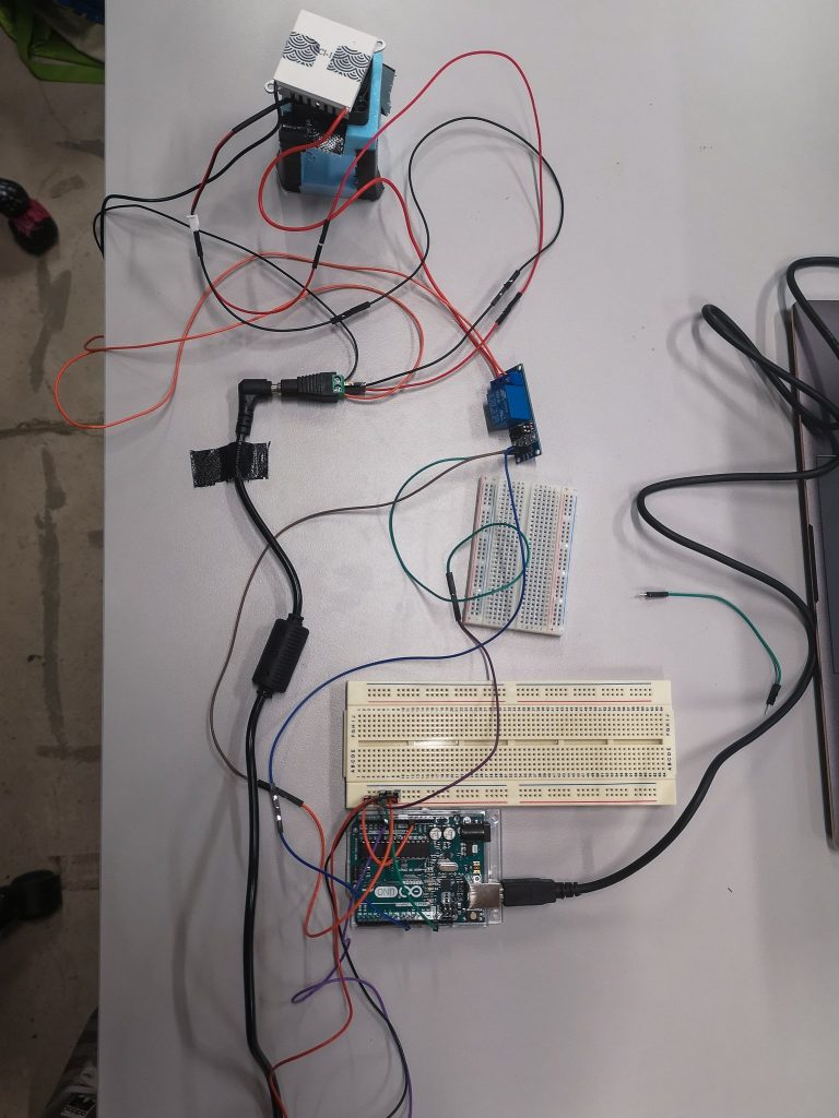
Codes and circuit design
Circuit design
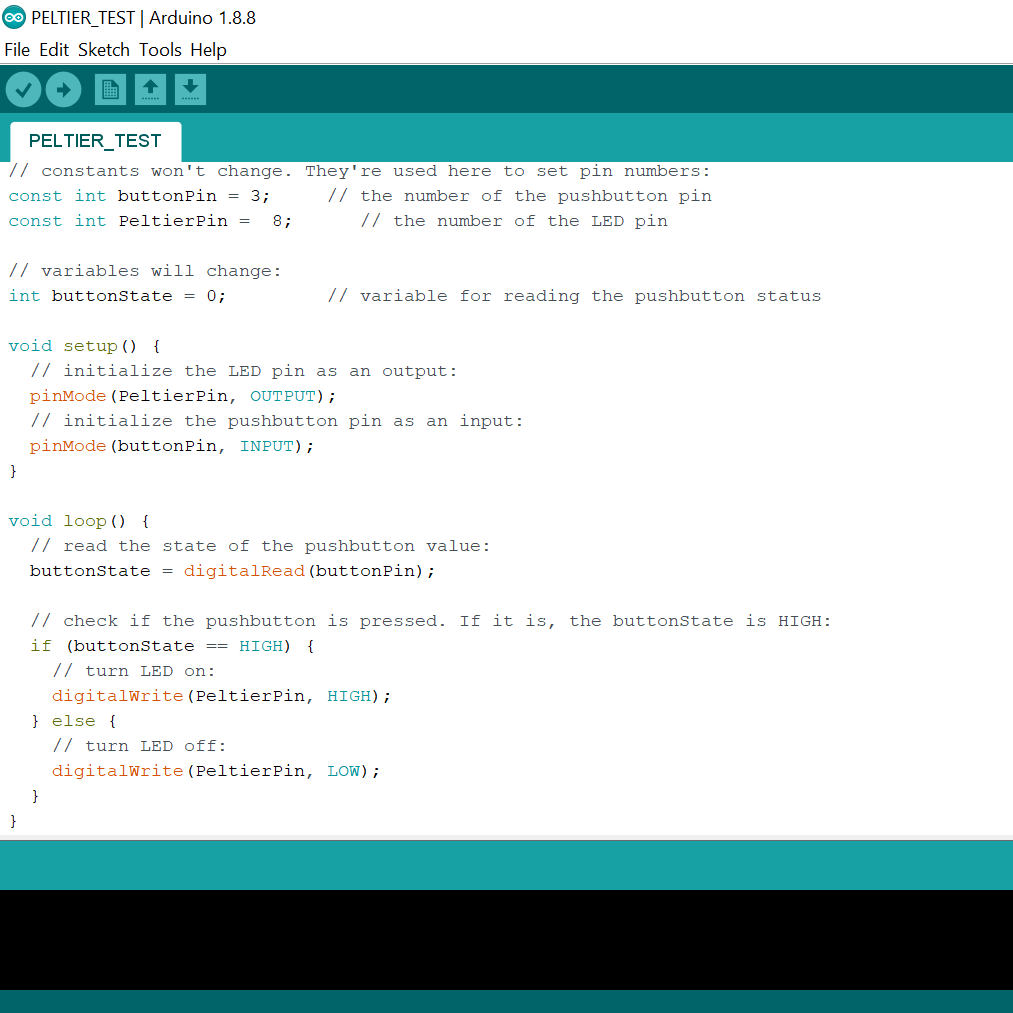
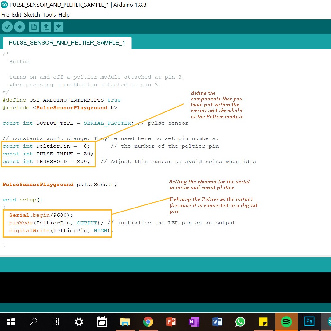
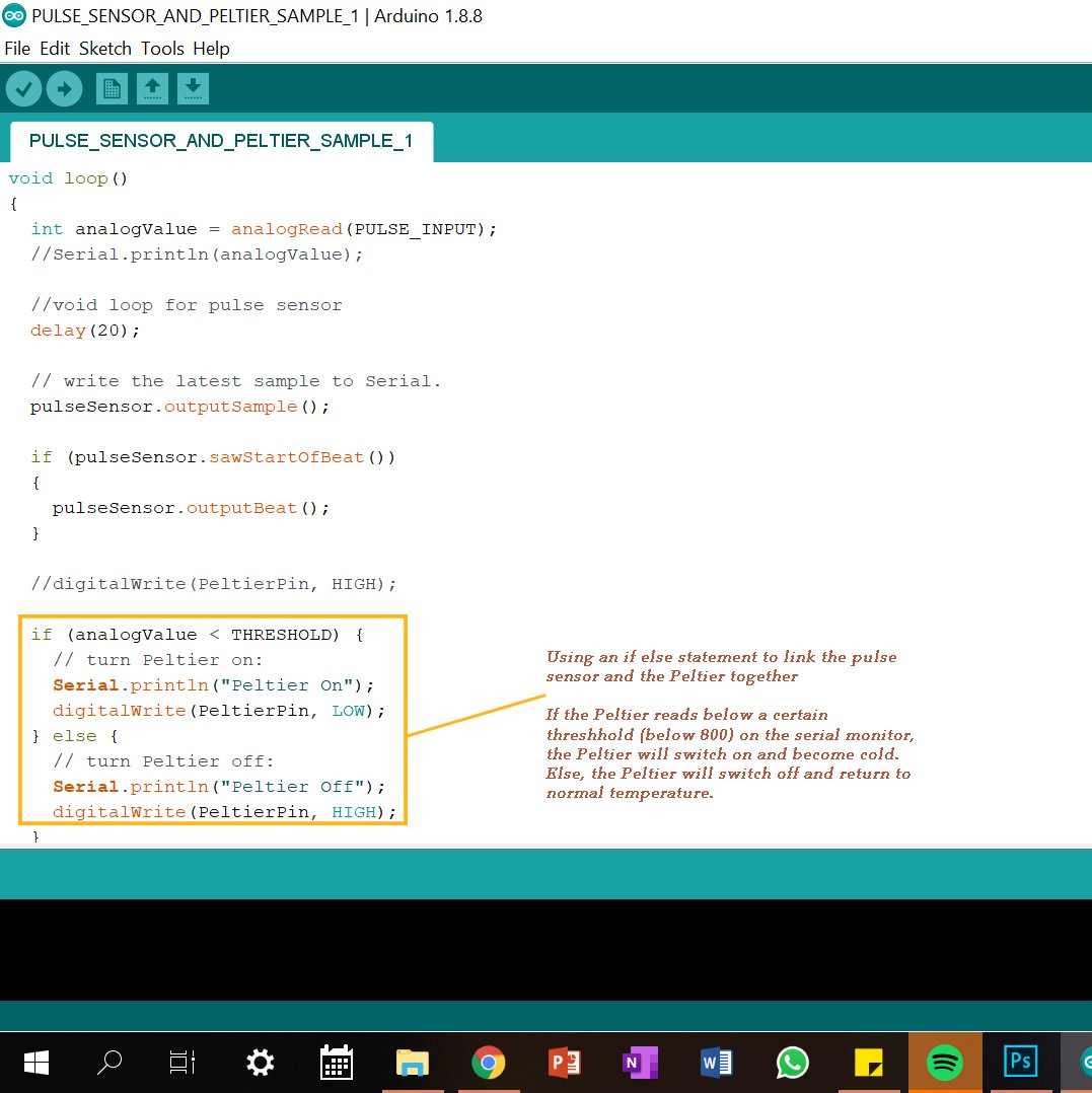
Codes
Issues and troubleshooting
We had many issues regarding the sensitivity of the Peltier module and the pulse sensor. Initially, the Peltier became very hot in a short span of time, when it was supposed to stay cold throughout the duration when the circuit was closed. Also it was only able to work once, and last for about 1 minute. We then realised that the heat sink and the cooling fan was too small to dissipate the heat produced fast enough, thus, we changed both of these components to bigger and thicker ones. That solved our issue about the heat dissipation. The one issue we could not really solve was the pulse sensor. Because the pulse sensor is partly a photocell, it senses light to activate the Peltier and has a threshold. However, the sensitivity of the pulse sensor is extremely high, and it triggers the Peltier to turn on and off at very high frequencies, and the Peltier module cannot keep up with it. We managed to find a more controllable threshold at 800, but that limited its sensitivity to sense ones pulse all the time.