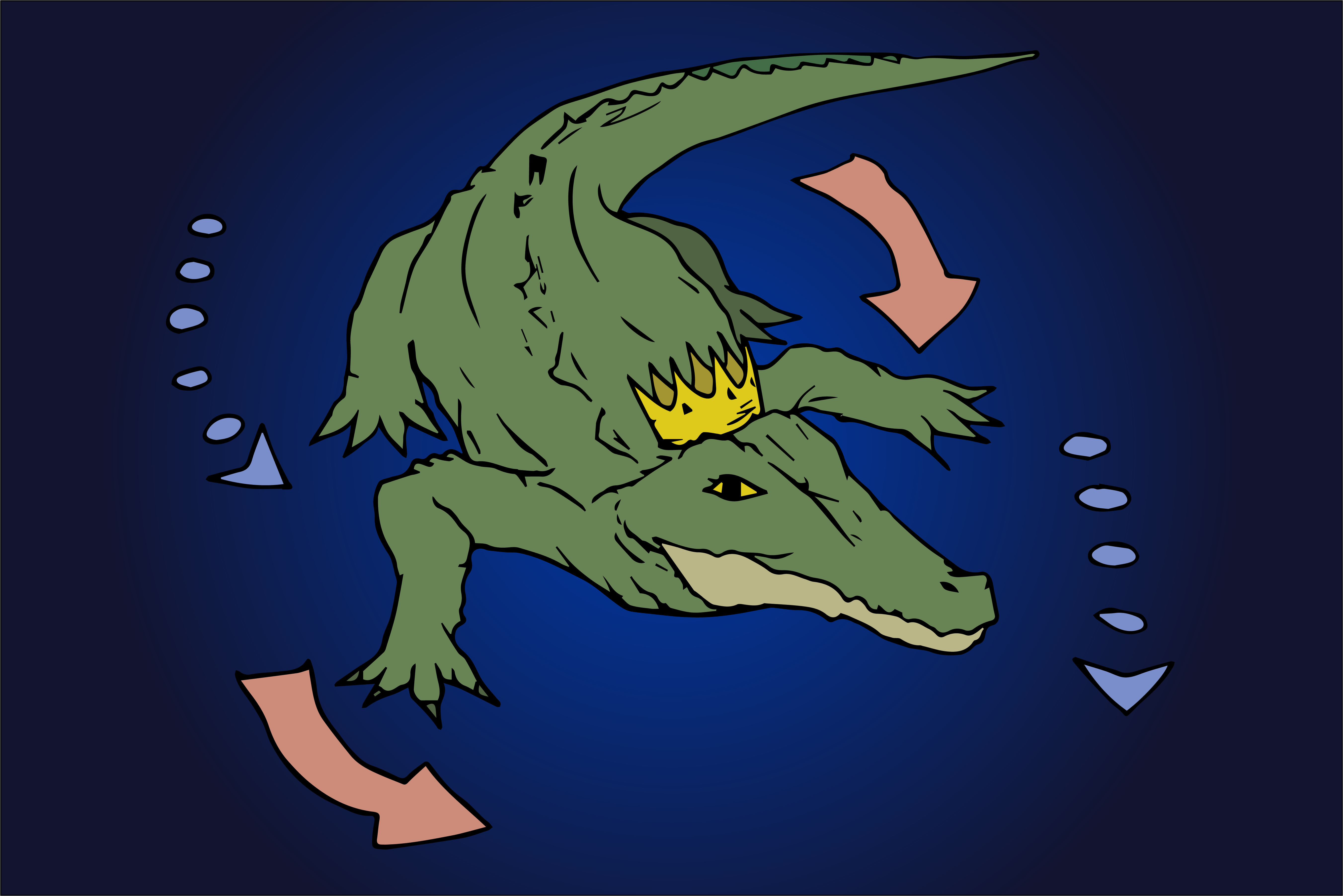
With the information we have from our research process, we attempt to create a model that moves in the eyes of the kinetic beast, much like Theo Jansen’s Strandbeests.
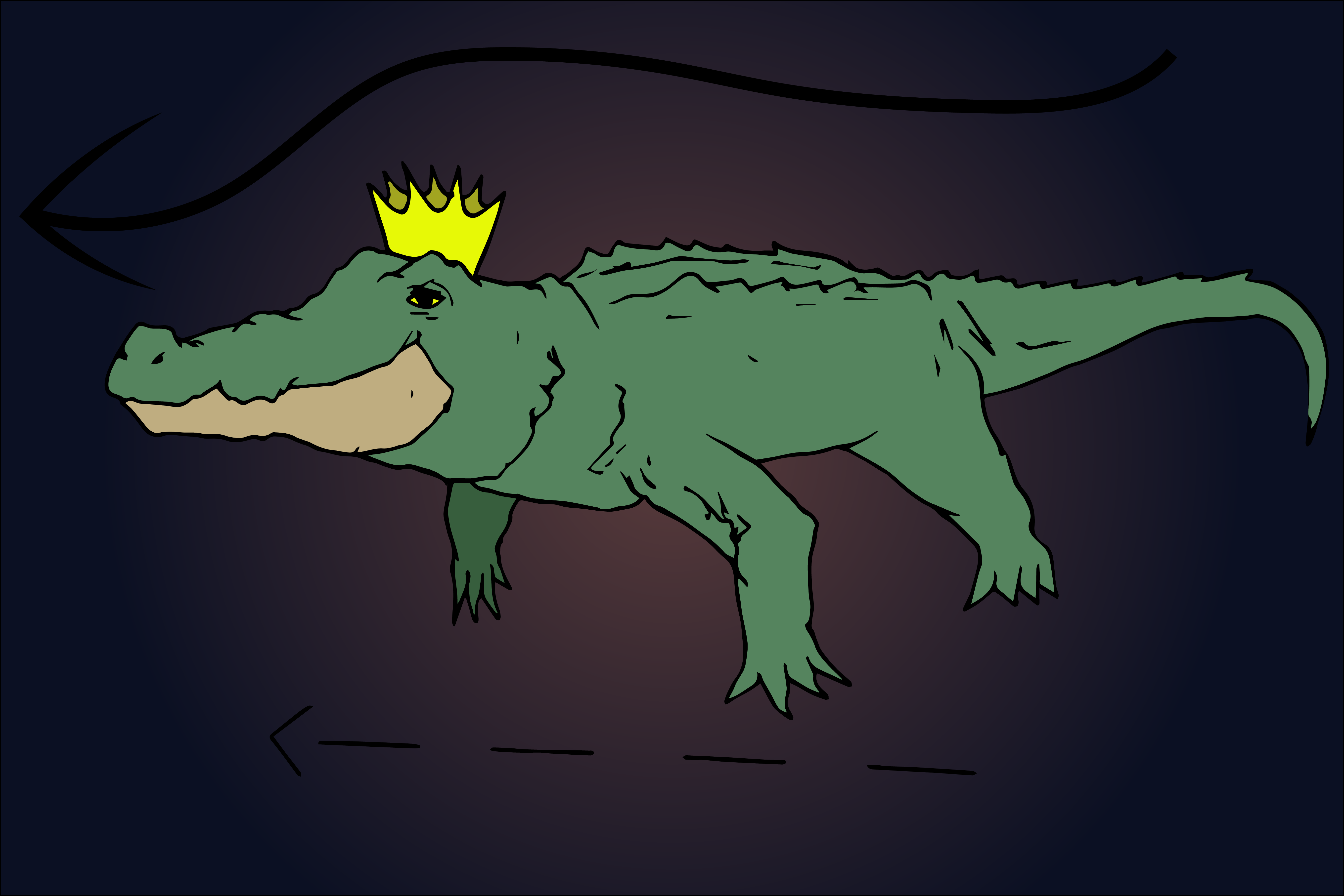
Breaking down the movements of a crocodile, I summarised it into two main movements: the slithering pattern inherent in its streamline bodyas well as the concurrent movement of opposite front leg and hind leg.
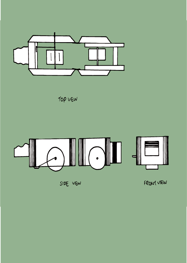
Refer to the diagram from the previous research process.
Slithering starts with floating in the middle of the water, then paddlingConcurrent movement of opposite legs
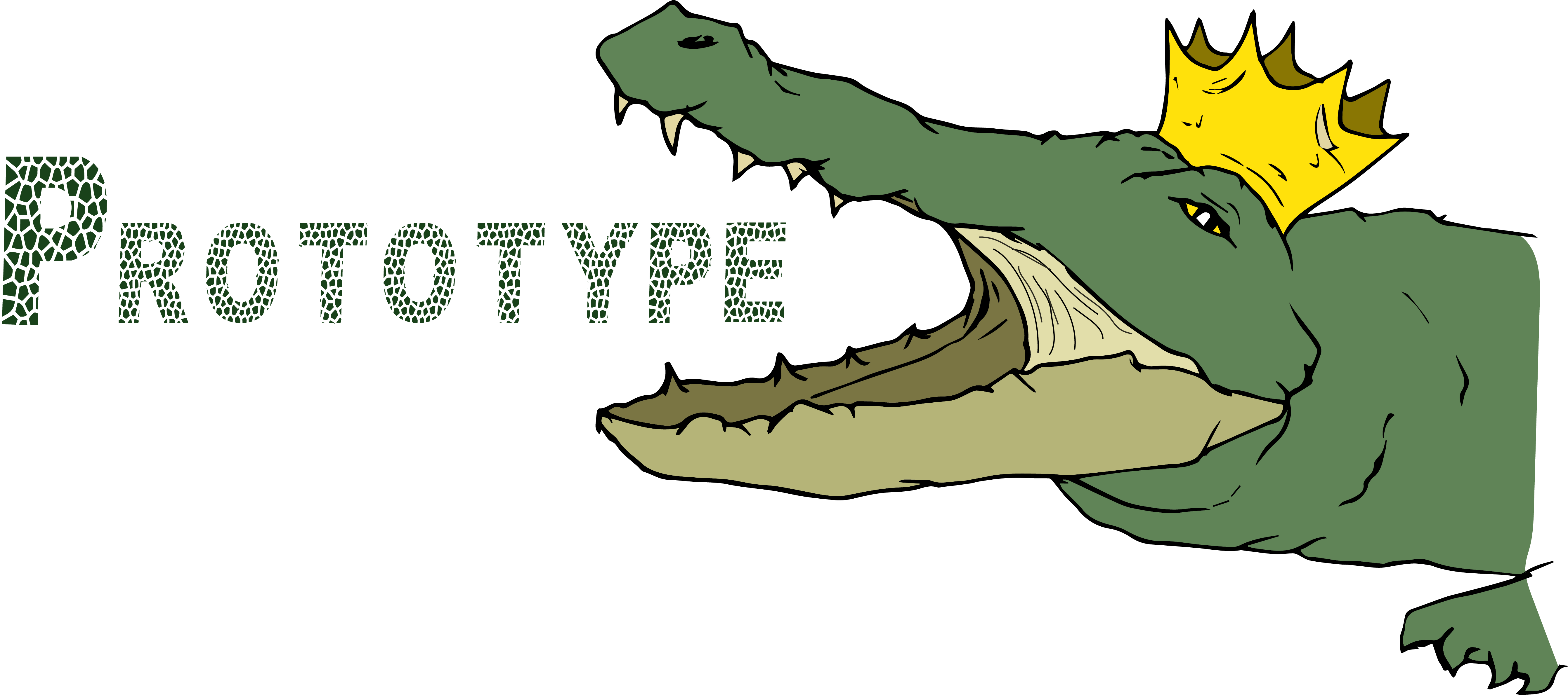
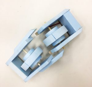
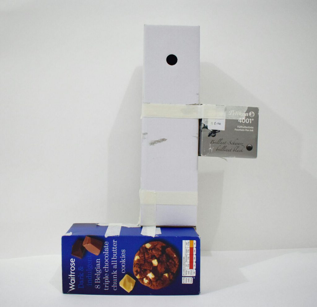
The first prototype attempts to investigate the slithering pattern inherent in a crocodile’s streamline body. This movement is only allowed with the flexibility of the pivotal mechanisms of the spine. Hence, I tried to apply it to the model by building it into two sections.
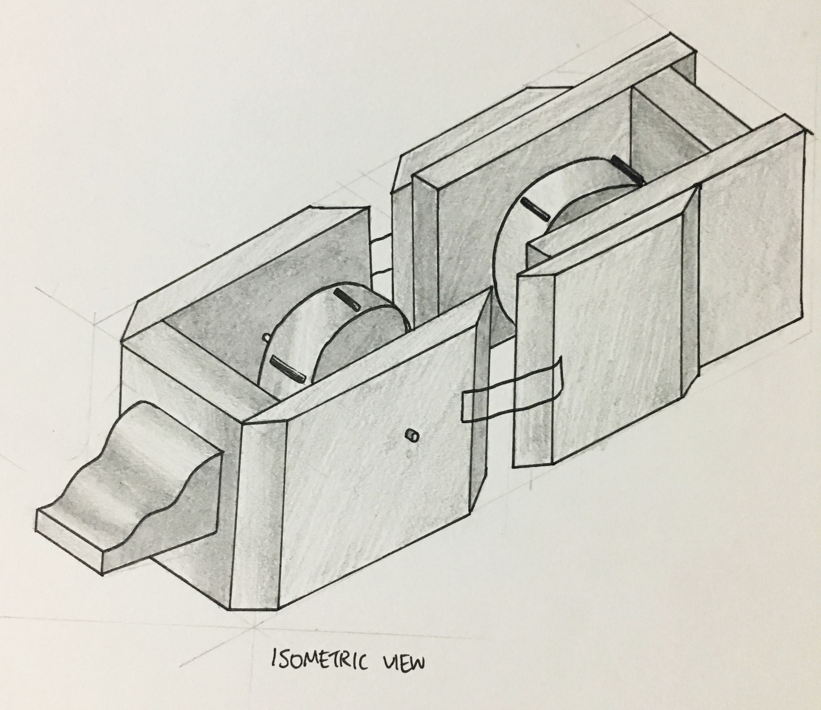
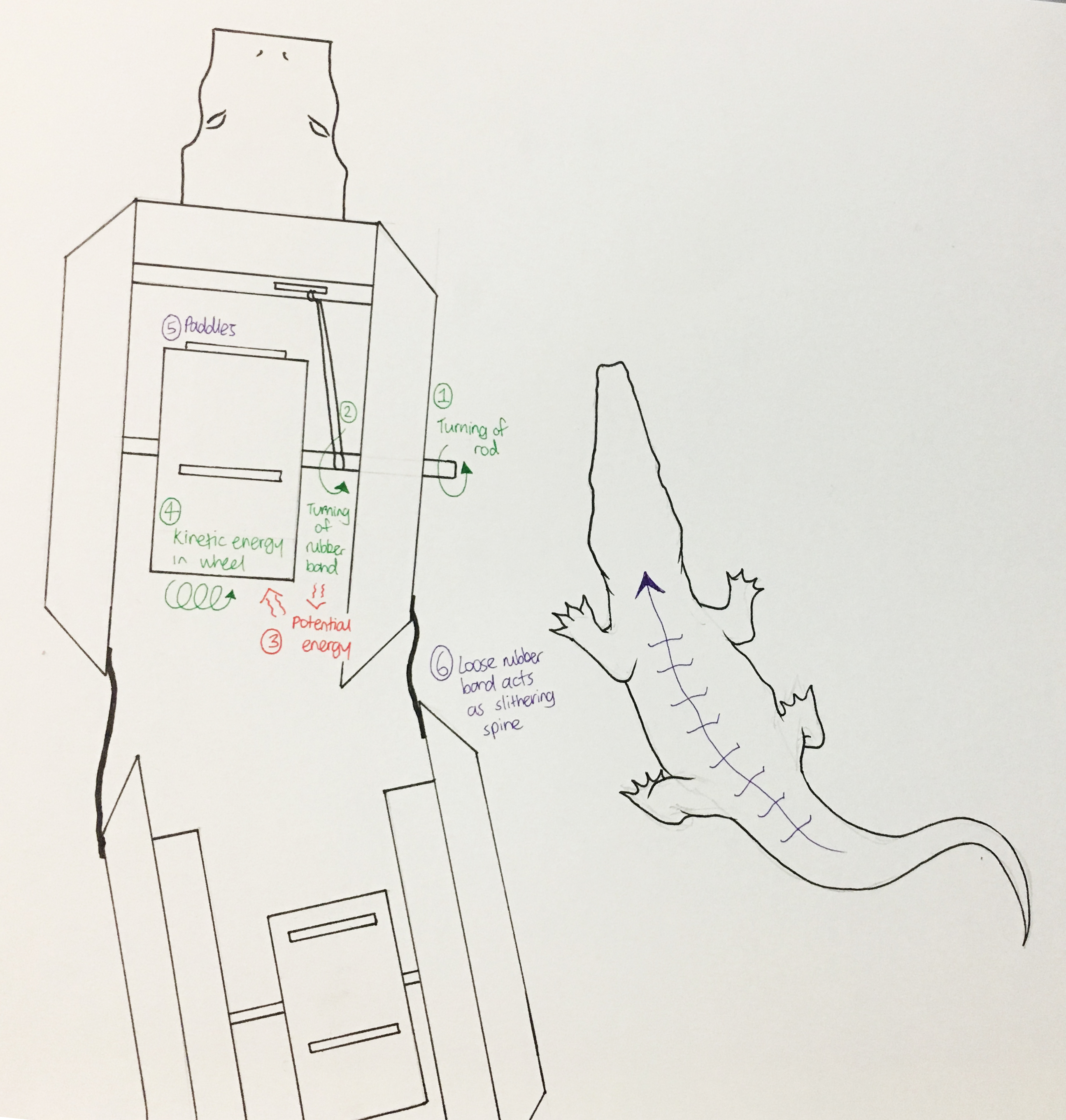
Isometric drawing of model
Mechanisms
Explaining the process of the machine, I used a wind-up mechanism to create movement. The rubber band is tied to the turnable rig that extends into the wheel. The rubber band is tied tightly onto the rig as well. Hence, when the rubber band is turned by the rig, it converts the kinetic energy of the spin into potential energy stored in the elastic band, shown in the diagram above. When released, the prototype mimics a wind up toy or pull back motor, and moves forward with the rubber band’s potential energy released as kinetic energy. The movement forward is enhanced with the paddles inserted into the wheel of the prototype. The loose spine connecting the two sections help to create the slithering movement of a crocodile.
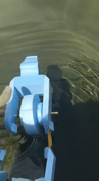
Test drive
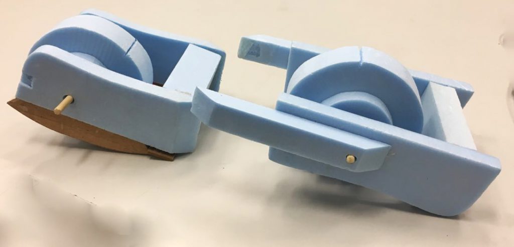
The prototype did not work well as the foam was too light. This made the prototype float above the water, resulting in a weaker albeit moving motor. The prototype only moved a short distance and did not slither as much as I envisioned. I added wood panels to the bottom in later adjustments.
I realised that the current equipment I have set up for the wind up mechanism is too weak, despite trying out different rubber bands of different elasticity. I tried latex rubber band, generic red rubber bands and hair band as well. Hence, I decided to change up into something else, and maybe work on the second movement- concurrent movement of opposite front leg and hind leg.
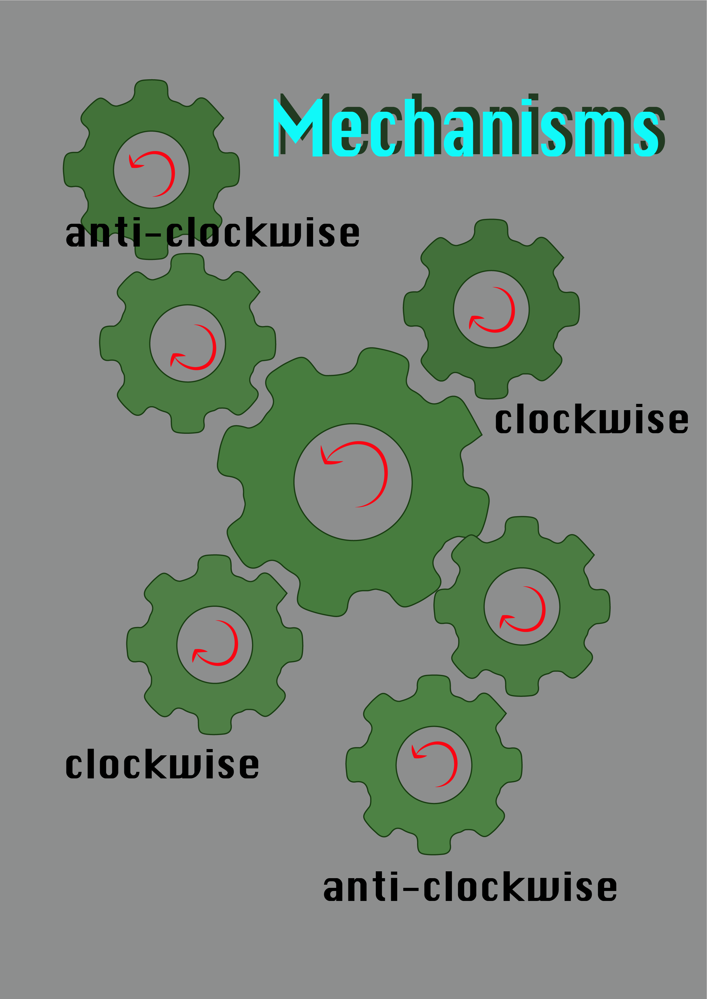
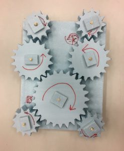
With the set-up above, I utilised gears to create different directions of movement. With the central gear acting as the main source of movement, it creates different direction between the top left leg- hind right leg and the top right leg-hind left leg. This concurrent movement of gears mimics how a real crocodile moves. This set-up would be useful if its morphed with the first prototype’s streamline shape, using either elastic band or wind energy to power the motor.
In the end, I was sick and didn’t attend class. However, Minjee did update me on the feedbacks given by Cheryl. Hence, we listed the characteristics down and planned how our final work would encompass, which are: Bobbing up and down the water like a crocodile, pecking of the plover bird and changing of colours with the temperature. Do take a look at Minjee’s OSS for the understanding of her plover bird prototype, in comparison for the mutualism relationship it shares with a crocodile.
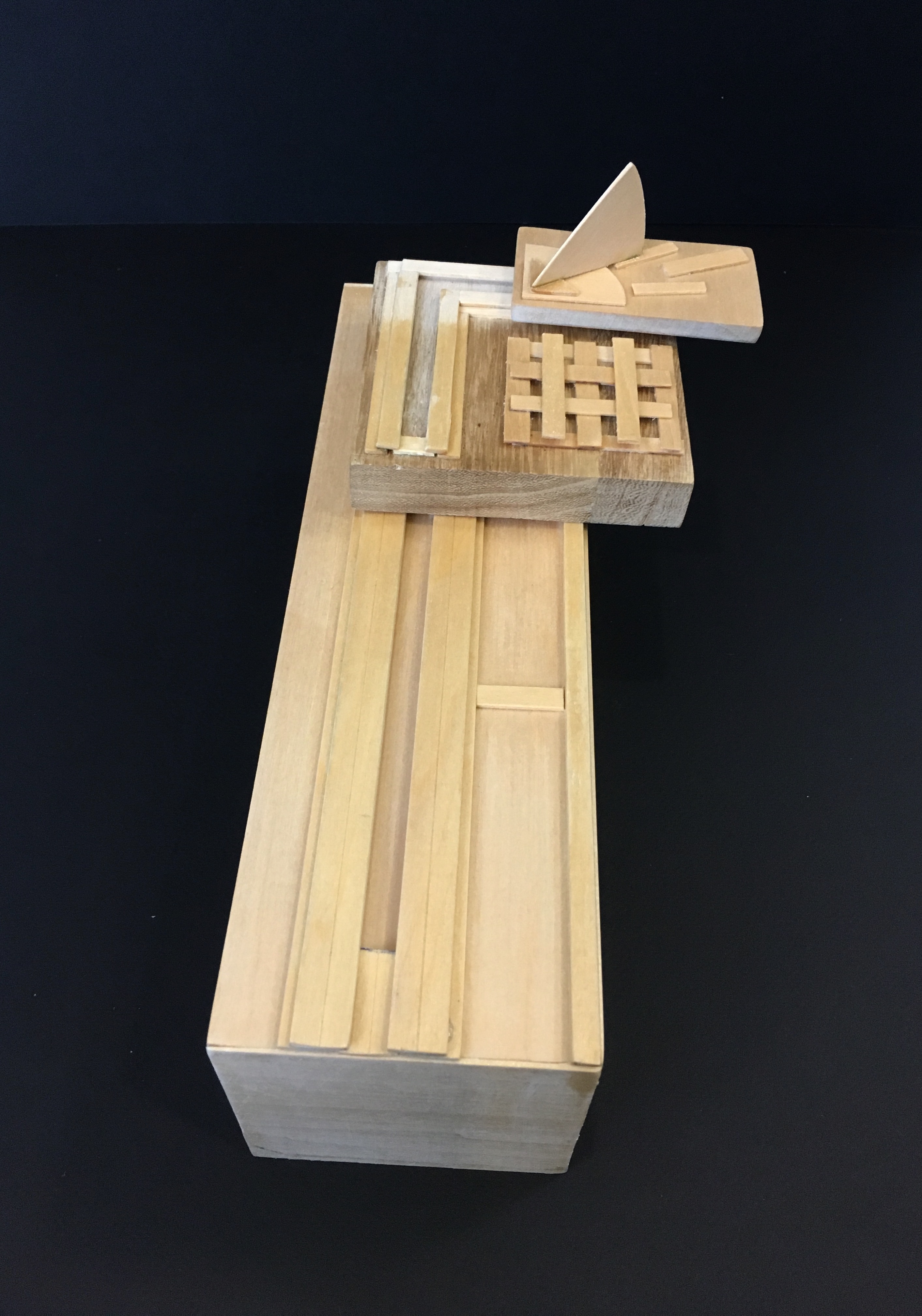
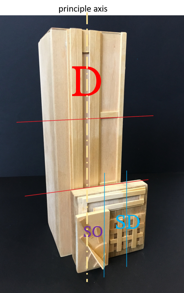
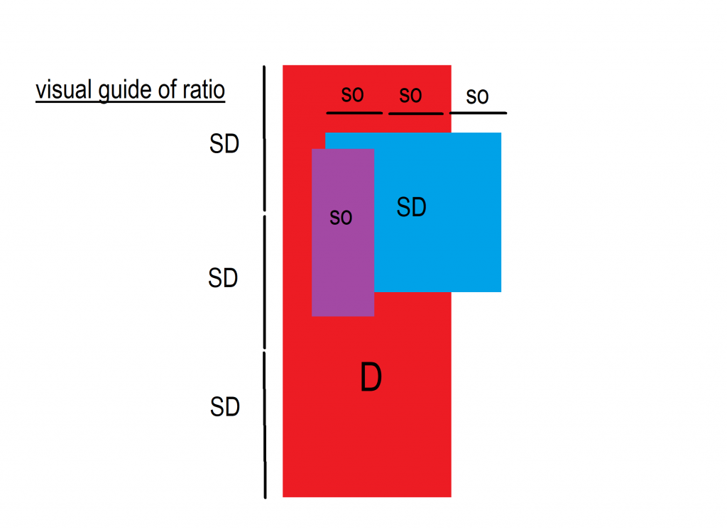
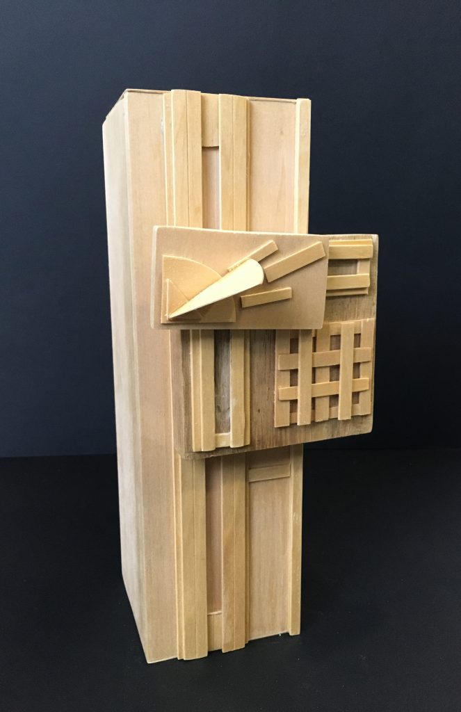
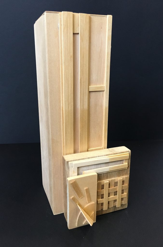
In conceptualizing the theme of “Rules of Third”, I have decided to play on the idea of 3 times 3 times 3. The above photograph was an initial attempt without the idea of 3x3x3. (link as shown above) The diagram below shows the prototype, after altering the size of the subdominant and subordinate blocks labelled SD and SO, reaching the ratio of 3:3:3.
The concept is to guide the eyes of the audience to conveniently and efficiently “perceive” the rules of third, through the visual ratios
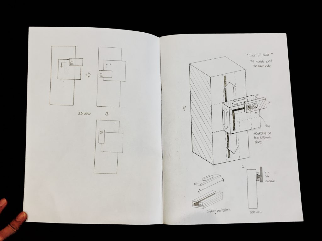
The sketch below highlights the process of constructing the model, where i experimented with different positions of placing the blocks. This was a difficult decision as there were many positions where the rules of third intersected- this was when i thought of the idea of motion. The motion of the blocks allow it to be moved along the imaginary line of third, allowing the audience to place it anywhere they like, or anywhere they deem aesthetically balanced. The added notion of motion adds a higher element to the sculpture, giving the sculpture a dynamic appearance and appeal.
Preparatory Sketches
Movement
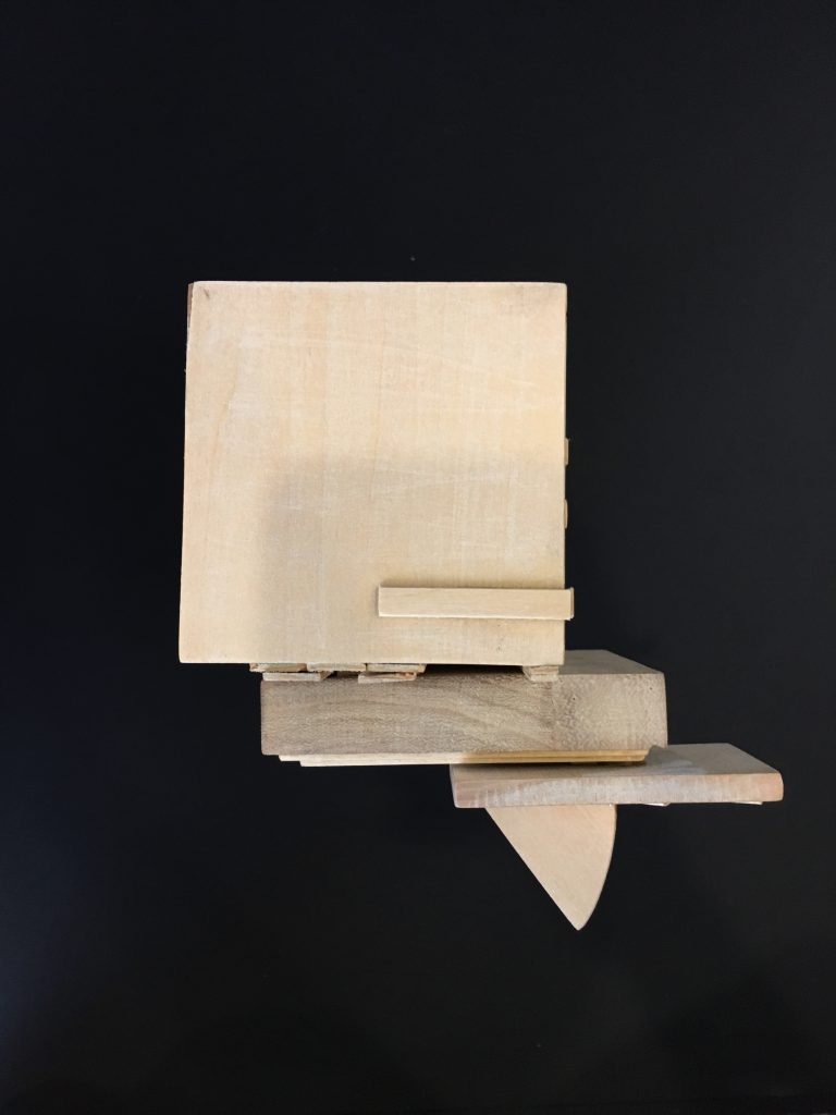
Shown in the above diagram, I drew out different ideas of movement, and ultimately went with the above settings. The selection was based on the functionality of the sculpture, which would be a fun fair ride that moves in all direction. The diagram is a series of 2D sketches that highlights the different movement the sculpture is capable of, a series of photographs and GIFS will be provided below for more visual aid.
GIF 1. SO block rotating at one point GIF 2. SO moving on SDGIF 3. SD moving up and down along D
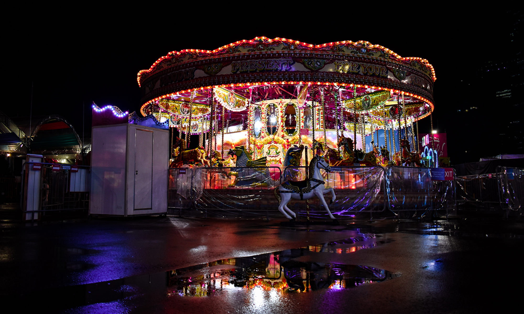
I have chosen the functionality of a fun fair ride as I found the movement of the blocks along each other to be intriguing. The concept of movement on movement is unique and it would be difficult to locate an effective function, other than a fun fair ride, like the Double Shot Ride in Georgia, Wild Adventures. This functionality is also effective in using all three blocks in different ways, the SO being the 360 degrees rotating/ moving seat, the SD being the main block that moves up and down, while the D being the main sturdy block that holds everything together
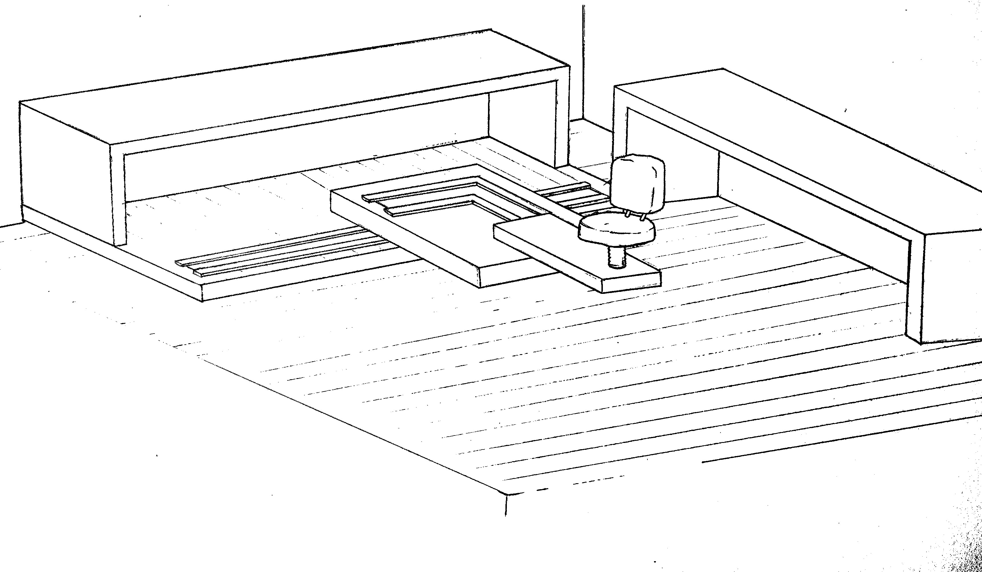
I have chosen to use wood in creating this design as wood is sturdy and reliable, especially in creating architectural designs like buildings and hard structures, such as my final product. Wood can be easily manipulated and put together, especially in creating the movement I intent to create. Shown in the bottom right side of the sketch, I have a rough design of how to enable the movement of the blocks, using the sliding mechanisms of the T-structure of the blocks.
In the process of creating this product, the problem that I encountered was the added movement of rotation of the SO on SD, shown in GIF 1. It was only resolved through the usage of a smaller T-shaped structure within the hook, shown by the sketch shown above. I also enlarged the perpendicular corner of two interacting hooks, allowing the T-Shape structure of the SO to rotate around freely.
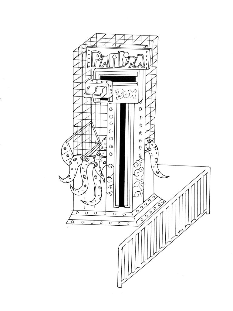
Also, the variety of material used in this model is limited to wood. This is due to an attempt of achieving an unified look. However, in any situation where there is a need to recreate a prototype of the fun fair ride, etc, I would explore a larger variety of materials, shown below in the sketch model of the Pandora’s Box funfair ride, mainly metal and wood.
Sketch of Funfair Ride
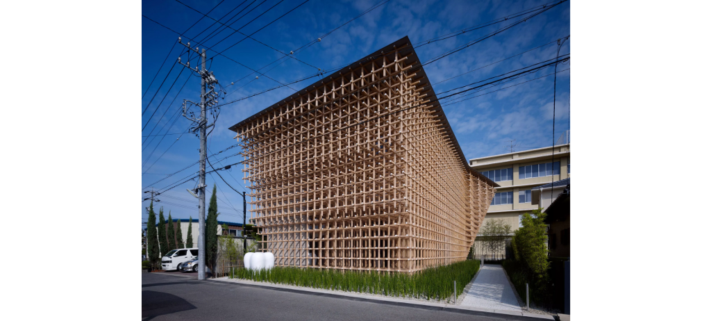
An artist reference I have under this assignment would be Kengo Kuma, Japanese architect. I found his works to be interesting due to the spatial quality created by the criss cross of wooden planks, especially in the design of the Prostho Musuem Research Centre in Kasugai Japan. I found the criss cross to amplify the negative space within the building, creating an almighty effect. Hence, I decided to decorate the final model with criss cross wooden pieces to pay tribute to Kengo Kuma’s works. In my sketch design for my fun fair ride, I decided to eliminate the criss cross wooden plank and use metal wiring instead due to the practicality of the object. The metal cage would be sustainable due to its location being outdoors and susceptible to rain and wind. The decorative nature of the final model would be a pointer to look out for.
GC Prostho Museum Centre, Kengo Kuma
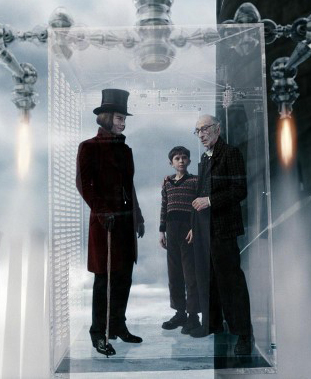
An interesting point raised up by Cheryl was how the model parallels to the Glass Elevator in Willy Wonka’s factory. The link provided below shows a video highlighting the extend to which the Glass Elevator can move, much like how I envision my model to be. An interesting point to note would be the usage of glass as a material for the model, bringing to life a fantastical theme, a tribute to Charlie and the Chocolate Factory as a cult classic. This would be a great link especially for the main functionality as a fun fair ride.
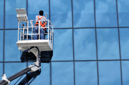
Another function that this product is capable of would be a tool for cleaning tall buildings. With the rotating and moving mechanics mentioned above, cleaners would be able to clean the windows of tall buildings with convenience, moving side by side, as well as reaching different corners- solving the issues of right-left hand inconveniences. The problem with this functionality would be the inconvenience of moving such a big structure. However, to resolve this issue, adding wheels to the base would allow the user to move the structure around freely, like a Forklift Machine.
Another function that I had came up was an idea created when I laid the model horizontal. The function of the model moving at all direction, with the SO being able to touch every corner of the model, allowed me to idealize the Convenient Chair. The SO being the chair will allow the user to move to any corner of the room without moving. The intentions of this product is to create a convenient environment of work for paraplegic users, such that movement to grab items or getting more space for office work is much more convenient, as the name suggests. The user just has to use a remote to access the direction at which they want the chair to move, be it the left side corner of the room or the opposite end; the usage of two rectilinear planes inter-moving will allow an extensive access to a wide direction of space.
The Convenient Chair can also be an upgrade and used in various forms. With its horizontal plane, it could be used for filming, the ability to capture vantage points from various angles.

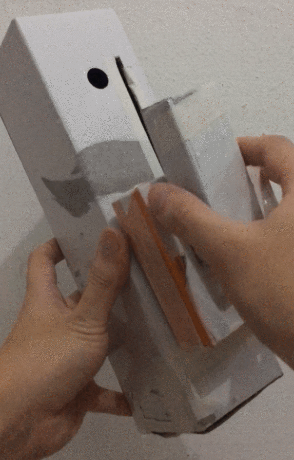
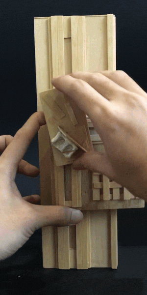 GIF 1. SO block rotating at one point
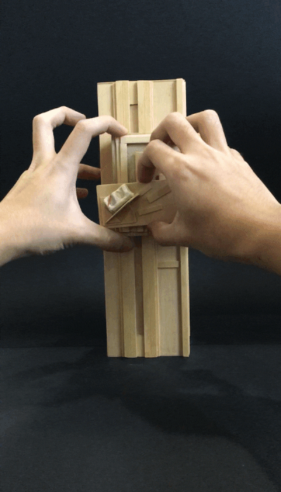 GIF 2. SO moving on SD
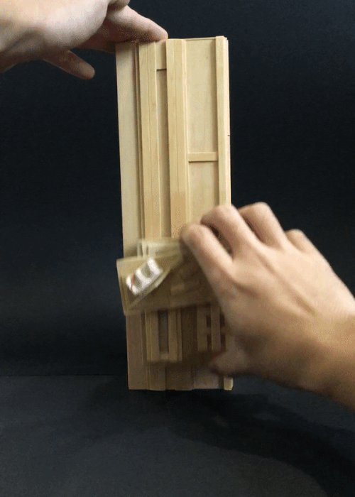 GIF 3. SD moving up and down along D
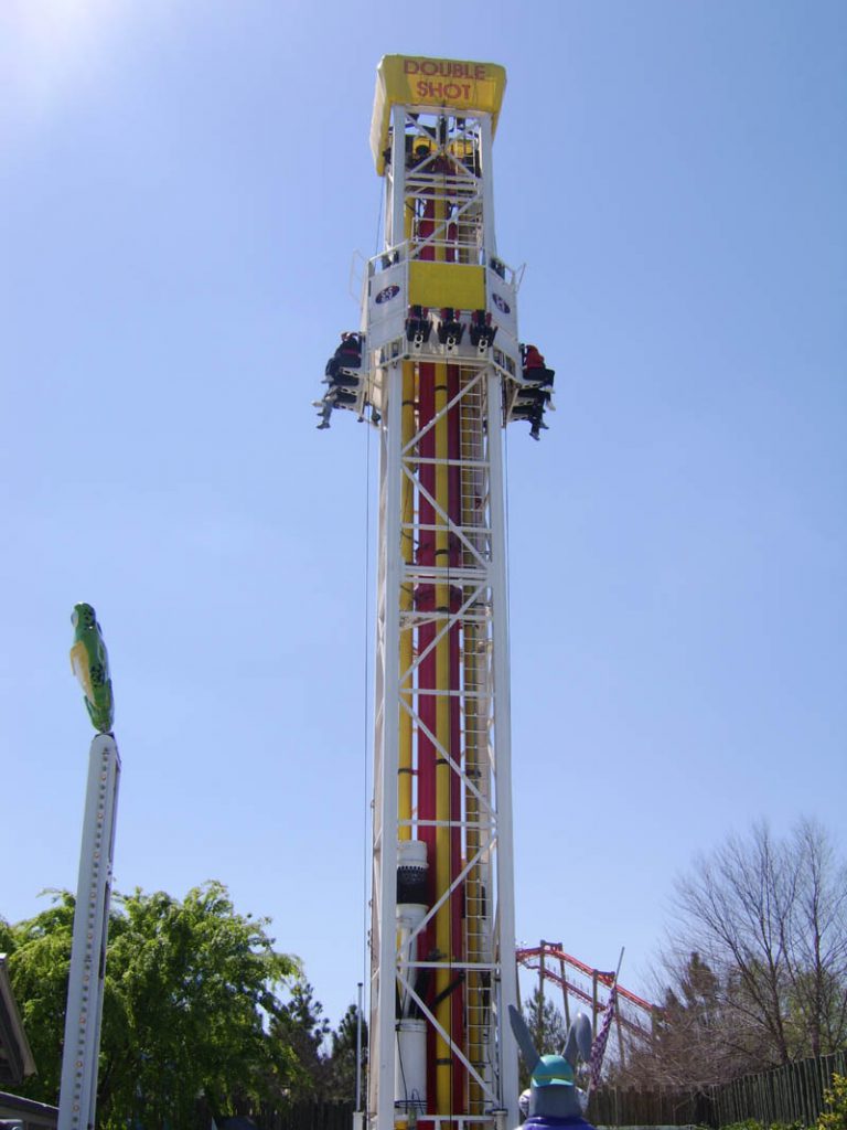

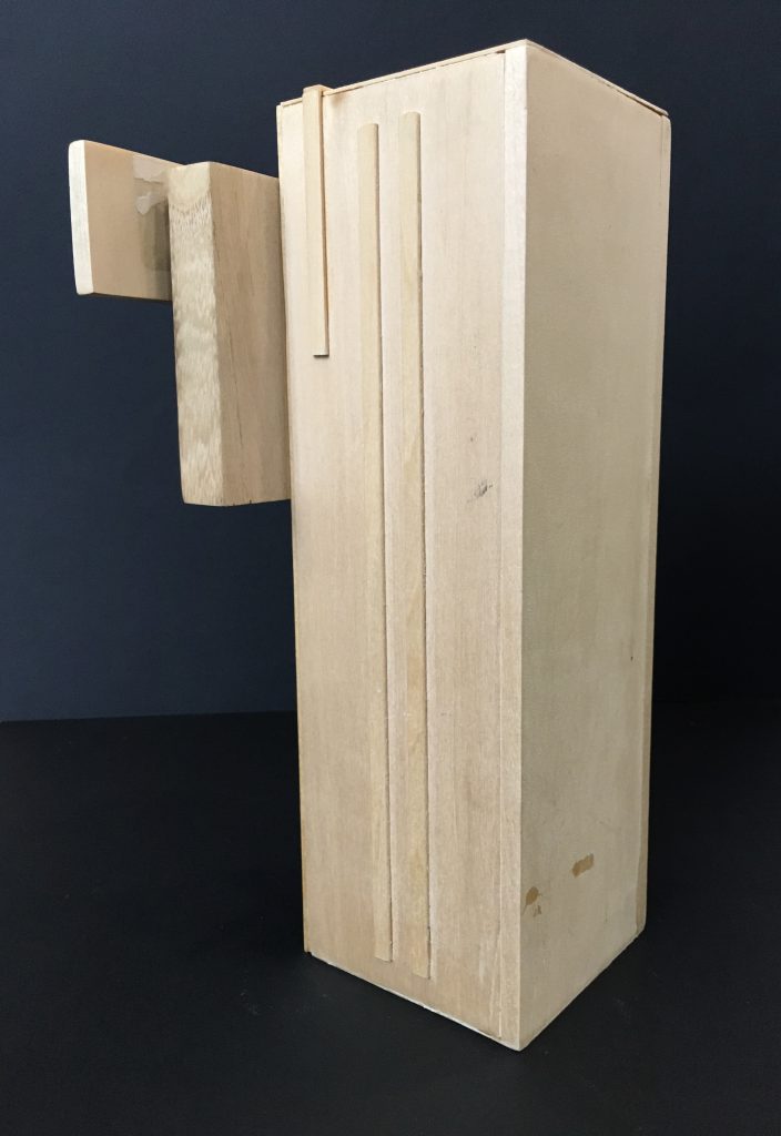 Side View
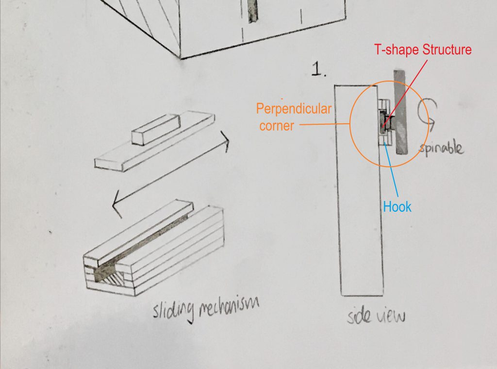 Close up on Sketch