Sketch Model 1
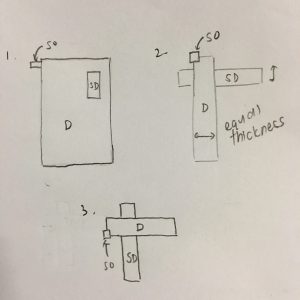
The first sketch model was the one my final model was mostly based off of. In this model I attempted both the wedging and piercing techniques, by piercing the SD piece through the D and wedging the SO into the D.
As seen from figure 2, the D and SD were of almost equal thickness, due to having been cut out from the same piece of foam. Hence in the final model I re-cut the D from a thicker piece of foam.
Sketch Model 2
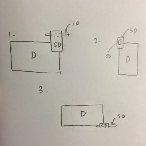
My final model was also partly based off this sketch model, as I wanted to attempt a model where the SO is placed on the SD rather then the D. In this model, I also attempted both piercing and wedging but applied it in different ways. The dotted line in figure 1 shows where the SO was pierced into the SD, while the SD was then wedged into the D.
This model is flawed as the SO is too long, hence from some views such as the one in figure 3, it appears longer than the SD which causes some confusion. While I attempted to avoid this confusion by making the SO 1/3 the thickness of the SD, it was still significantly longer as it had to be pierced into the SD. Learning from this experience, in my final model I chose to wedge the SO into the SD rather than piercing it so that I would be able to use a SO that was less significant than the SD from all angles.
Sketch Model 3
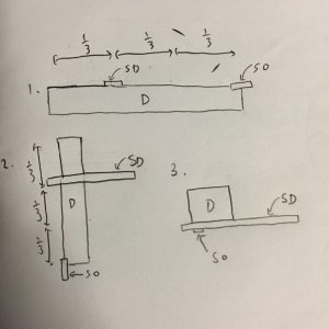
This model was least like the final model as I preferred to work with a D that was more block-like and not as long as this one. In this model, only wedging technique was used.
This model was not viable as you can see from figure 1, where the SD appears to be much smaller than the SO. This is because while the SD was a longer piece, it was also very narrow and its width corresponded with the length of the SO. Furthermore, in figure 3, the SO is only very barely visible due to being wedged too far into the D. Hence from that angle it might not be readily apparently to a viewer that there is a SO piece.
Nevertheless, the model is not without merits. Figures 1 and 2 show that the placement of the SD is such that it is placed exactly 1/3 down the D, giving it more visual coherence.
Conclusion
While all models have their pros and cons, ultimately the model I favoured most and chose to base the final model off is Sketch Model 1. This is due to the flaws in models 2 and 3 which I had stated above, but also because it was the only model which had D, SD and SO facing 3 different axes (x, y and z) which makes it visually the most coherent of the 3 models.
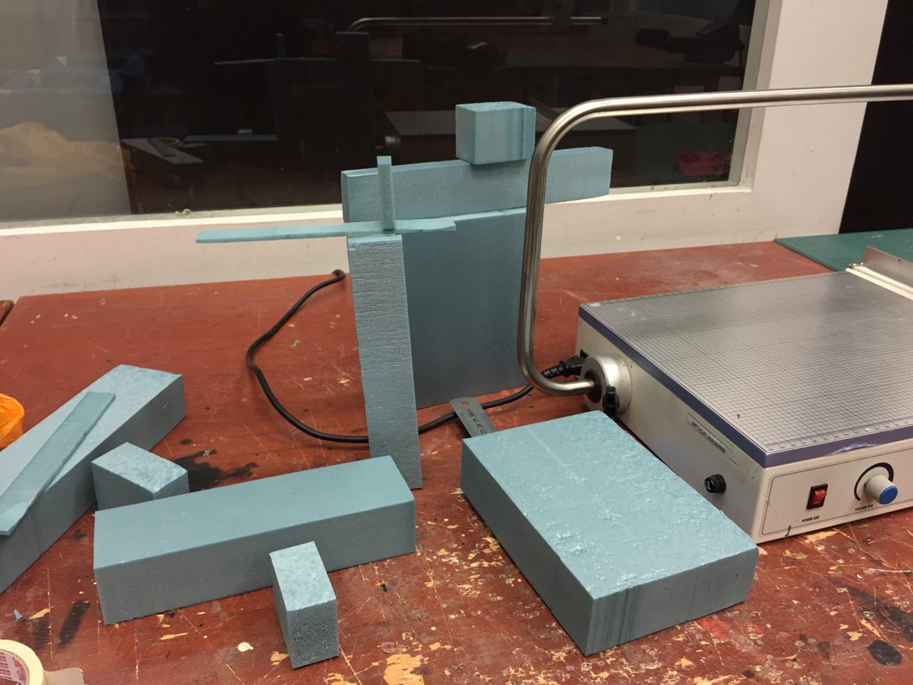
Remember to photograph each of your 3D Sketch Models from different viewpoints in future Bridgel. If the 2D sketches you posted are of the original 3D Sketch Models, then you needed to show the 2D Sketch Analysis with the intended improvements to be made (eg: what to add, what to subtract). The constant to and fro between 3D Foam Model and 2D Sketch Analysis is essential before arriving at the Final Model. This exercise trains an objective and critical eye for 3D composition. It is rare and near impossible that anyone can come up with a ‘ONE HIT WONDER’ on their first 3D Sketch Model.