With the all-new Technicolor View-O-Matic, you too can view a bitcrushed camera feed of your surroundings in glorious 32-bit color.

The Technicolor View-O-Matic!
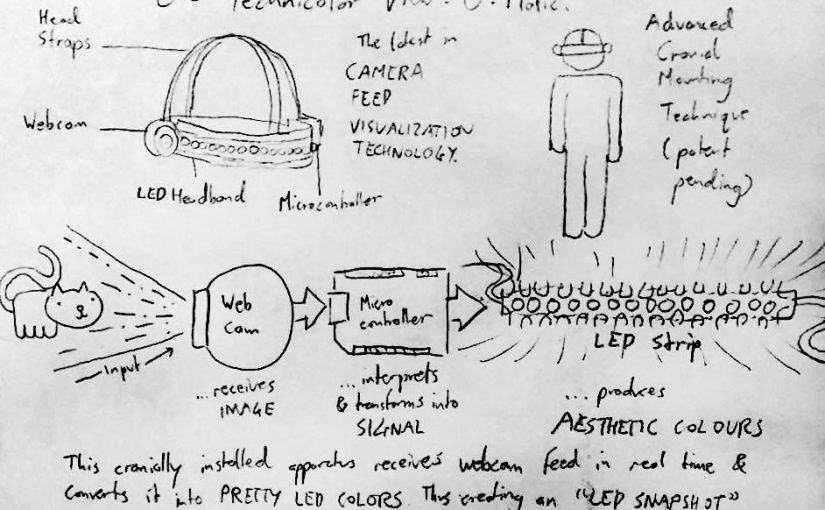
The latest in CAMERA FEED VISUALIZATION TECHNOLOGY.
Head Straps – Webcam – LED Headband – Microcontroller
Advanced Cranial Mounting Technique (patent pending)
Input
–>Webcam …receives IMAGE
–> Microcontroller …interprets & transforms into SIGNAL
–> LED Strip …produces AESTHETIC COLORSThis cranially installed apparatus receives webcam feed in real time & converts it into PRETTY LED COLORS. Thus creating an “LED SNAPSHOT” of what the user is looking at. Or an “LED MIRROR” of their vision.
The premise of this assignment was to build something for an LED manufacturer’s showcase at a trade show. I’m a cheapskate who is allergic to expensive hardware, so I tried to make something with minimal components and using only those items that I could borrow.
As you can see, the original concept for this device included a headband but the video log does not. I was unable to get the LED strip to stay attached to the elastic headband without modifying either the headband or the LED strip. In the end, I figured it was better to have a working prototype that wasn’t wearable, rather than risk damaging the school property I borrowed.
The way the device is put together is very simple. It’s really just a webcam linked to a computer (with Processing sketch) linked to an Arduino linked to an LED strip. The hard part was making the code happen.
Aesthetic Colors
I put some thought into how the webcam input would be translated into 33 LED signals. You see, the goal is not to accurately render the webcam visuals, but to translate it to lights in a way that looks cool and is visually interesting. To do this I had to start from visualizing the end product and work my way backwards.
First of all, I wanted to create a device that would visibly “pan” left to right as the camera was turned left and right, as can be seen in the video demonstration. This meant that the LED output had to be sensitive to the horizontal position of pixels in the camera feed. I accomplished this by making the Processing sketch sample 33 pixels along the midpoint of the camera feed, from left to right.
Second of all, I wanted the LED output to clearly be based on what the camera was looking at, but not necessary have any visual correspondence to it. I didn’t want the LED strip to just be the same color as the camera feed. To do this, instead of using the raw color data, I manipulated it to use the saturation data for the final hue and the brightness data for the final saturation. I also set the final brightness to always be maximum, because the LEDs wouldn’t be very eye-catching at a trade show if they were dimmed or off.
The final result of all this tinkering can be seen in the video presentation.