**To see the final PDF by Brendan and me click here
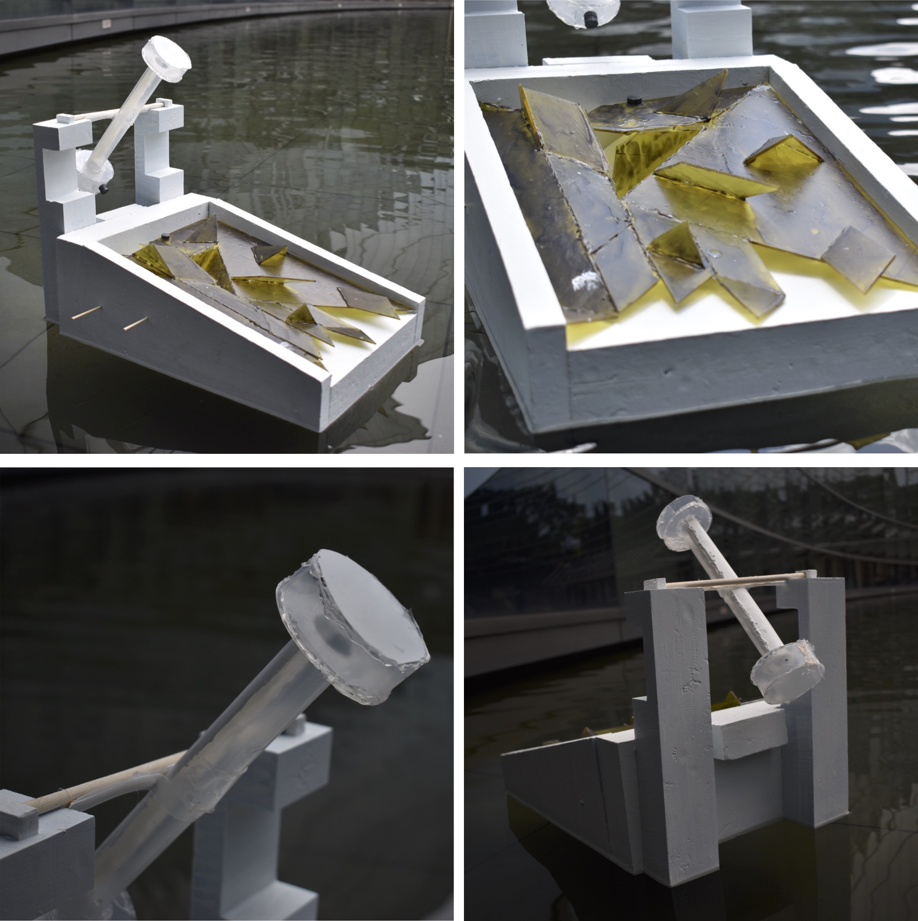
We had a lot of ideas for our crocodile and plover bird kinetic beast but not all of it worked out. So here are some of the explorations, challenges, and potential changes that could be made.
?Overview?
1. Pot pot boat (challenges & potential changes)
2. Magnet repulsion (challenges & potential changes)
3. Sails (challenges & potential changes)
4. Magnetic dam (challenges & potential changes)
5. Thermochromism
6. Additional explorations

 Our kinetic beast was able to float in the waters of ADM but we wanted more. What if it was able to propel itself forward on its own? Both crocodiles and birds are attracted heat so we decided to draw inspiration from a pot pot boat (also referred to as pop pop boat, popping boat, and etc) that uses heat to move forward.
In theory, a pot pot boat is a toy that uses a simple steam engine. The steam engine in this case is usually fueled a candle or vegetable oil burner. The engine of a pot pot boat consists of two parts. The boiler room and an exhaust tube that is connected to it. Heat is applied to the water, water in the boiler evaporates, steam is produced. The molecules of steam is more widespread than water and thus needs more space. So the expanding steam pushes out the water from the exhaust tube and propels the boat forward. A popping noise is made when this happens. This is where the pot pot boat gets its name.
In our case, we had a small flat candle warming up a metal plate fashioned out of an aluminum can. The metal plate, which is the boiler room, is connected to two straws. One straw will be sucking in water into the boiler room while the other is pumping out water. The water that is pumped out should move the kinetic beast forwards.
When we tested it out the boat was floating alright but did not move forwards. We were unable to hear a popping noise either. However, the candles were heating up the boiler room.
Potential changes can be not using exhaust tubes (the straws) that are too narrow and short to propel the whole boat. We could have used bigger ones. With a combination of bigger straws a bigger boiler room that could let out more steam at once, perhaps the boat could have moved. In addition, a bigger candle could have been used to heat up the boiler room more quickly. This will lead to more frequent pops as the steam is let out.


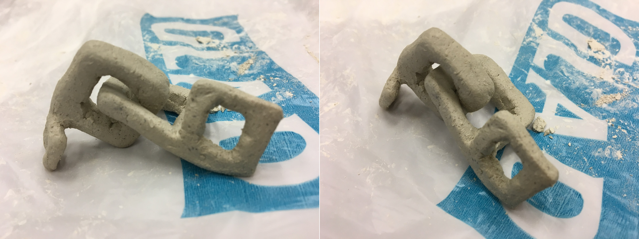
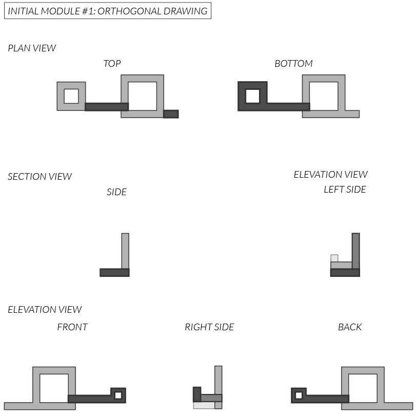
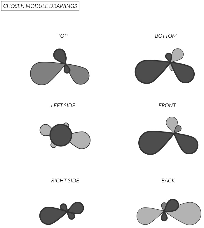
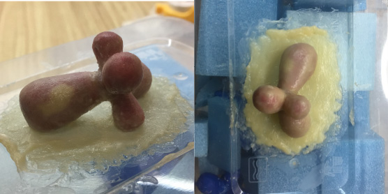
Our bird is the tube with two round circles on either end as shown in the photos and illustration above. It is supposed to oscillate up and down whenever water is poured into the tube and it pours out. To assist this process we decided to incorporate magnet repulsion.
In theory, there is two sides to a magnet. A part that repels and a part that attracts other magnets or metal pieces. We wanted the magnets secured on to the boat to repel the bird tube so it is always dithering.
In our case, we will be attaching small flat coin magnets on the edge of the tube. Another magnet will be attached the white boat body of the kinetic beast.
When we tested it out it worked out in one scenario and did not in the other. The scenario that worked out was when we were experimenting. We attached a magnet to the bottom of the tube. With a magnet in our hands we tried repulsing the magnet attached to the tube. It worked really well in this scenario.

The other scenario is when we attached the magnets to the kinetic beast. This did not work out.

Potential changes could have been better measurements for the location of the magnet and having magnets above the bird tube. As we attached the magnets in the locations and height that we thought was right it might not have been close or far enough for the repulsion to occur properly. Better measurements could have been another exploration that could have been made. Another potential change is having more magnets. Having a canopy sort of structure above the bird that repulses the tube from the top as well might have made the movements bigger and more noticeable.


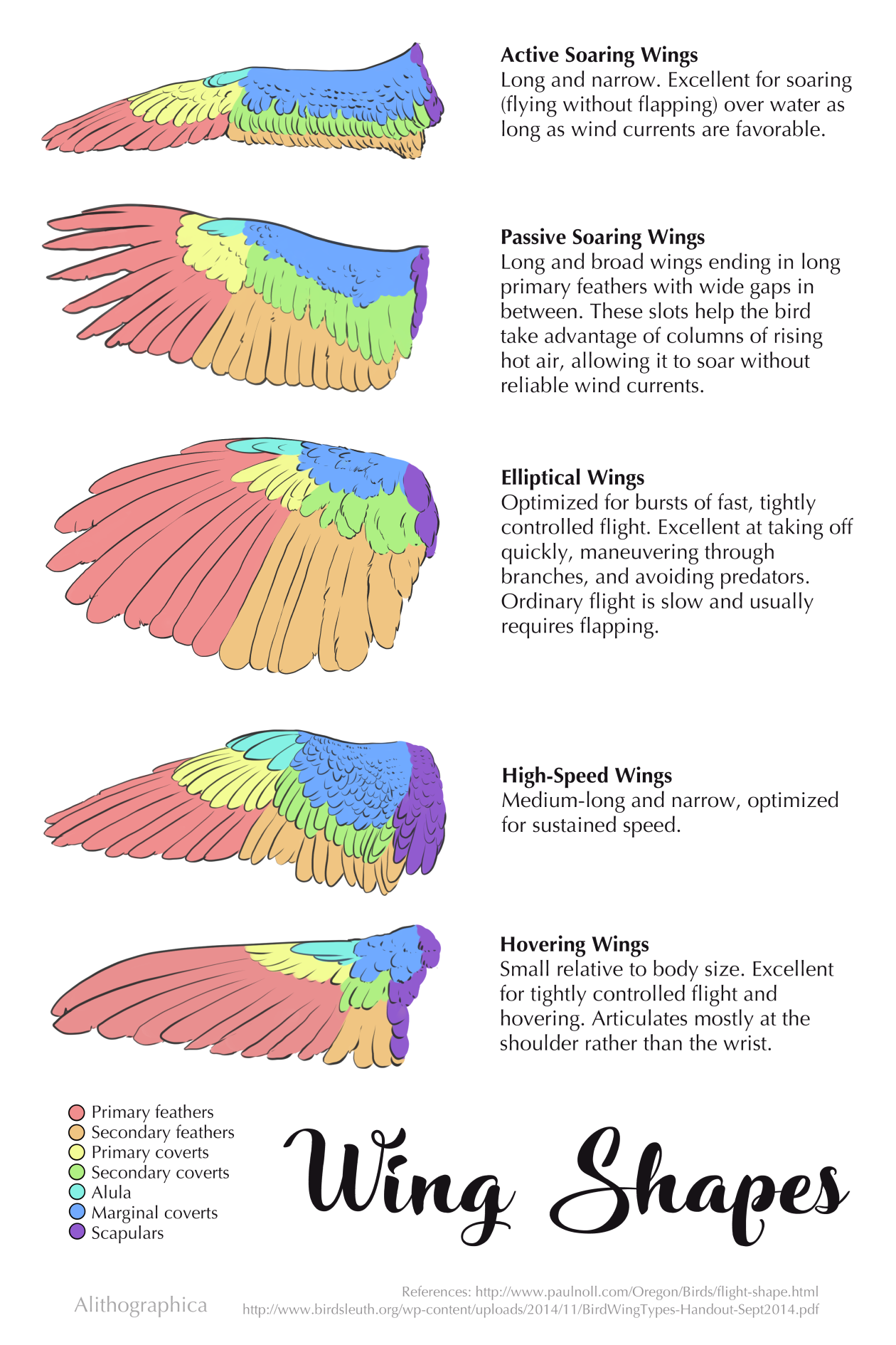
Sticking to our boat idea and getting inspired by the movement of bird wings, we tried to make sails for our kinetic beast. The idea behind it was to use the dithering movement of the bird tube to pull open the wings. So no external energy will be required to open the wings.

In theory, the wings should open whenever the bird tube declines. There are strings attached to the top of the bird tube. This string in turn is attached to the pulley of the wings. When the bird tube is stationery and parallel to the ground, the strings will hang loose as shown in the photograph with diagrams above. When bird tube declines and leans towards the kinetic beast, the strings will be pulled tight. This will make the sails open.

In our case, this theory did not work. As shown in the gif above, you can see the strings being pulled tight but this did not trigger the pulley. Which in turn did not trigger the sails to open up. The sails remained stationery while the string did alternate between hanging loose and being pulled tight. So only half of the theory worked out.
Potential changes could have been using a different kind of string. Perhaps the string we used was too thin and was not strong enough to trigger the pulley. Furthermore, there may be alternative ways to use the dithering movement of the bird tube to trigger an opening of sails. In addition, the problem with using the sails was not giving enough room for the bird tube to oscillate. As a result, the oscillations became smaller as well. Finding the right balance for the bird tube to oscillate is difficult and we did not want to add additional weight that might potentially ruin the balance. Also, there was no guarantee that the kinetic beast will sail with the wings either so for these various reasons we decided to eliminate the wings.


Plover birds are known to pluck insects or food particles from crocodile’s teeth. To imitate this motion and incorporate it into our kinetic beast, we thought of a magnetic dam.
In theory, when the bird tube tilts down towards the yellow acrylic sheet two things should happen. The water from inside the tube should pour out into a container and the magnet on the bottom of the tube should open up the container door. (Please refer to the illustration in the banner above) It would be like opening up a dam door.
In our case, it did not work out for several reasons. First, the magnet was not strong enough to lift something. Second, the bird tube has to oscillate back and forth. Once the dam was lifted it would stay stuck to the magnet and the bird tube. Thus the bird tube will be unable to oscillate because of this extra weight.
Potential changes could have been making a manual dam that opens when you pull it. But at the same time this solution is not in accord with our intention of using the natural dithering of the bird tube to open the dam.

The dictionary definition of thermochromism is property of substances to change color due to a change in temperature. As mentioned, both the crocodile and plover bird are attracted and influenced by heat. We decided to incorporate this characteristic into our kinetic beast.
In theory, when heat is applied to the thermochromism substance the color should change in a visible matter.

In our case, it worked. Brendan managed to order thermochromism powder that we mixed with water, acrylic, and white glue. This paste allowed us to pain the powder on a surface. When the surface meets heat either through the form of hot water from the fountain or a lighter, the colors changed. The GIF above demonstrates this color change. The top of the bird’s head changes from dark grey to transparent white.

In our final model, we applied this paste on the yellow acrylic sheet. The paste made the sheet look like a mossy green like the skin tone of a crocodile. When hot water is poured out of the bird tube, the color of the yellow acrylic sheet (as shown in the photograph above) changes.


One of the suggestions Professor Cheryl gave was a different version of the magnetic dam (number 4 above). Our final kinetic beast has a yellow acrylic sheet and hidden crocodile teeth beneath. Seeing this she suggested that we could have used the magnet on the bottom of the bird tube to lift a small portion of the acrylic sheet to reveal the hidden teeth beneath. This would have not only taken advantage of the dithering of the bird tube but also imitated the motion of a crocodile opening and closing its mouth. In addition, the teeth beneath would become more visible.


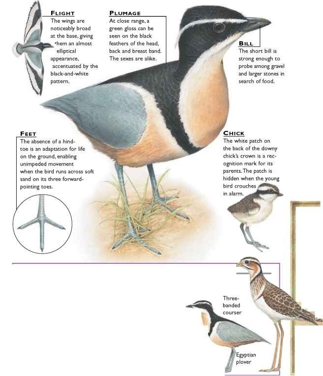
 This model was more focused on a realistic representation of the plover bird. In addition, it was taking into consideration of storing water in it and letting the water out as the bird oscillates back and forth. A paste that changes color when it is heated up was applied to the bird because both the plover bird and the crocodile is attracted to heat.


