Project done by: Emma, Wei Lin, Natalie, Wan Hui
Our multimodal project is called Feel My Message. This project aims to inform a person about the content of a received telegram message without being disruptive to his entourage.
CONTEXT:
Our device is ideally an unobtrusive small box that can be placed on the table or in one’s pocket. We envisioned it to be used when one is unable to check their phones or laptops for messages during a meeting. However, in our prototype, our device is bigger than what we thought due to hardware and financial constraints.
HOW THE DEVICE WORKS:
The device will first receive messages sent to the user from someone else via our telegram bot. Then, two separate dials within the device will rotate to indicate who the sender is and the content of their message. This information is depicted through tactile symbols that the user will be able to touch with a finger and recognize upon contact. To make this device universal, the symbols that represent the message content is changeable to better suit the needs of different users. Users can also assign their own contacts to the dial that represents the sender of the message.
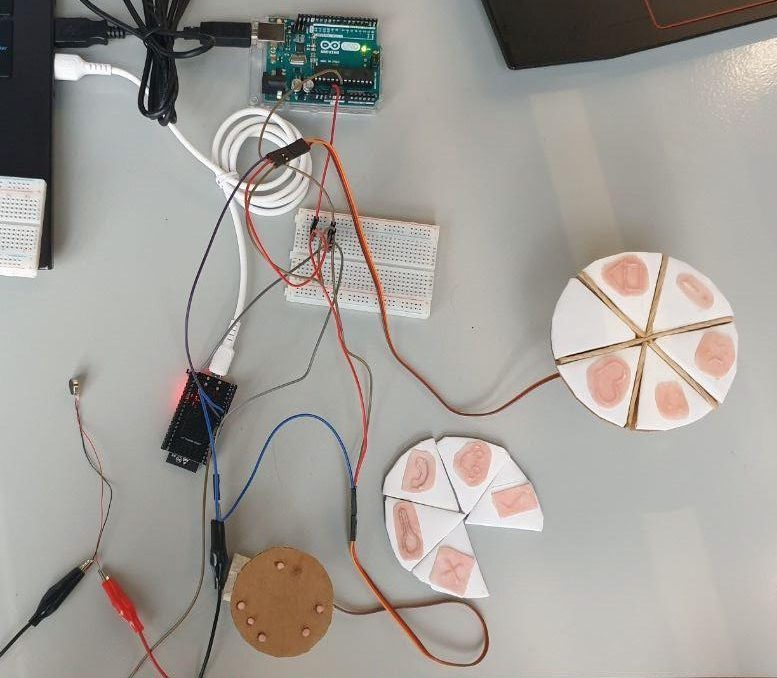
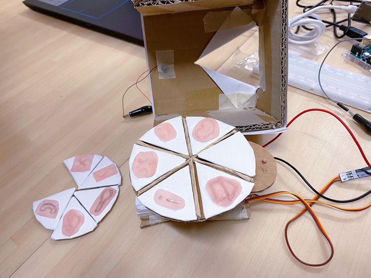
PICTURES OF THE UNCOMBINED PROTOTYPE:

For the symbols, we had prior prototypes before we decided on these symbols. We used plastic poly pellets to make the symbols because it was more forgiving when it came to the experimental stage because we could easily remould it, as we were still trying out which symbols worked best for what kind of message.
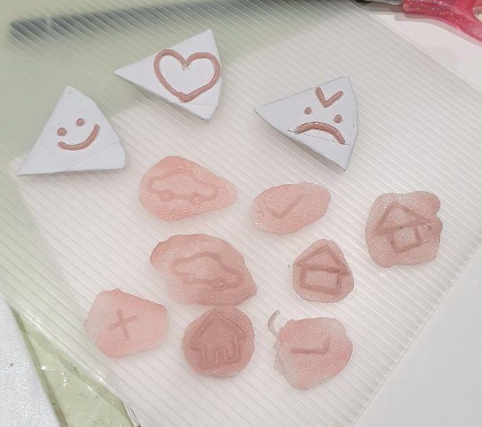 Before we settled on using a mould, we tried to shape the poly pellets into the symbol itself, but we realised that the symbols didn’t feel very obvious because it was too smooth to the touch. By using the mould, the finish was rougher and that was more obvious, hence we settled with using a mould.
DEMO:
HARDWARE:
- Arduino Uno Microcontroller
- ESP32 wifi and bluetooth board
- 2 x 360° continuous servo motors (MG90S + MG995)
- Vibration motor
- Breadboard
SOFTWARE:
- Arduino IDE
- Telegram Bot Maker
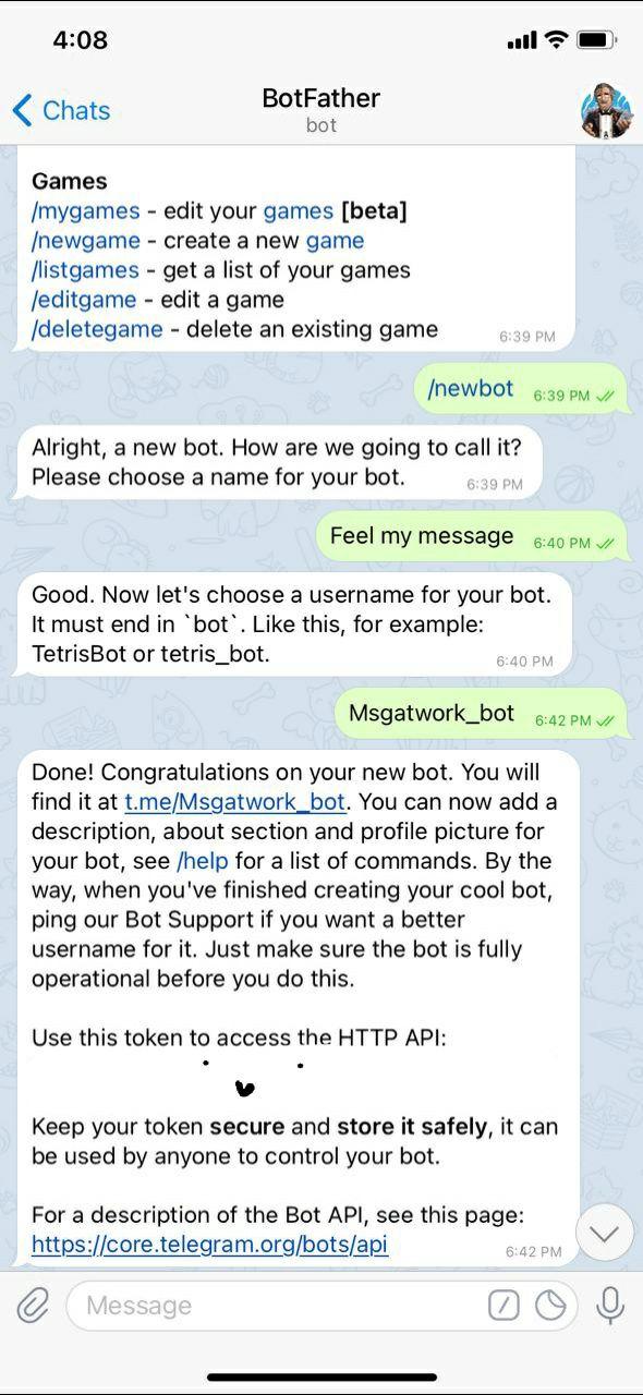
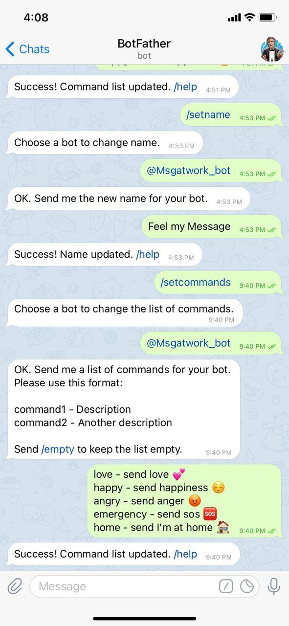
SETTING UP THE TELEGRAM BOT:
CHALLENGES:
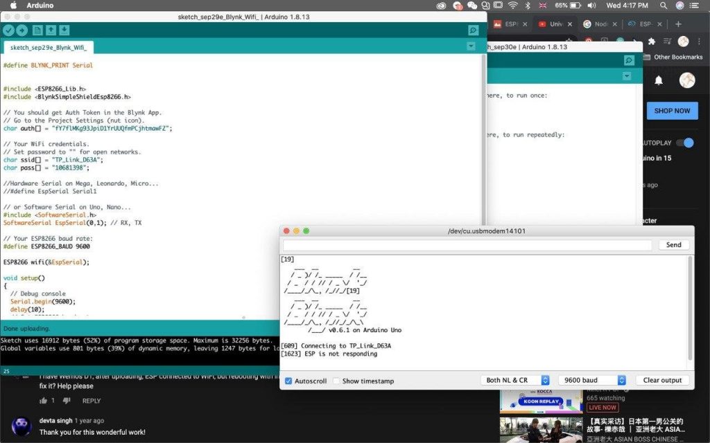
In the beginning, we tried using an ESP8266 wifi module with Arduino Uno, with the software Blynk to Arduino IDE. However we could not get the ESP8266 wifi module to work despite numerous attempts. It would not connect to the wifi or work with Blynk.
Afterwards, we bought an ESP32 wifi and bluetooth board. We tried having two separate codes on the ESP32 and Arduino Uno. We used the Arduino Uno to control the 2 servo motors (5V) and ESP32 to run the main code. We had to do this because the ESP32 runs on 3.3V while the servos run on 5V, so the ESP32 board did not have enough power to run the servos and the vibration motor. But by doing so, we were unable to get the Arduino Uno to communicate with the ESP32 via serial communication, because they were running on different baud rate (9600 vs 115200) and if we uploaded the code via the Arduino Uno, it would be unable to access the ESP32 library.
We attempted to connect the servos to the 5V or 3.3V pin on the ESP32. We were able to receive the messages, but yielded a weird error on the serial port, and the servos were unable to move. We researched that we needed a 5V to 3.3V logic leveler. However, we did not have a logic leveler available to us, so we had to think of an alternative.

In the end, our solution was to combine both our telegram bot code and servo motor codes into one main code, upload onto the ESP32 and use it as our main micro controller unit, then power the servos with a separate power source. We utilised the Arduino Uno as the 5V power supply through a breadboard. For this to work, the ESP32, as well as our other hardware had to all be grounded on the same line.
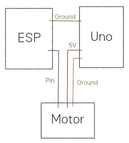
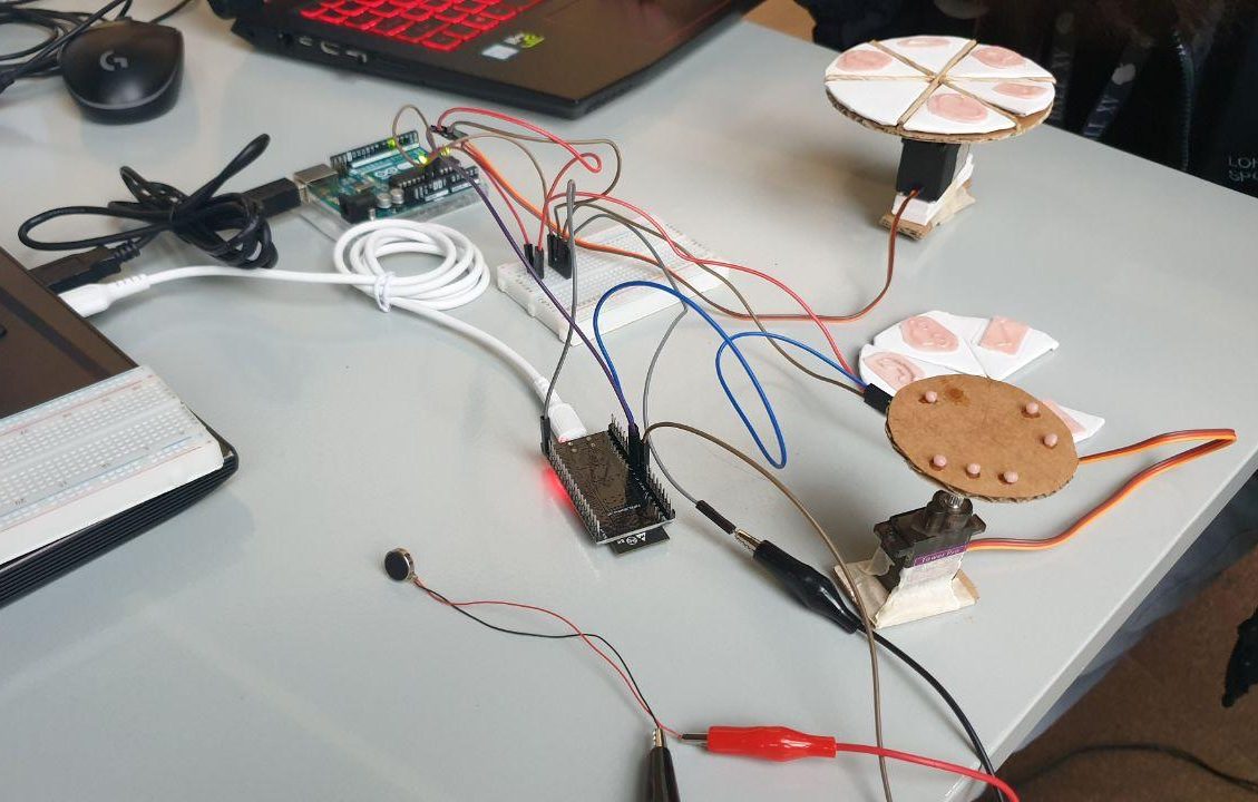
(how the wires are connected)
Now, there was sufficient power for the servo motors, we then moved on to combine the codes, making sure that the servos were working properly based on the received messages. Here is our final combined code.
FINAL COMBINED CODE:
#include <ESP32Servo.h>

#include <WiFi.h>
#include <WiFiClientSecure.h>
#include <UniversalTelegramBot.h>

static const int outerservoPin = 16;
static const int innerservoPin = 17;

Servo innerServo;
Servo outerServo;

int vMotorPin = 18;
bool ended = false;
String text, from_name;
int person = 0;
int msgsent = 0;


// Initialize Wifi connection to the router
char ssid[] = "XXXX"; // your network SSID (name)
char password[] = "XXXXXXXXXXXXXXXXXX"; // your network key

// Initialize Telegram BOT
#define BOTtoken "XXXXXXXXXXXXXXXXXXXXXXXXXXXXXXXXXXXXXXXXXXXXXXXXXXXXXXXXXXXX"

WiFiClientSecure client;
UniversalTelegramBot bot(BOTtoken, client);

int Bot_mtbs = 1000; //mean time between scan messages
long Bot_lasttime; //last time messages' scan has been done
bool Start = false;

void handleNewMessages(int numNewMessages) {
// Serial.println("handleNewMessages");
// Serial.println(String(numNewMessages));

for (int i=0; i<numNewMessages; i++) {
String chat_id = String(bot.messages[i].chat_id);
String text = bot.messages[i].text;

String from_name = bot.messages[i].from_name;

if (from_name == "Wan"){
person = 1;
}
if (from_name == "Emma"){
person = 2;
}
if (from_name == "Wei Lin"){
person = 3;
}

if (text == "/love") {
bot.sendChatAction(chat_id, "typing");
delay(100);
bot.sendMessage(chat_id, "Received love!");
Serial.println("lof from " + from_name);
msgsent = 1;
}

if (text == "/happy") {
bot.sendChatAction(chat_id, "typing");
delay(200);
bot.sendMessage(chat_id, "Smile! :D");
Serial.println("happy from " + from_name);
msgsent = 2;
}

if (text == "/angry") {
bot.sendChatAction(chat_id, "typing");
delay(200);
bot.sendMessage(chat_id, "Anger sent!! >:(");
Serial.println("angry from " + from_name);
msgsent = 3;
}

if (text == "/emergency") {
bot.sendChatAction(chat_id, "typing");
delay(200);
bot.sendMessage(chat_id, "Called for help!!");
Serial.println("emergency from " + from_name);
msgsent = 4;
}

if (text == "/home") {
bot.sendChatAction(chat_id, "typing");
delay(200);
bot.sendMessage(chat_id, "Welcome Home!!");
Serial.println("home from " + from_name);
msgsent = 5;
}

if (text == "/start") {
String welcome = "Welcome to Feel My Message, " + from_name + ".\n";
welcome += "Here is a list of commands for you to use :D\n\n";
welcome += "/love - send love 💕 \n/happy - send happiness ☺ \n/angry - send anger 😡 \n/emergency - send sos 🆘 \n/home - send I’m at home 🏠";
bot.sendMessage(chat_id, welcome);
}
}
}


void setup() {
pinMode(vMotorPin, OUTPUT);
innerServo.attach(innerservoPin);
outerServo.attach(outerservoPin);

Serial.begin(115200);

// Attempt to connect to Wifi network:
Serial.print("Connecting Wifi: ");
Serial.println(ssid);

// Set WiFi to station mode and disconnect from an AP if it was Previously
// connected
WiFi.mode(WIFI_STA);
WiFi.begin(ssid, password);

while (WiFi.status() != WL_CONNECTED) {
Serial.print(".");
delay(500);
}

Serial.println("");
Serial.println("WiFi connected");
Serial.print("IP address: ");
Serial.println(WiFi.localIP());

}

void stopturning(){
innerServo.write(93);
}

void vibrate(){
delay(50);
digitalWrite(vMotorPin, HIGH);
delay(500);
digitalWrite(vMotorPin, LOW);
}

void msg1(){
innerServo.write(70);
delay(640);
innerServo.write(93);
vibrate();
delay(5000);
innerServo.write(110);
delay(750);
stopturning();
}

void msg2(){
innerServo.write(70);
delay(1000);
innerServo.write(93);
vibrate();
delay(5000);
innerServo.write(110);
delay(1150);
stopturning();
}

void msg3(){
innerServo.write(70);
delay(1550);
innerServo.write(93);
vibrate();
delay(5000);
innerServo.write(110);
delay(1700);
stopturning();
}

void msg4(){
innerServo.write(110);
delay(1280);
innerServo.write(93);
vibrate();
delay(5000);
innerServo.write(70);
delay(1010);
stopturning();
}

void msg5(){
innerServo.write(110);
delay(750);
innerServo.write(93);
vibrate();
delay(5000);
innerServo.write(70);
delay(620);
stopturning();
}

void sendmsg(){
if(msgsent == 1){
if (ended == false){
Serial.println("msg1");
msg1();
msgsent = 0;
}
}

if(msgsent == 2){
if (ended == false){
Serial.println("msg2");
msg2();
msgsent = 0;
}
}

if(msgsent == 3){
if (ended == false){
Serial.println("msg3");
msg3();
msgsent = 0;
}
}

if(msgsent == 4){
if (ended == false){
Serial.println("msg4");
msg4();
msgsent = 0;
}
}

if(msgsent == 5){
if (ended == false){
Serial.println("msg5");
msg5();
msgsent = 0;
}
}
}

void per1(){
}

void per2(){
outerServo.write(180);
delay(270);
outerServo.write(93);
}

void per2back(){
outerServo.write(0);
delay(270);
outerServo.write(93);
}

void per3(){
outerServo.write(0);
delay(250);
outerServo.write(93);
}

void per3back(){
outerServo.write(180);
delay(260);
outerServo.write(93);
}


void loop() {
if (millis() > Bot_lasttime + Bot_mtbs) {
int numNewMessages = bot.getUpdates(bot.last_message_received + 1);

while(numNewMessages) {
// Serial.println("got response");
handleNewMessages(numNewMessages);
numNewMessages = bot.getUpdates(bot.last_message_received + 1);
}

Bot_lasttime = millis();
}
if(person == 1){
if (ended == false){
Serial.println("per1");
per1();
sendmsg();
person = 99;
}
}

if(person == 2){
if (ended == false){
Serial.println("per2");
per2();
person = 99;
sendmsg();
per2back();
}
}

if(person == 3){
if (ended == false){
Serial.println("per3");
per3();
person = 99;
sendmsg();
per3back();
}
}
}
Download our code here.