According to Isaac Asimov ,
the three laws of Robotics:
1) A robot may not injure a human being or, through inaction, allow a human being to come to harm.
2) A robot must obey orders given to it by human beings except where such orders would conflict with the First Law.
3) A robot must protect its own existence as long as such protection does not conflict with the First or Second Law.
Sounds really awesome isnt it, of course, there are situations that the robot will be forced to break these law, but again…. what if a robot is made to go against the first 2 law?
1) A robot may lightly injure a human when required to get the task done.
2) A robot may not obey all orders given to it by human beings.
3) A robot must protect its own existence and continue to execute the first and second law.
sounds really funny to me, doomsday robot? AHAHHAHA! sure, why not? ok maybe not. These laws are still in conceptualizing phase and if it made into the final project, it will be quite funny for those who read or knows the three law of robotics.
What was done until now after the last update?
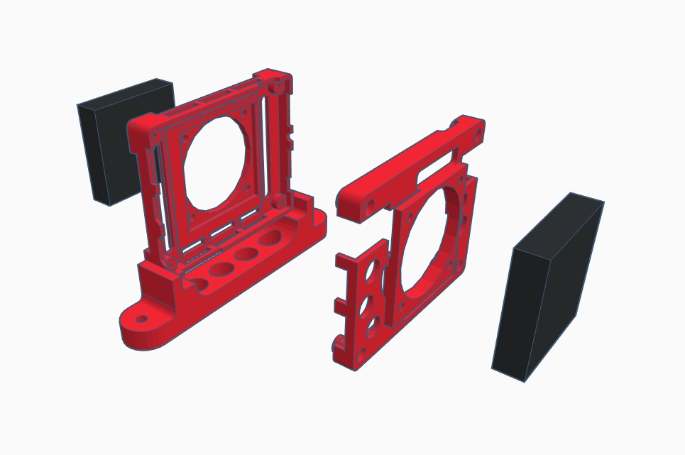
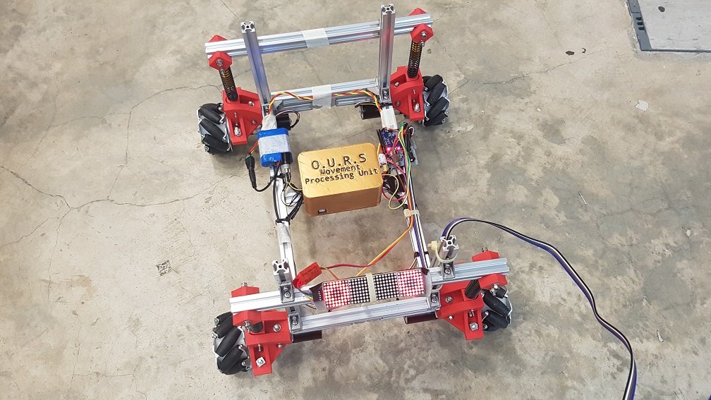
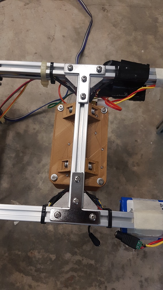
re-structure robot:
As of the previous update(the one before the presentation) whereby I’ve construct the wheel and the base structure for the robot, I’ve noticed that the parts get looser and looser even when I tighten all nut and bolt in every connections, that was because of the vibration when i move the structure around. To counter this problem, I’ve dissemble the structure and change all bolt and nuts to self-tighten nuts (Nyloc nut) paired with a spring washer to reduce the rate of it getting loose overtime. As a loose part will get looser overtime through vibration, if this was not done at the early phase(now), it will be a real hassle at the end as I want the robot to have a relative fast parts replacement (so no joints should be joined with permanent solution like super glue) and this solution of the combination of spring washer and Nyloc nut is the most effective solution for its cost(time and money).
Nyloc Nut, to “lock ” the nut prevent slippage of the nut:
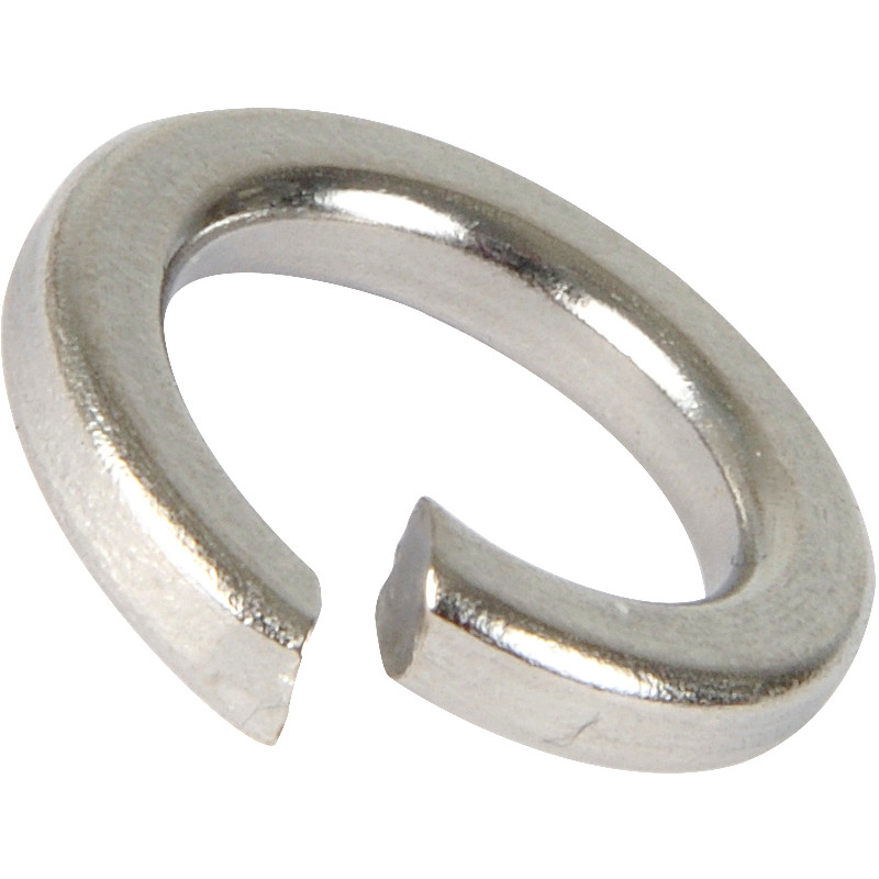
Spring washer, to prevent loosening through vibration
LED matrix animation:
The LED Matrix used is 4 x 1088 8 by 8 LED matrix which will be used as the animation for the eye of the robot, it will be attached to an arduino Nano which will be labeled as “Emotion Processing Unit” in this project to give it a more developed feeling to bring it away from the “Arduino = prototype” perception.
Parola Library code: Robot eye library code:
 animation made through a program that convert animation to LED matrix codes:
Mecanum wheel coding:
The Mecanum wheel is controlled through a 5 wire motor(VCC,GND,PWM,Dir and FG wire) so the motor driver was not required and I could wire them directly to an arduino. all the code was stored and run through an Arduino Uno whereby the main switch to control the motors were linked to a relay for the motor circuit. As mecanum wheel move unlike a normal wheel, special codes were used to move the robot in any direction without changing the orientation.

Master-Slave Arduino System
There is a function of Arduino that is called the master and slave relationship, whereby a master arduino could communicate with other arduinos(up to 52) through just two analog pin (A4 and A5), this is really helpful for my robot as there was the saying of “Do not put all the egg in a basket” and this function will ease my repair if any parts gets faulty during the FYP show, I could just switch out the problematic parts without re-wiring the WHOLE 5 bazillion wire connections. Also, Arduino is a single thread micro-controller(it can only do one task at a single moment) so by splitting up different processing requirement into different arduino, I could run multiple thread without any lags between them. Finally for the upside of a Master-slave system, it is simply to solve the problem of hardware problem of the limited digital pins each arduino have(more arduino = more pins I could utilize without having more parts/coding like using a I2C Address chip.
wiring diagram
Things are getting technical here…
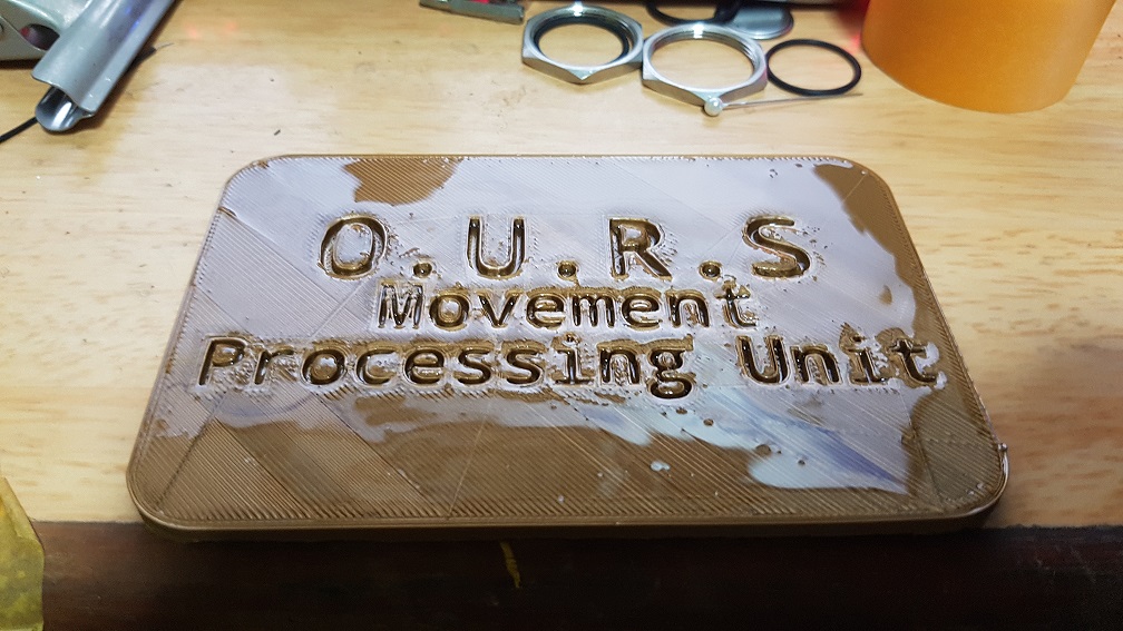
The Wiring Diagram, as messy as it looks but in normal language, a Master Arduino is controlled by a clickable analog stick (mode 1 to move, mode 2 to rotate), the data is processed and sent over through Analog Pin 4 & 5 to the MPU and EPU which “Movement Processing Unit(MPU)” that controls all the movements of the motor and “Emotion Processing Unit(EPU) controls the eye Animation on the LED Matrix. All of the Arduinos and motors will be paralleled connected to the 12V battery supply to power them up.
O.U.R.S Chief Engineer at work:

Sample Movement of Explorer 27:


 To experiment with speed and delay of Lattepanda with unity to control arduino, which is not bad!