Interactive Devices Final Project: Obsoleting Instruments Process 3(Final).

Continue from my previous Process 2.

again, I had progressed much further since that post, mainly in designing the workable electrical and mechanical system that could fit into the Telephone and to write the Arduino code up.

First, lets start with the Final Video!


Back into the Process

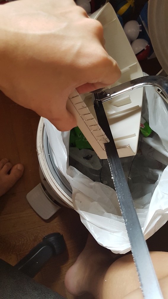
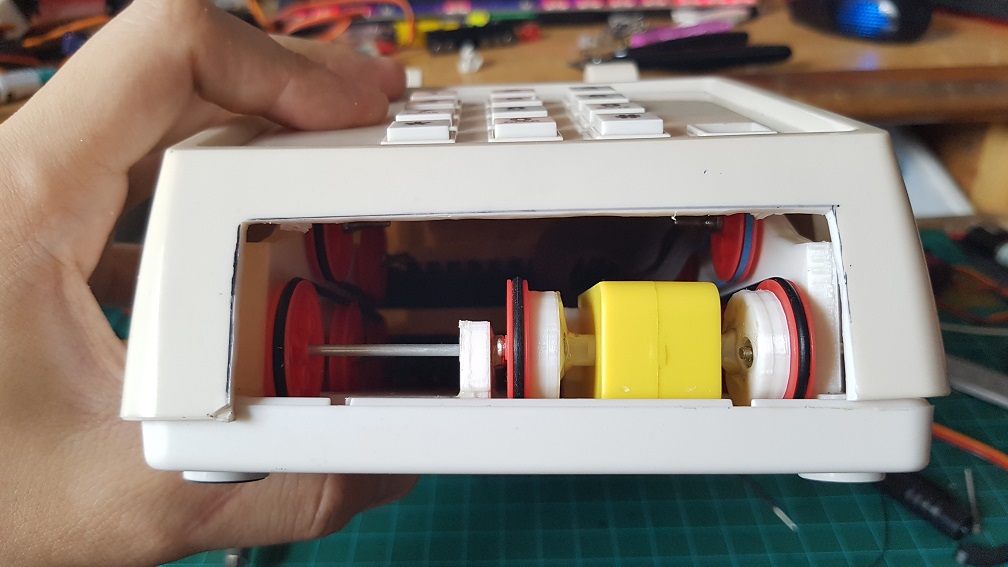
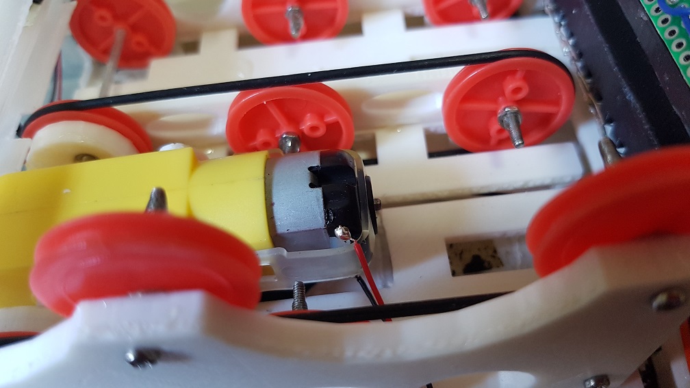
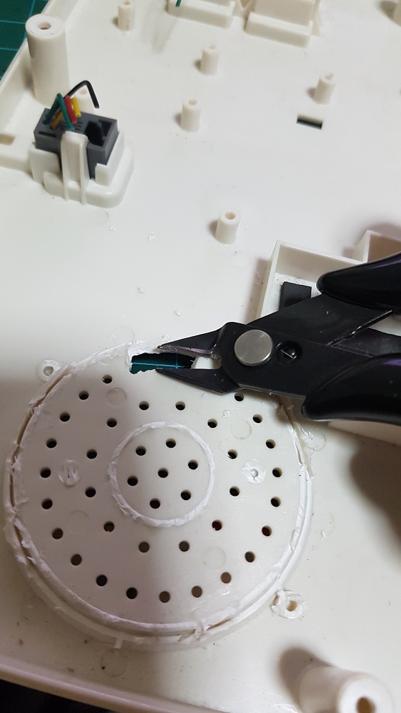
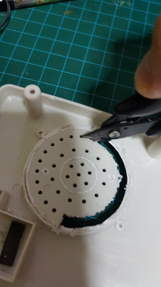
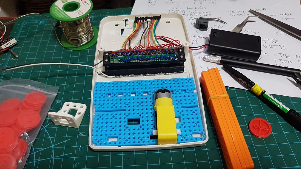
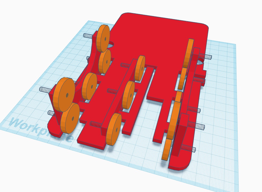
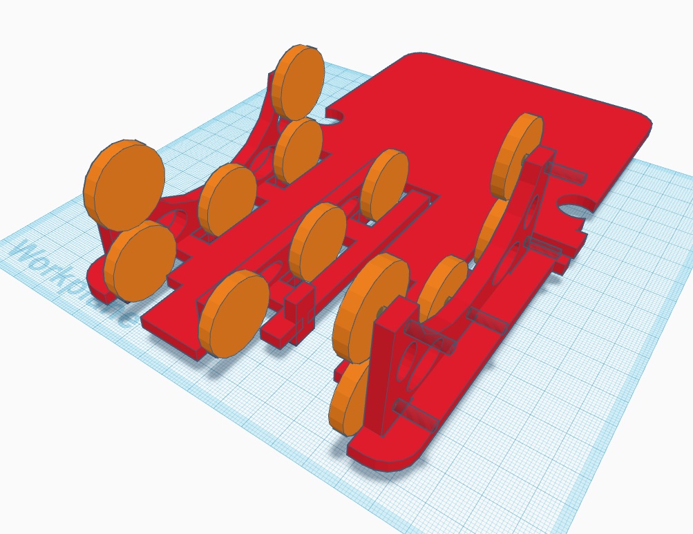
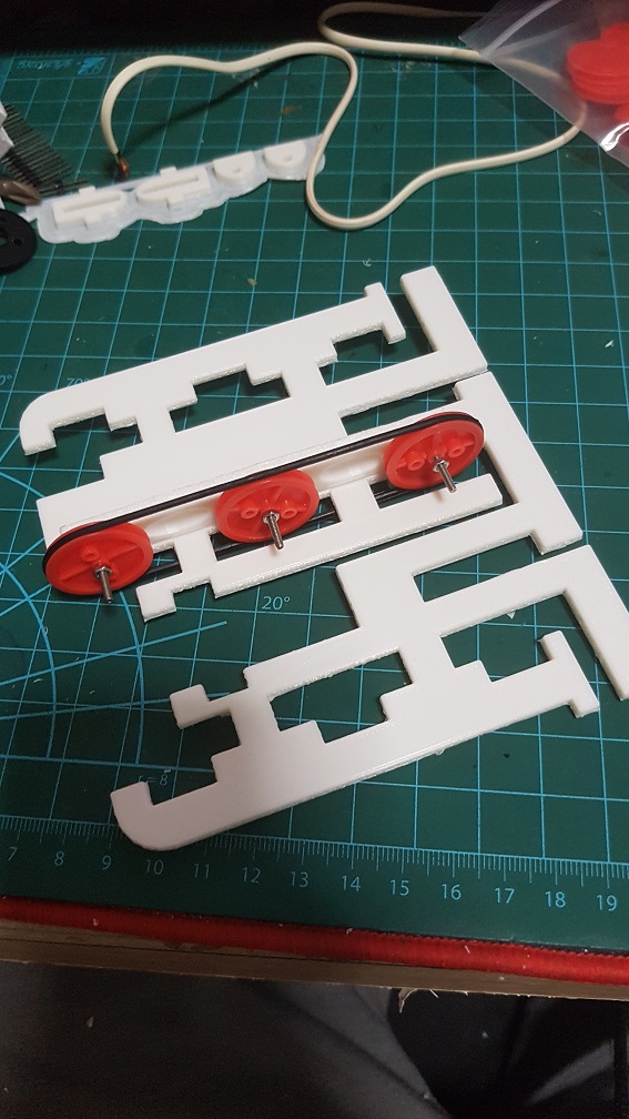
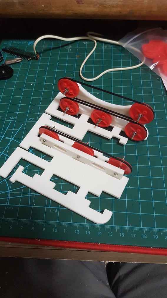
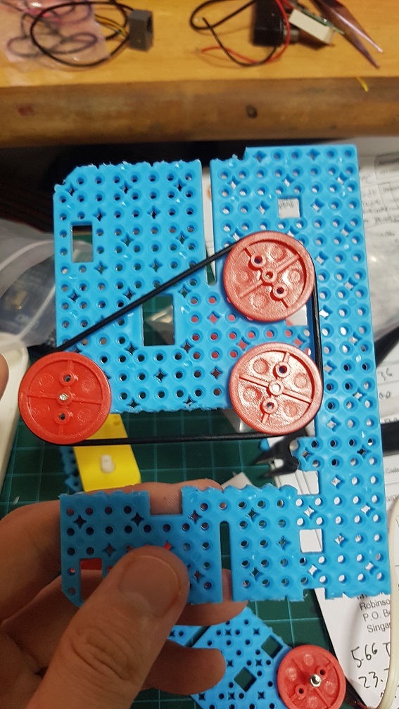
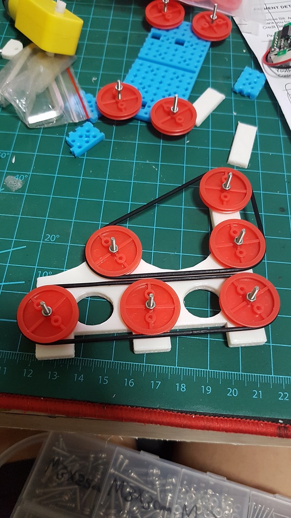
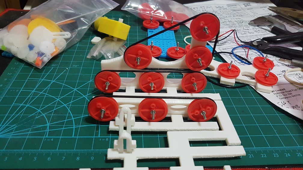
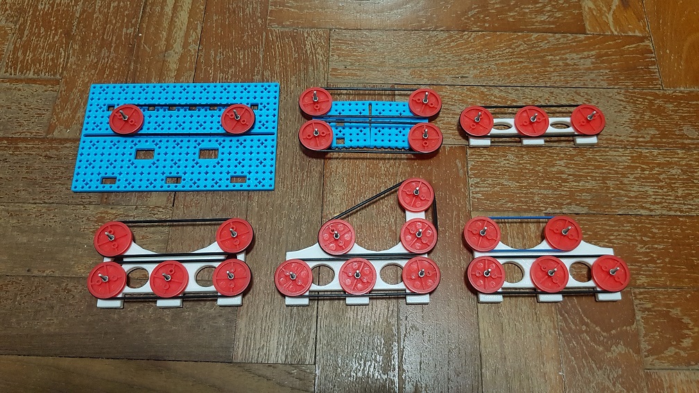
Since the previous post which I’ve roughly did the belt system that drives the music card into the laser reader, I had added the motor to the system and tried it, at this point, it seemed to work as I thought all I need was to slow the motor down and it will be alright.

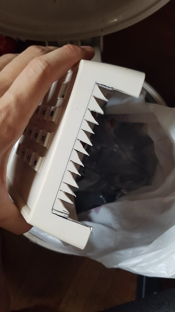
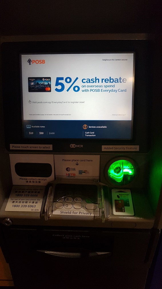
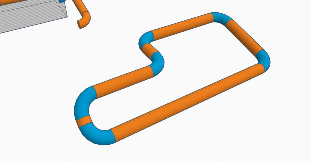
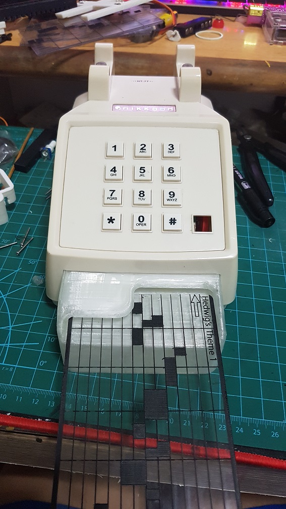
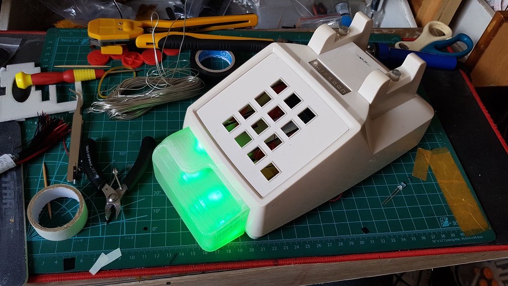
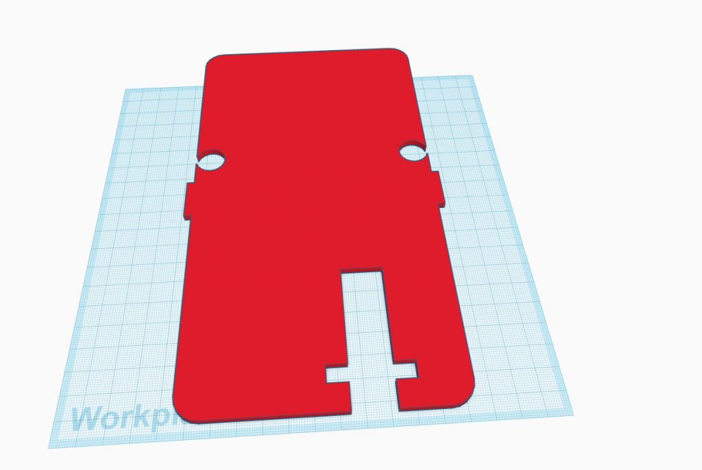
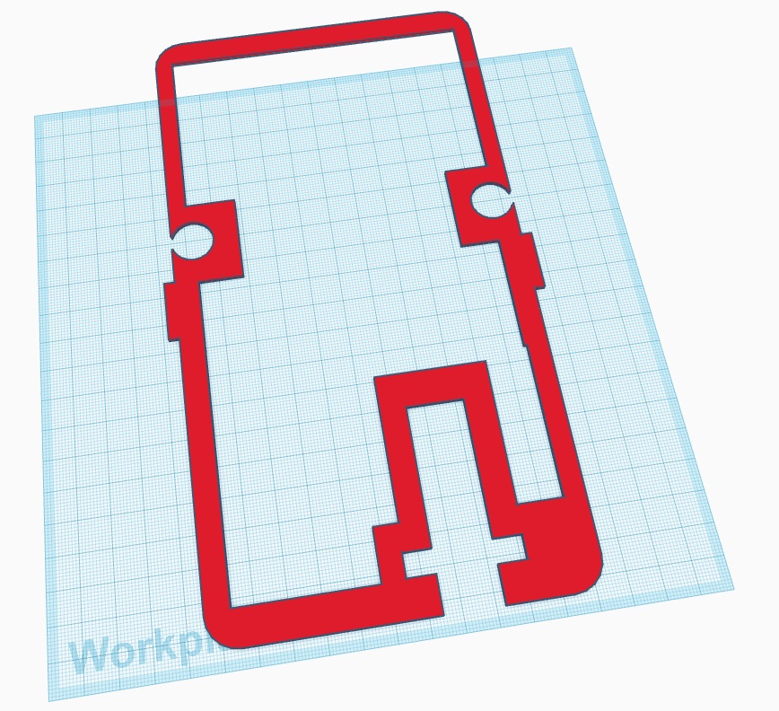
After I cut the hole, I proceed to modelling the card slot and i took inspiration from the ATM just to have the user to have something they’ve experienced and know how to put the Music Card in without instructing them, since subconsciously, I assumed that they interacted with a ATM at some point in their life.

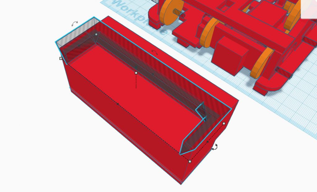
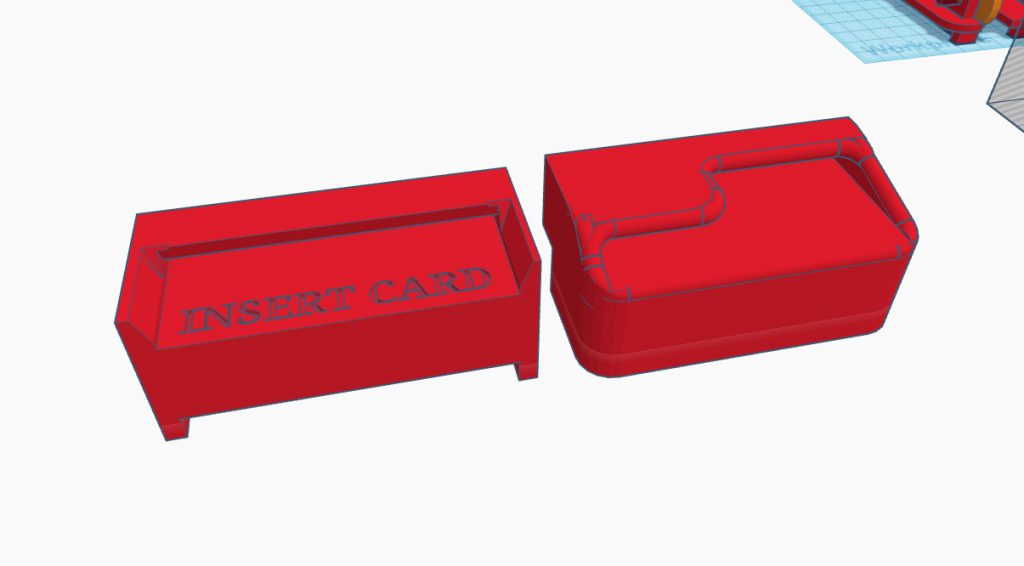
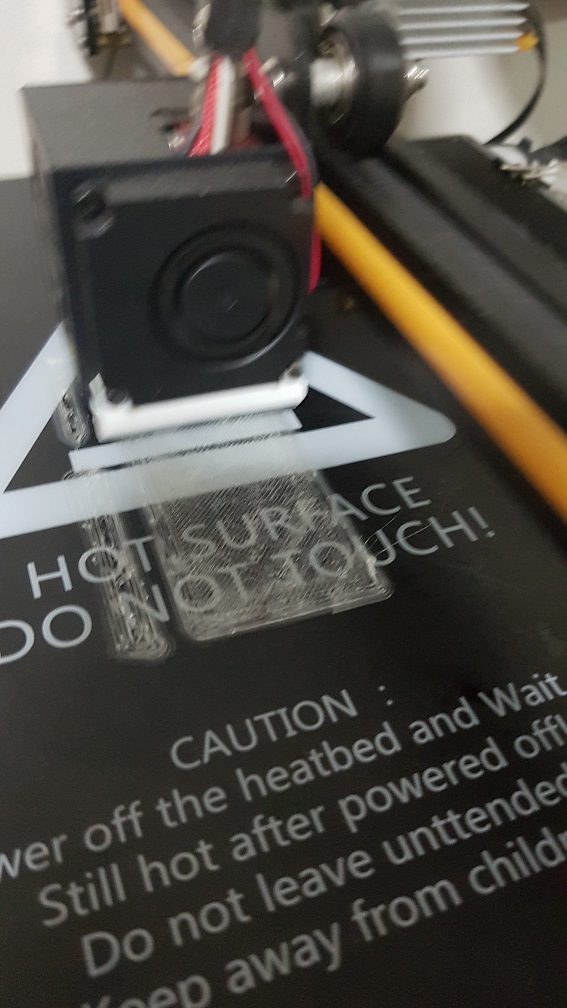
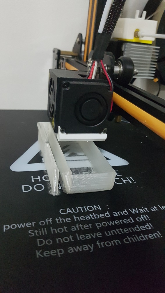
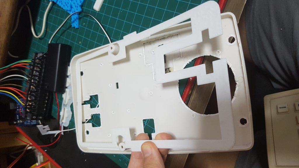
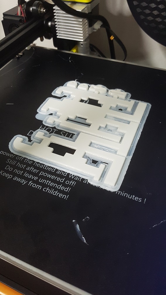
After the modelling which i am really happy with, I proceed to print it.

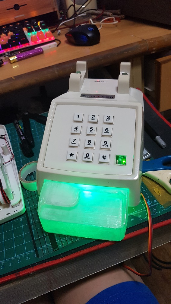
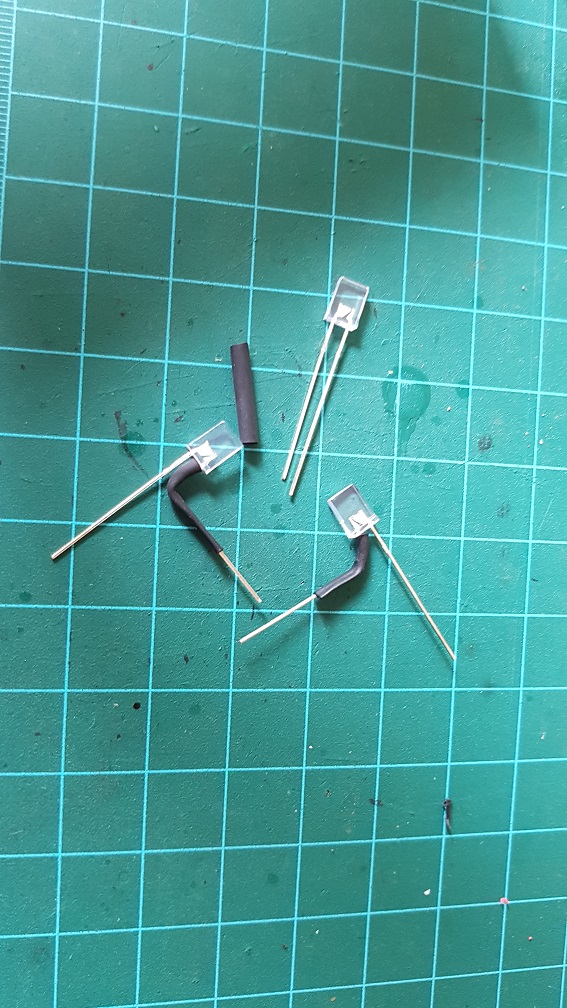
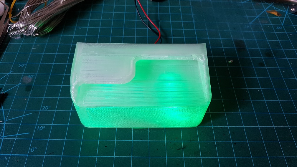
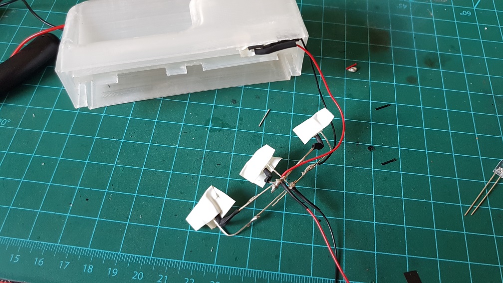
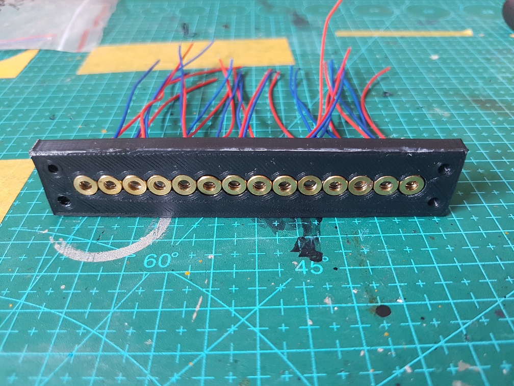
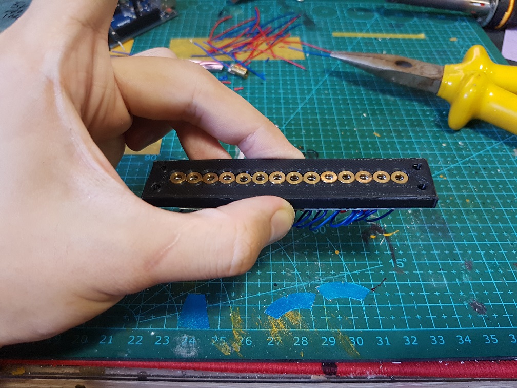
Since it was looking good, I went ahead and make a nicer LED system for it by soldering 4 LED(3 on the bottom and one for the top).

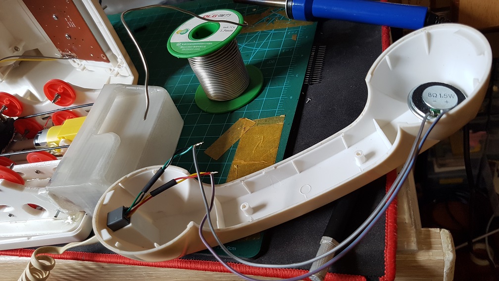
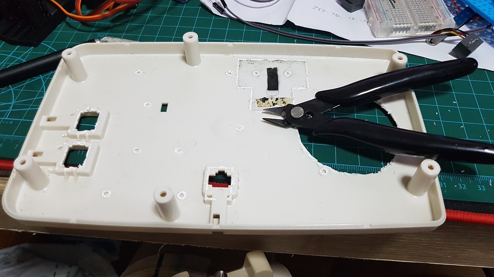
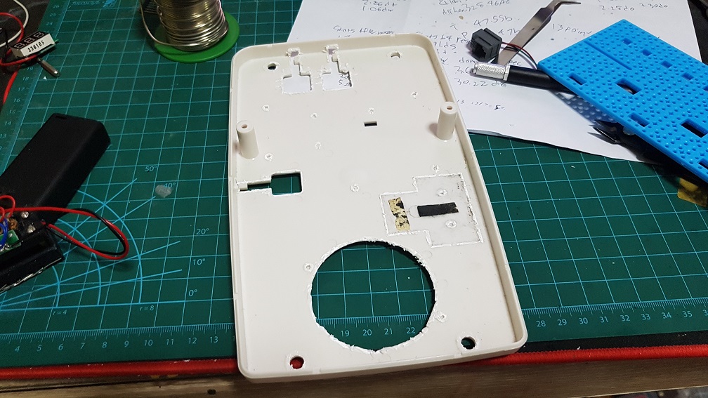
Next, I Epoxyed the speaker onto the bottom of the front belt drive since there is already a hole in the bottom shell for the speaker.

This is a 8 Ohm 0.5watt speaker that will be plugged directly into the Arduino.


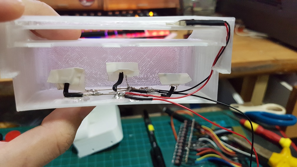
I also Epoxyed the 4 LED into the card slot to prevent them from sliding around.

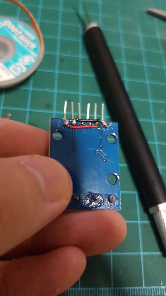
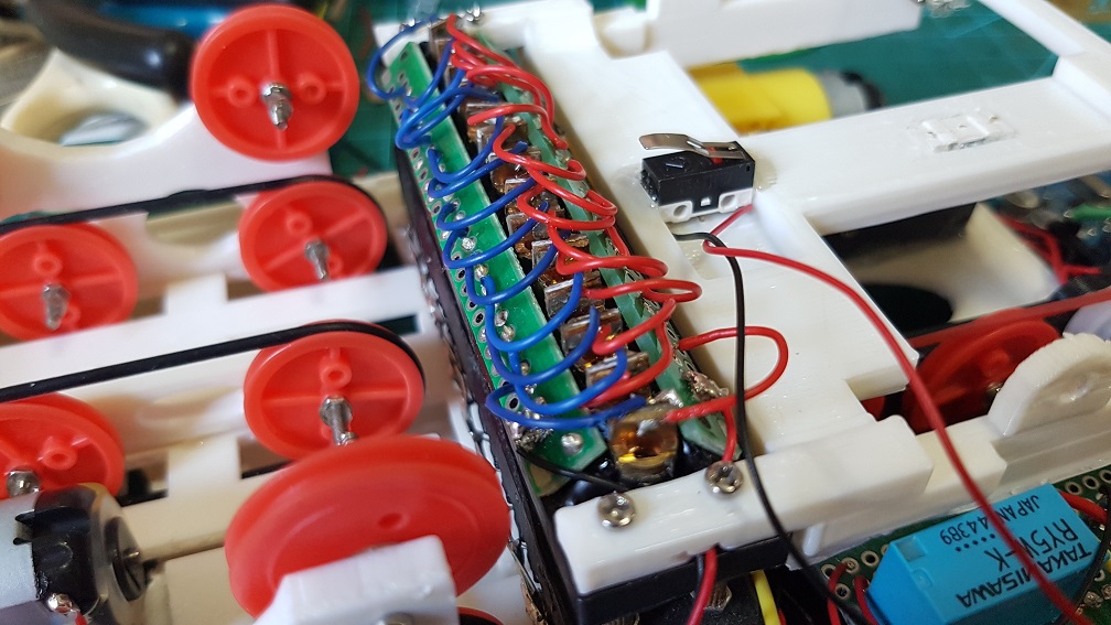
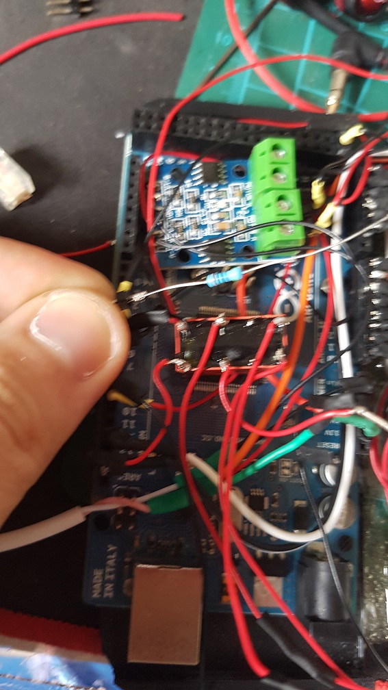
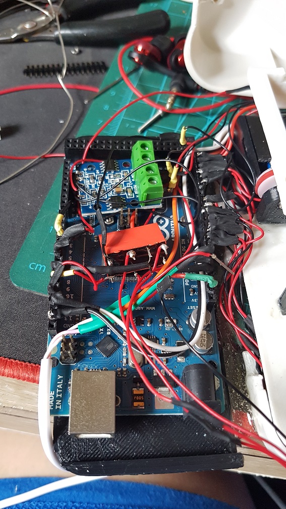
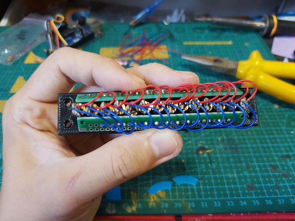
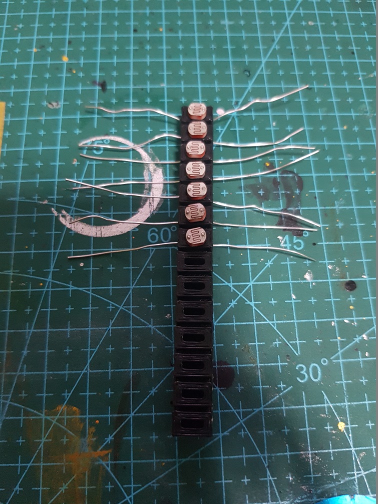
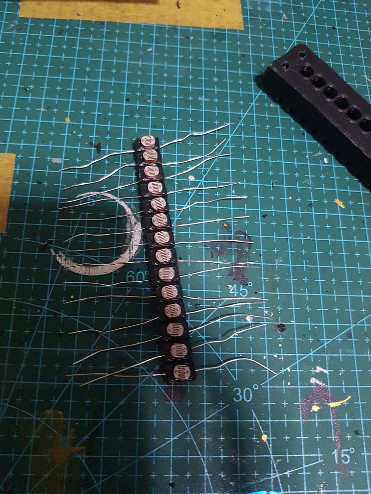
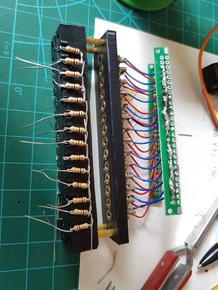
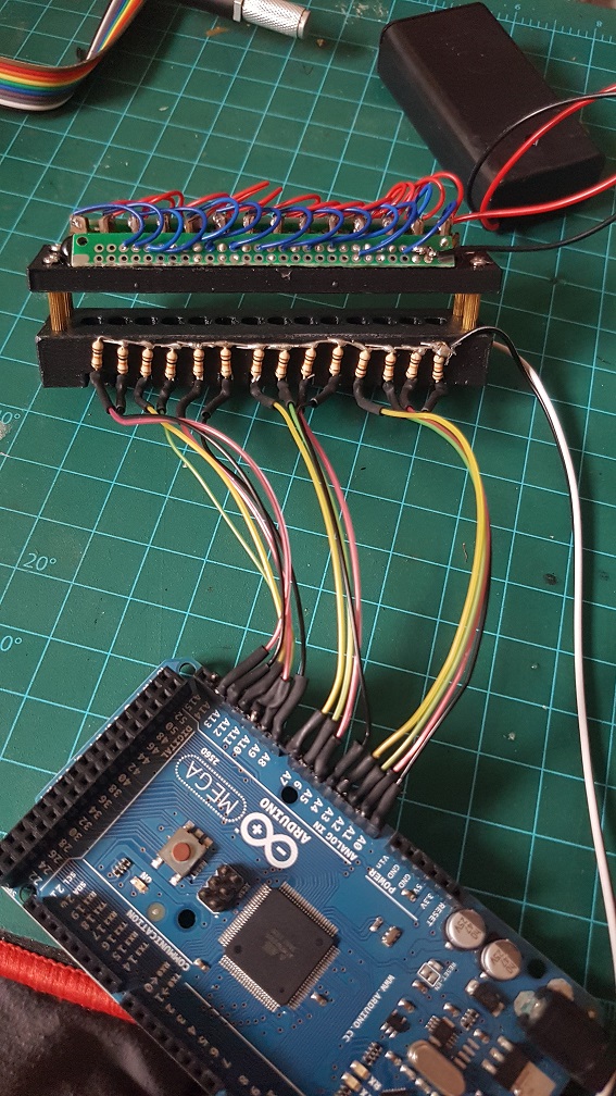
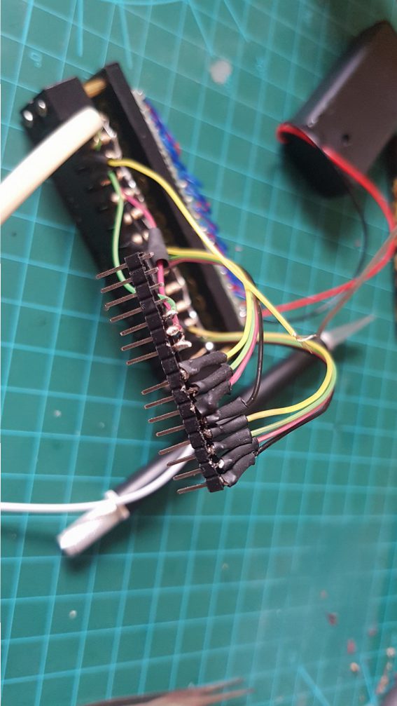
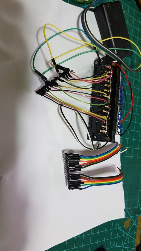
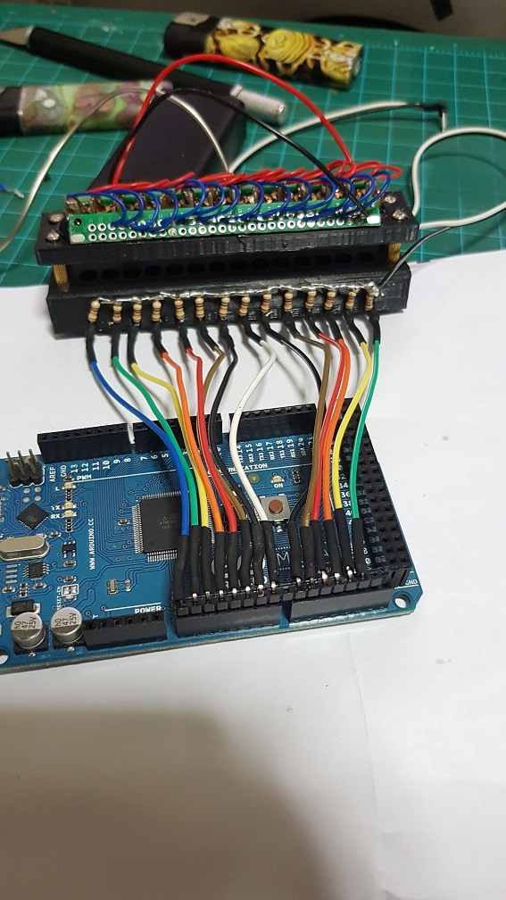
And came the soldering party.

It was at this point then I realized that if i reduce the speed of my DC motor to the speed of the music, I wont have enough torque to pull the card in..


After an afternoon of panicking and finding alternative motor or even thinking to redesigning my whole belt system….

I opened up the current DC motor to see if i could make modification by changing the spur gears to worm gear, which will increase torque and lower speed(after i did some research). but this require me to rebuild the whole gearbox as well as to remodel+reprint the whole of the front and back belt system.

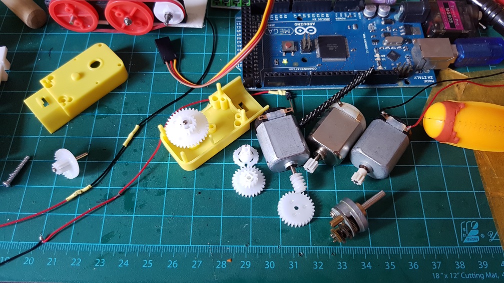
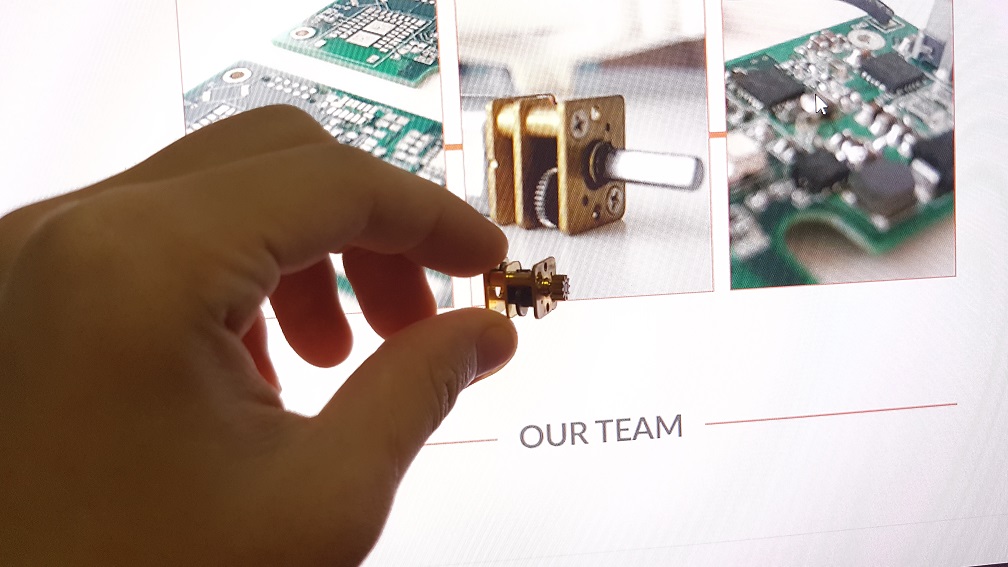
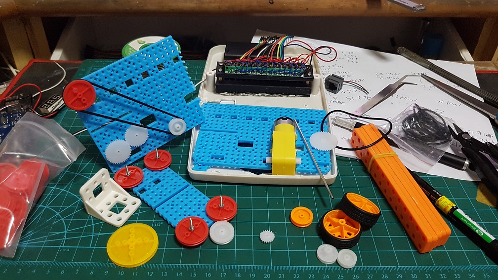
And then I found that I have a longer DC motor with metal gears built into it and i tried to figure our if I can incorporate this gear box into my current system, which is also rather impossible as the ratio for this gear box is about 1:45. when I only need about 1:5 to 1:8. if i use this, I will have the belt driver running too slow. 
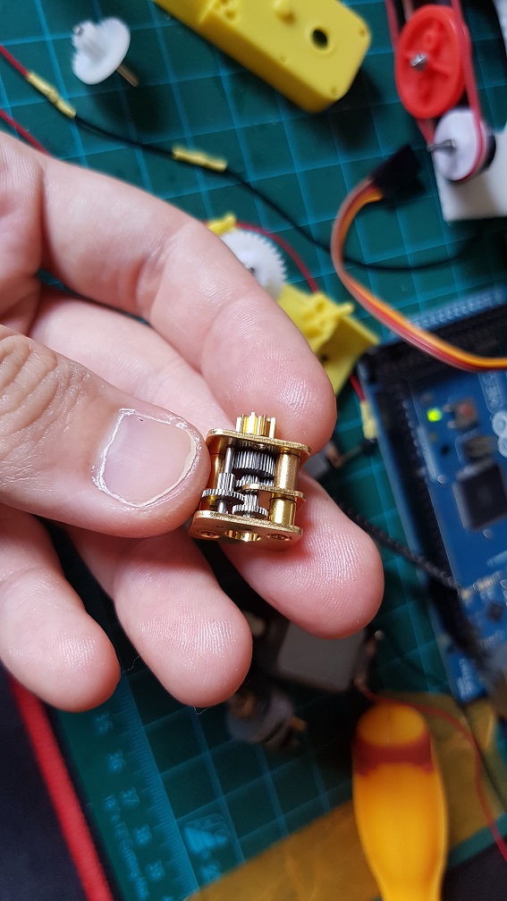
same goes for this, but this is 1:250… even slower.

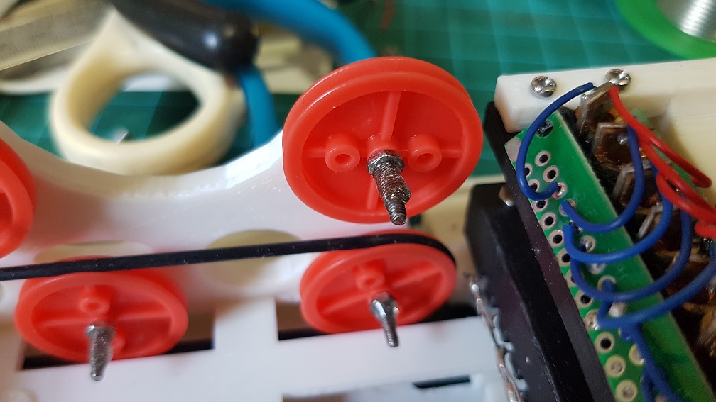
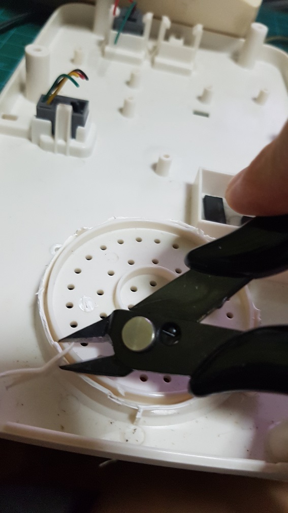
So to solve this problem, I tried to get the medium speed which is faster than what the song should be and will stuck about 30% of the time and removed the buttons (which detects card when user insert into it that trigger the motor to turn the belt.) that caused more friction. And I also jump start the motor by making it to spin at full speed for half a second to break the initial force required when the motor is starting.

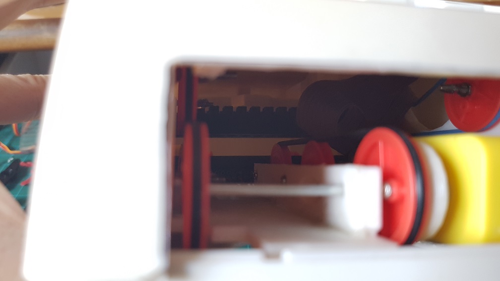
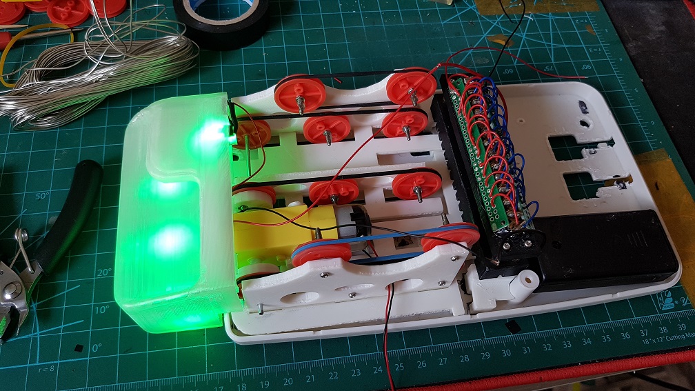
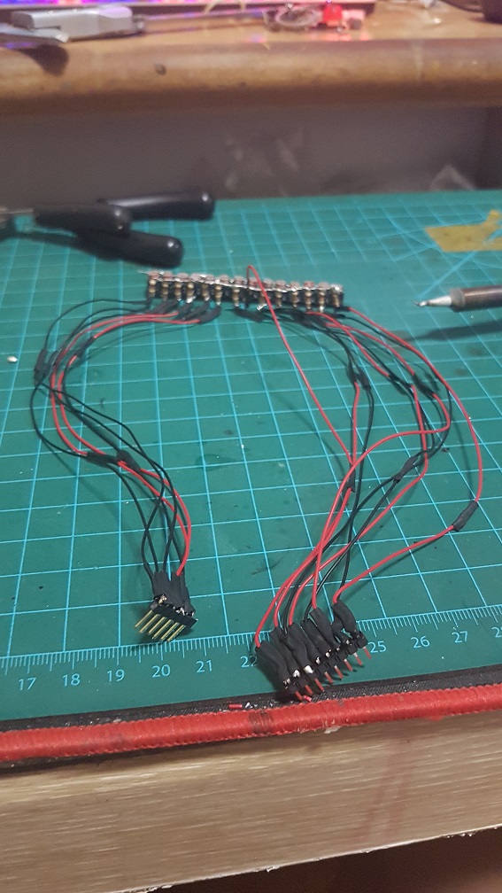
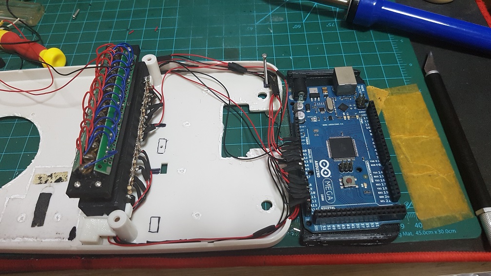
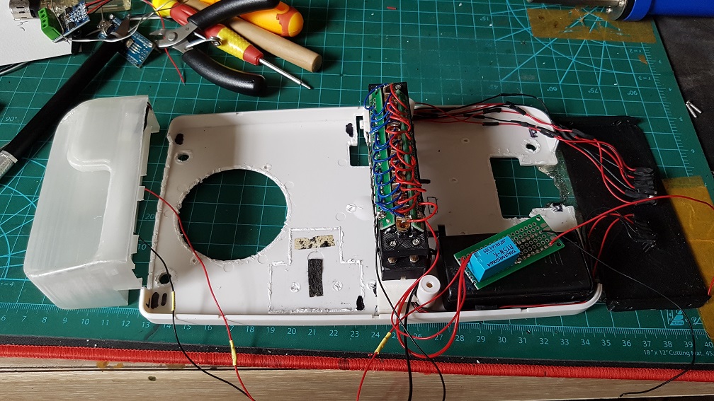
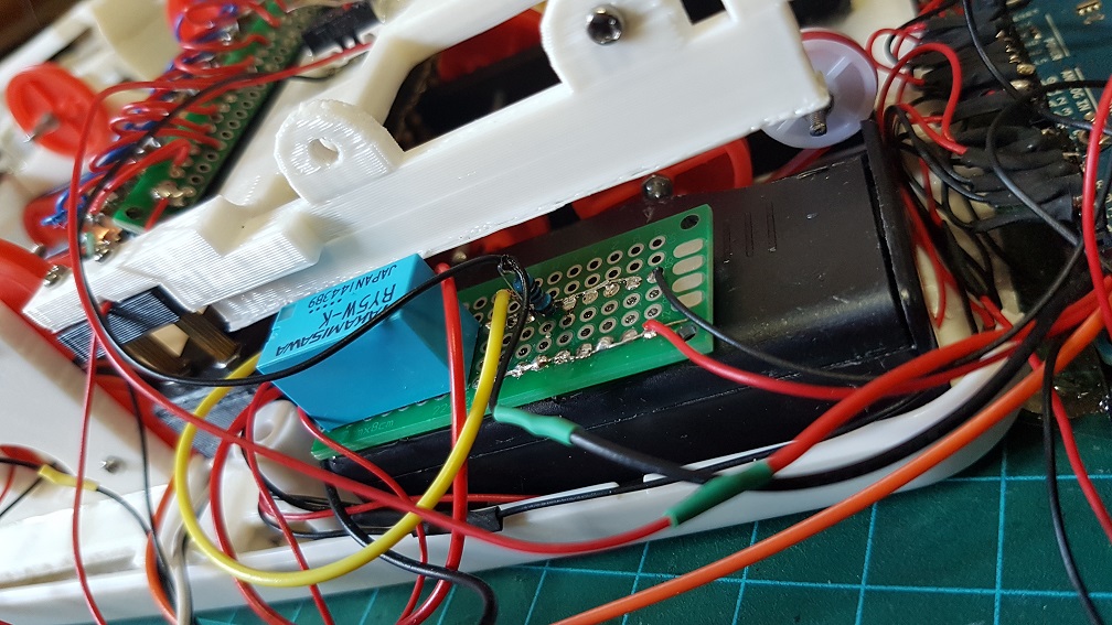
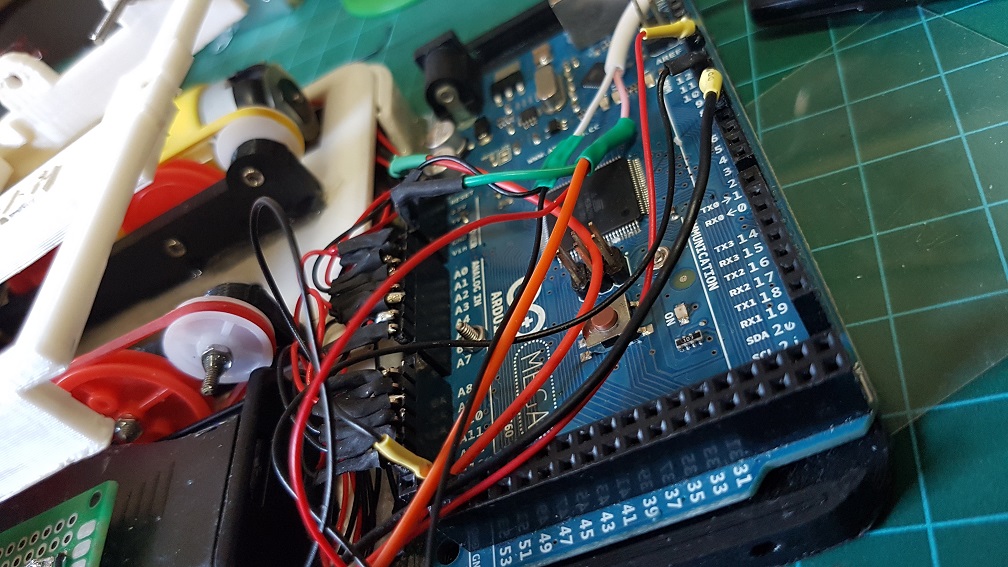
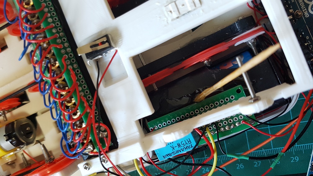
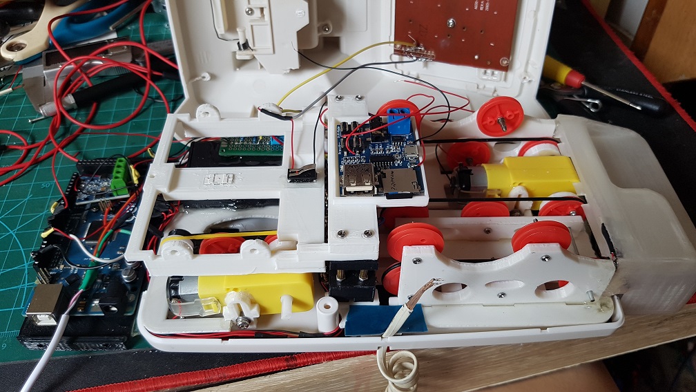
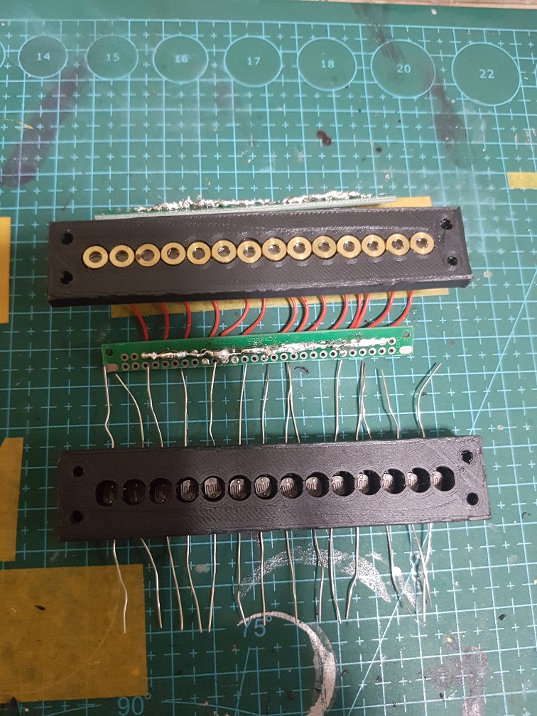
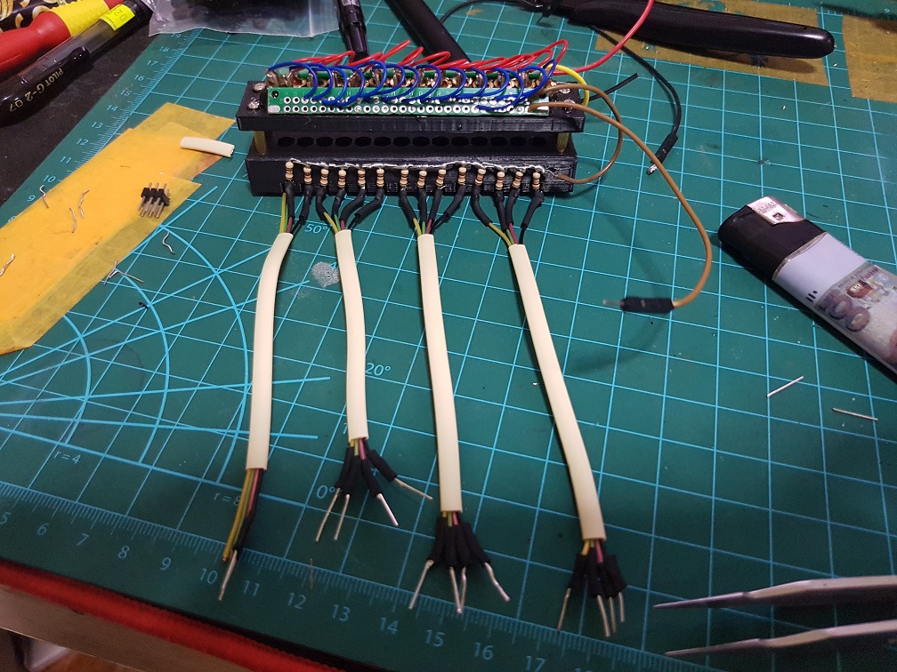
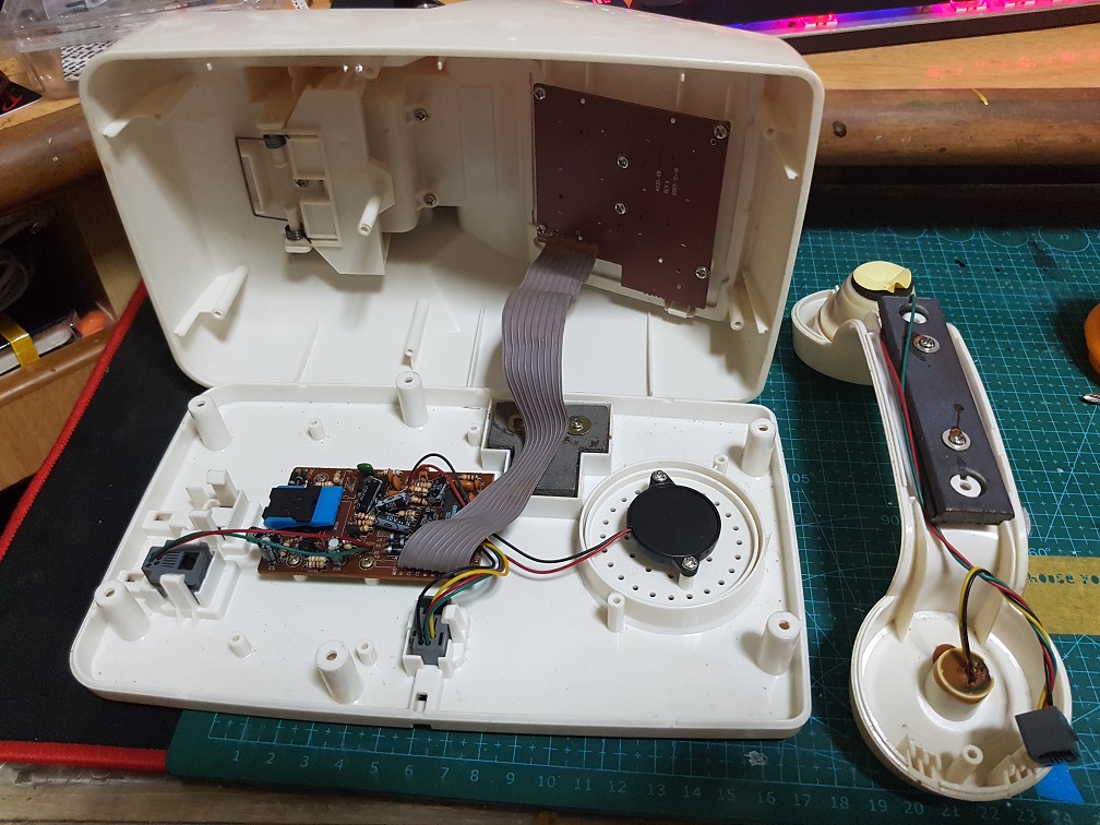
The messy configuration, components and wirings.

It took me some time to sort out these messy wiring and make sure that none of the wires interfere with the track that the Music card is going through.

after trying out the workable speed of sound and getting stuck by removing the buttons.

and after this, I tried to code the majority of the code together.

For this, I did not expect to work this well and I am really excited about it!

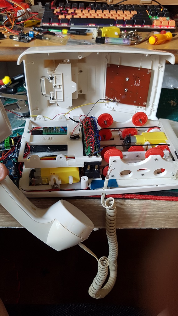
Towards the end of the project.

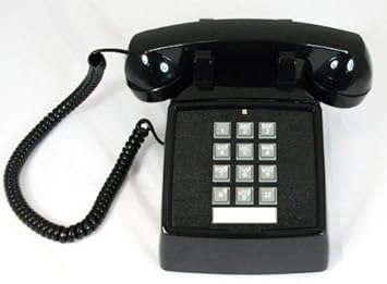
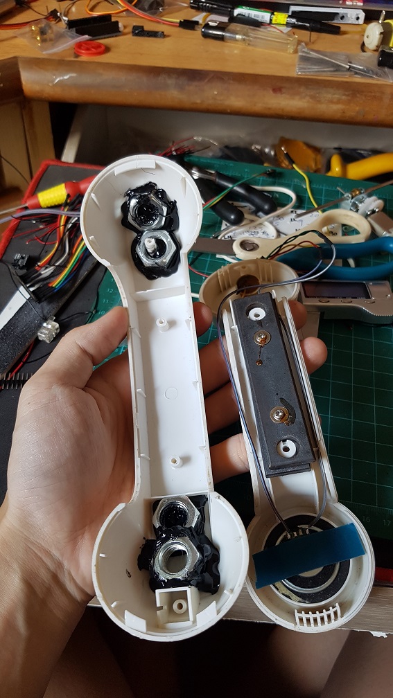
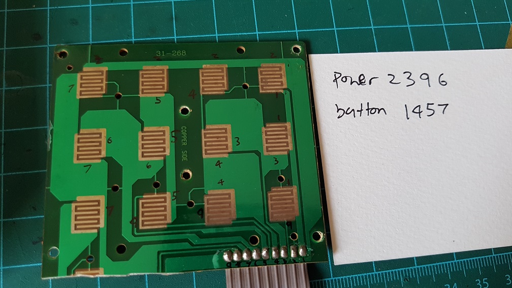
to make use of the original button on the phone, I’ve figured that the 12 buttons runs on 2 different circuit which I could simply solder these number together and make all the 12 buttons into one button, so nomatter which buttons the user pressed, it will be registered as one button pressed.

Because I cut off the Redial button on the phone to make space for my belt driver system, I epoxyed the Redial button back to the case as there are no PCB supporting it.

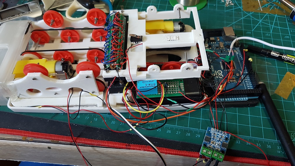
Some may wonder how did I make the Music Card..

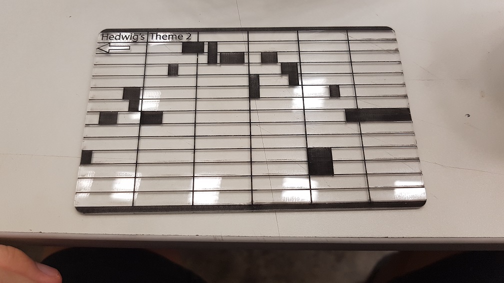
I copied a few from online like Demons by Imagine Dragons, Harrypotter’s Hedwig Theme, and Pokemon Theme song, These were labeled on the card and those that weren’t labeled was What I composed myself. Since I have no music background, I did it by trial and error to give it a tune.

This was screen recorded when I tried to compose my 4th tune for this project:

after this was completed, I screen shot it and import into Illustrator to trace it into the Card layout which I made.

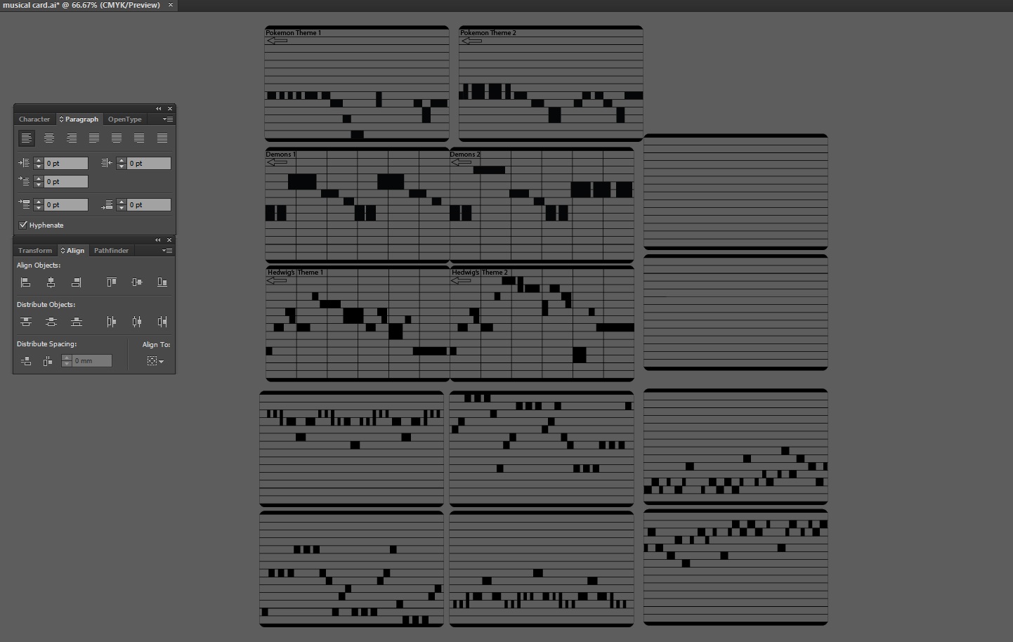
and this was how the cards were made.

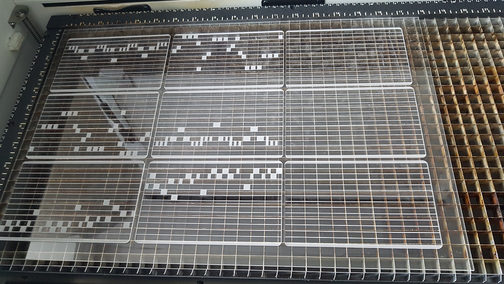
Laser raster and cut in school on 2mm acrylic.

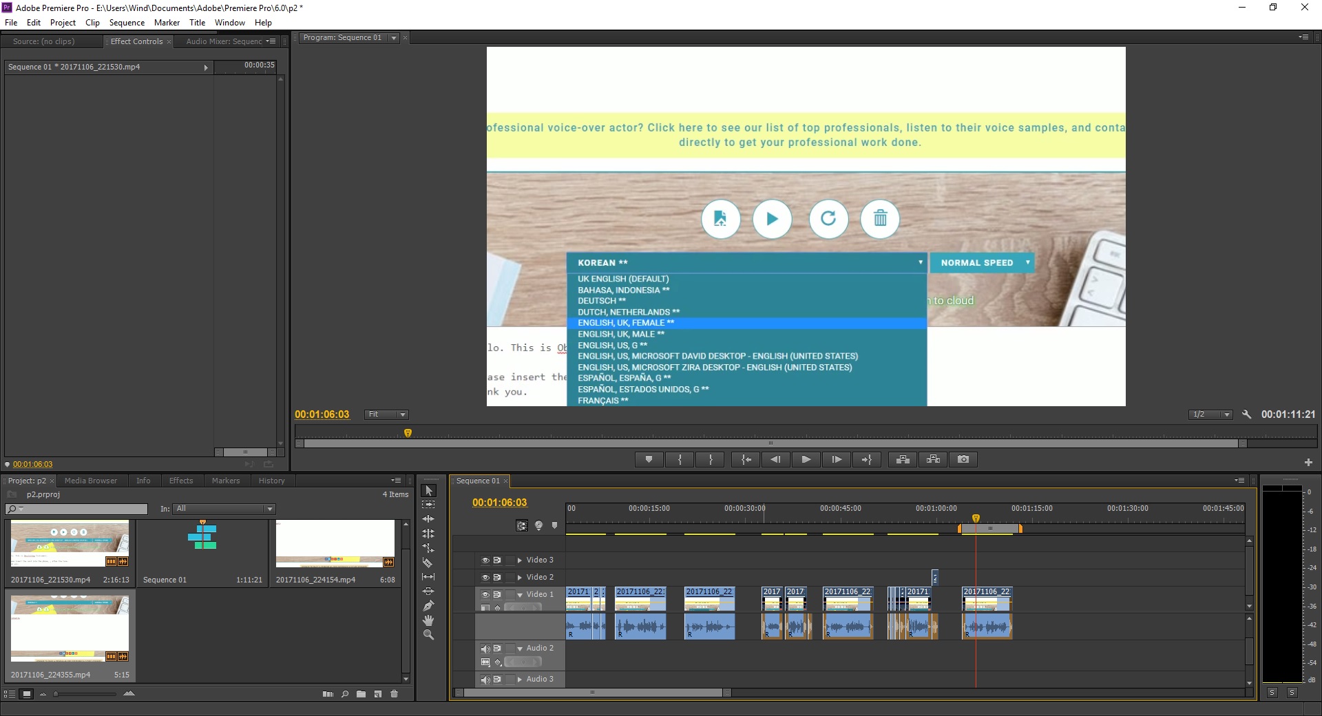
AND how about the voice command in 7 different accent?

well, this is relatively simple, just type whatever I want on Webbased Text to speech reader and have it read it out in different accent and edit them in premiere pro to cut them up to the exact same length(9 seconds) and put them into the SD card within the Obseleting Instrument’s MP3 Decoder.

I really like the Japanese and Korean accent, its really funny!

Why did I made it to speak different accent? It was to engage the user and make them feel like there was really life in the system where they called/receive call from a real person, like if they discussed with their friend and their friend said that there was a Indian accent while what they heard was the British accent, they might want to try Obseleting Instrument for a few more time. The accent there is there to add variables in the system.


In Conclusion

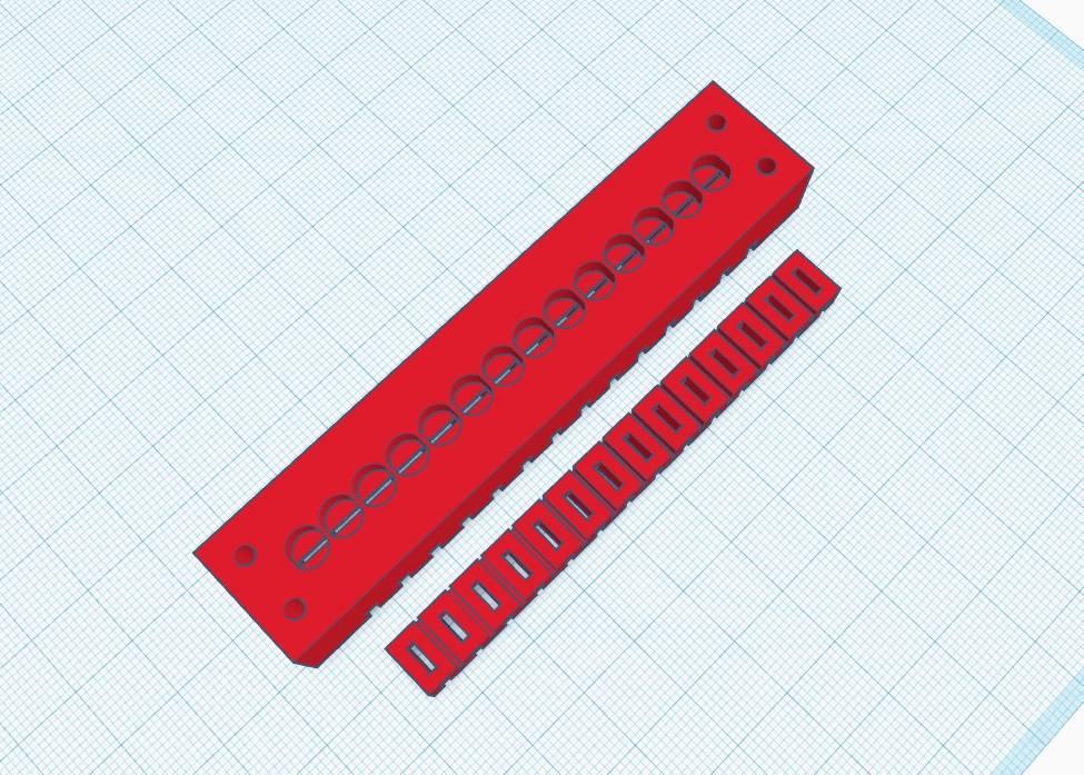
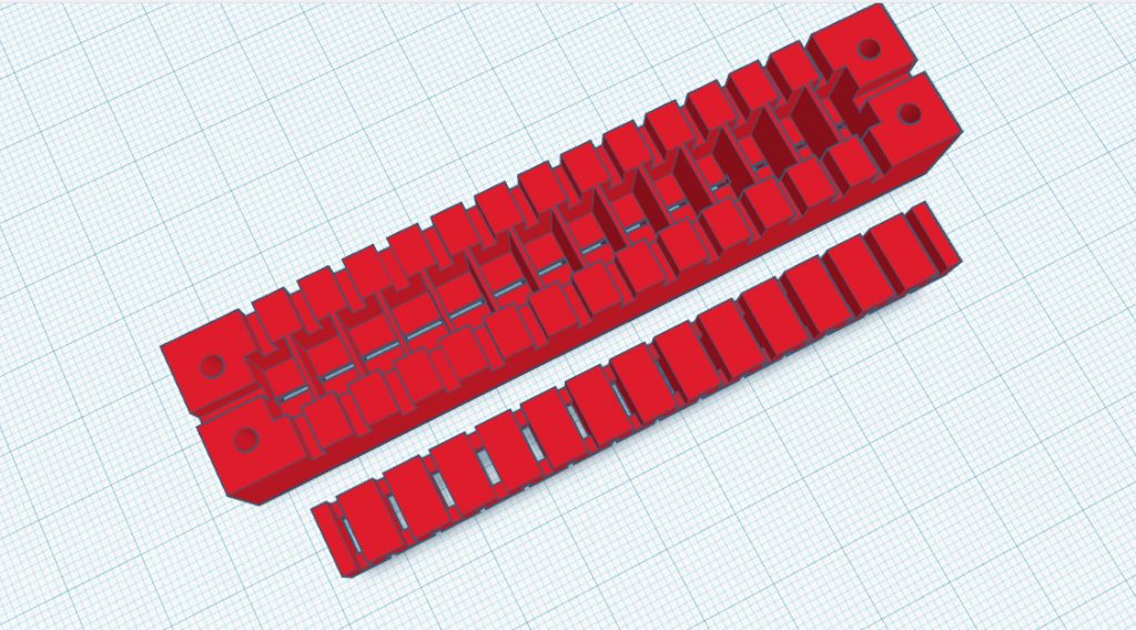
Throughout this Project, I’ve learnt many things like how to model objects in Tinkercad and make measurements properly, there are always failures in everything that I modeled before it works, and this is why 3D printing is a good prototype process where I printed it out and tested it to know if it work or not, if it doesnt, I will shave off some piece to see if it fits, if it does, I will make new measurements for the edited model.

I am really glad that this many piece worked well together and this was the biggest challenge.. since there are so many components working together (electrical and mechanical), even if one of the parts failed, it would not work as well as it is now. So I considered myself really lucky that the parts happened to work well even when there are misalignment everywhere.

Also, to have a Telephone case in the start and scale everything into the Telephone case was really a challenge especially at the start when I could not measure how big the internal was and could only make a guess and print some test print to try it out.

In this project, I realized that if I were to do a project that require multiple fields of knowledge like mechanical and electrical, It was better if I did not know how hard it will be, if I were to know that every part of the project will be something that I don’t know, I will be too afraid to jump into this project. I did something, realized that it doesn’t work and find solution to that single problem and proceed to work on the project and faced another problem, solving and learning one problem at a time lead me to the completion of the project.

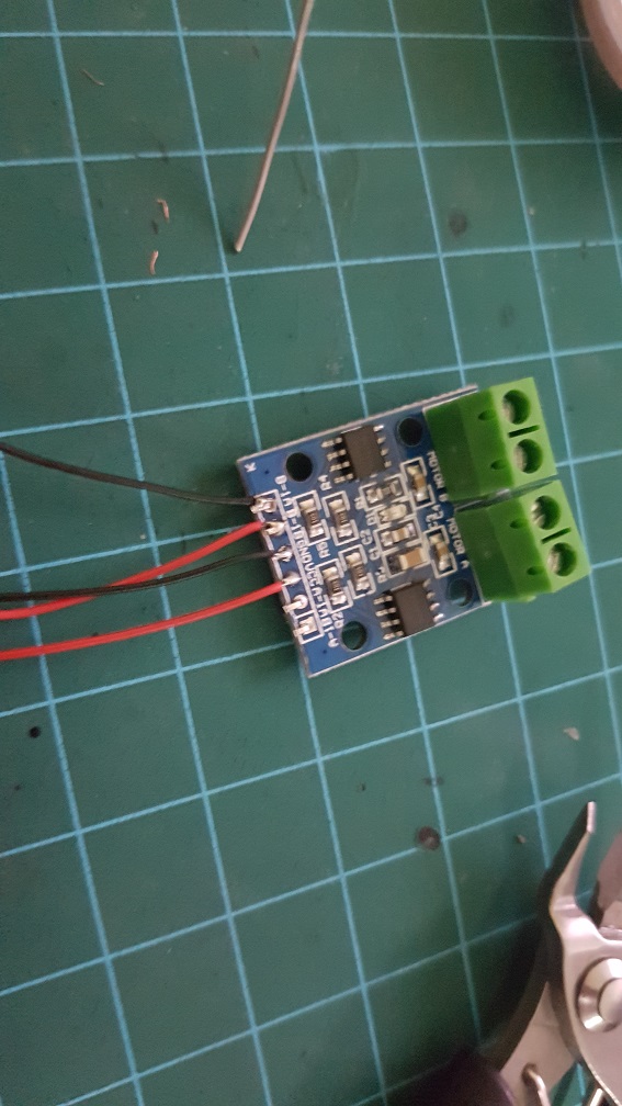
Now that I had completed the project and looking back. Obseleting Instrument is really a complicated project as a whole, but thinking about it, I am just putting many small system into one project- like using one laser diode and a photo resistor as a switch,  playing a tune when triggered, a physical button to sense if the phone was picked up, using a relay to control circuits of different voltage, running two DC motor at the same time and so on… Obseleting Instrument is just a collection of small systems, which I personally thinks was what made my journey of doing this project really interesting because I explored the basics of these components and learnt a whole lot through it.

Interactive Device Presentation – Unconventional Musical Instruments.

The file size of this presentation was too large to be uploaded so I’ve screen recorded the presentation and uploaded it to youtube.

I’ve chose to narrow down my scope to just Unconventional Musical Instruments mainly because it will be more interesting and fits the time limit nicely.

Device of the week 4 – GoBone

GoBone is a smart bone designed for the dogs and puppies and is available(currently out of stock) in Amazon at $200 currently and had raised $180k in the Kickstarter campaign in the past.

KickStarter Campaign

Amazon

Basically, it is a interactive automatic dog entertainer that rolls around like a remote-controlled car where the dog will chase it around like a cat chasing a mice. The wheel could also store treats that the dogs could eat from it and according to the maker, apparently the user could rub peanut butter over the shell for the dogs to lick… which.. seemed like a bad idea to me because think about running peanut butter all over the house and the mess it will make.

Looking at the process and timeline for developing this device seemed really doable even for our standard. since it started it’s development in an Arduino Uno, two DC motor with gear box that is available from china at around a dollars each which I happened to have the gearbox that I purchased to test my final project out but did not use it in the end.

so the connection to the phone and developing an app for it seemed quite hard for us, but the technology in the GoBone itself seemed relatively simple, receive inputs from the phone, turn MotorA and motorB in the same direction to move forward or backwards and turn both motor in different direction to spin the dog bone.

Although it is said that GoBone was designed for the dogs, I personally feel that it is still designed for humans to be lazy. And a $200 for a “smart” dogbone is rather expensive, but I can understand that pet owners are more willing to spend on their pet and hence they make a good target audience to begin with.


Interactive Devices Final Project: Obsoleting Instruments Process 2.

After the last post where I’m almost done with the laser reader and there are still improvements to be made to it, but I will focus on other component and will come back to make it sound nicer if I still have time, for now, I need to slowly build towards the completion of Obsoleting Instruments first… I will need to a way to feed the music sheet into the laser at a constant speed, so after some research and thinking, I could use DC motors with gear box that drives the music sheet through a belt

system, so, with that in mind, I purchased some special rubberbands and the belt driver thing, as well as some gears and shafts and the plastic DIY construction pieces to test it out.

First, Since I’ve got the Landline Telephone, i need to clear the little plastic pieces inside to make room for all my components, and I thought it would be a simple task, but MANNNNNN ITS SOOOO INTENSIVE(because i dont have a proper tool to do it)

Theres a Chinese saying “Small knife cuts huge tree” its a torture and yet quite satisfying for me.

its like the loding screen, I can see the final point when doing it, so the hole need to go 1 round. and my finger hurts.


This thing tortured me, I tortured it back. Fair Game.

Slowly, i manage to cut all protruding parts except for the two longest one as i still need to close the top back and secure it.

and then put the belt and the belt wheel to check the distance required to have the just right tension as too tight it will not spin well and too loose it will come off easily.

I tried placing then together so they could sandwich the music sheet, but this is too near and it wont work well

and if I use a gear system, I could do more of the thing, but still need to consider about it.

After I got the usable distance, I proceed to 3D modeling the parts that is required.

The initial concept of the belt system. I know its abit overkill but.. I dont know where will it fail so I decided to give the music sheet full support, also, this was measured according to the belt length, Motor dimensions, phone dimensions, laser dimensions and the music sheet dimension to make sure they all fits. The complex base plate is to enable me to insert the belt after assembly.


I placed some holes to save some material and reduce printing time.

Then split the base into two part so that I can work on half and combine them later, I think it woule be much easier for me this way.. (And I dont have to print 6 hours just for the base.


It worked really well, but there is only one problem, my top cover of the phone could not close as it is slanted, so I have to shift the whole plate to the back, or place the top belt about 40% inwards but I cant just shift both belt wheel as there will be the laser reader there. so…

I will settle on my 6th one for now, since this is only half of the system, I need to get my music sheet up first for me to test the speed of the motor with this system since if half doesn’t work, nothing can work.


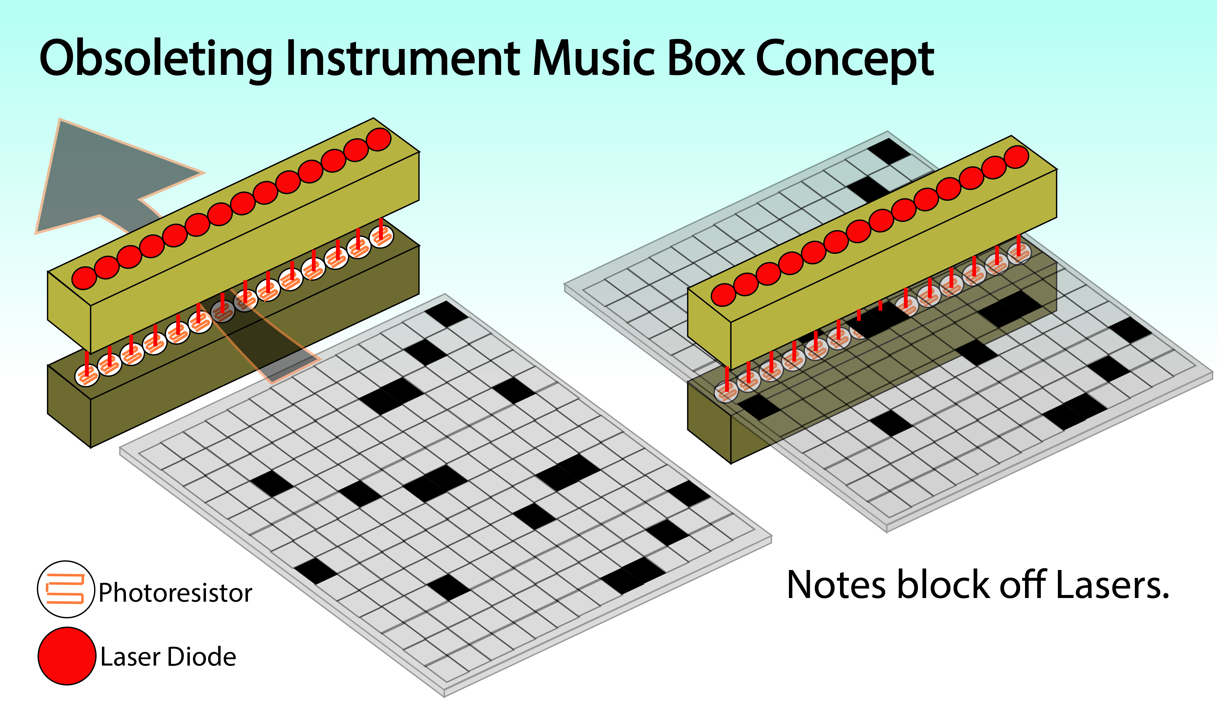
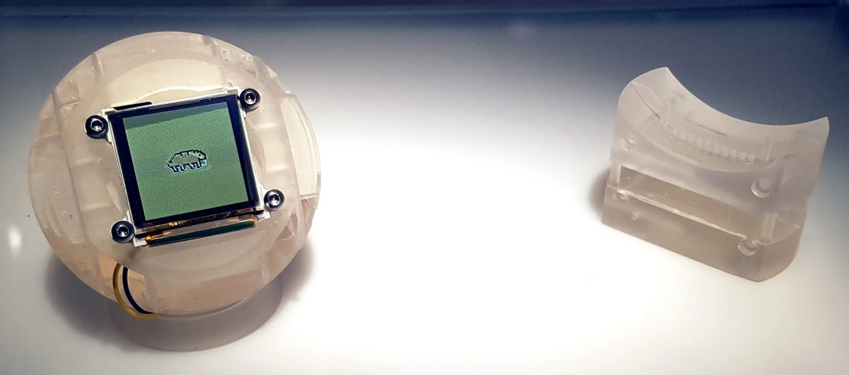
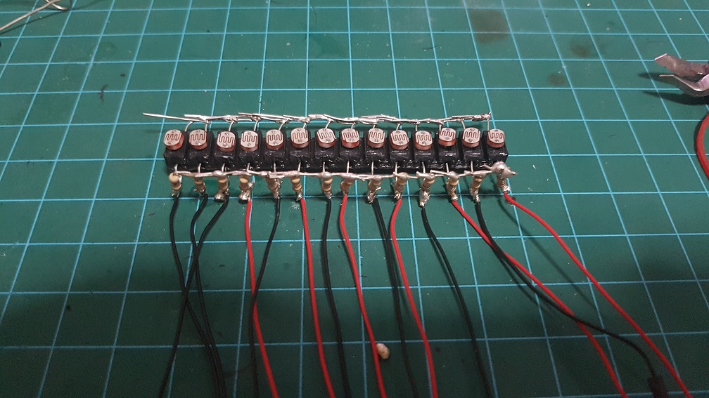
Pew Pew PEW. look at dem laZEERRRRR


I supposed it will work if i attach the motors to it. will upload another post once I’ve Progressed more.

Interactive Devices Final Project: Obsoleting Instruments Process 1.

After the Initial concept, I’ve 3D modeled the Laser mount and Photoresistor mount.

And after the Laser mount was done and working great, I went ahead to print the Photo Resistor mount.


It is designed to hold the photo resistor and allow the connector of each Photoresistor to be protruded out so that I could solder the circuit with the pull down resistor right on the module to remove the need for having a breadboard in the Telephone as the space will be limited in it, and i guess this will be the more efficient way of doing thing while making sure all connections are secured.

The soldering took some time to complete but luckily for me, I only need to do it once, or so I thought… (some part broke when I bring this to school so I did re-solder it again.)

I also purchased an old Landline Telephone on Carousell, I must say that Carousell is a wonderful thing.

In the end, the only part that could be reused is the phone’s body, the speaker/handle/hearing thing, the buttons and the telephone wire.


Meanwhile, I started to write the code on Arduino for the Laser and Photoresistor.

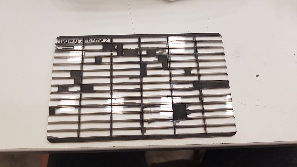
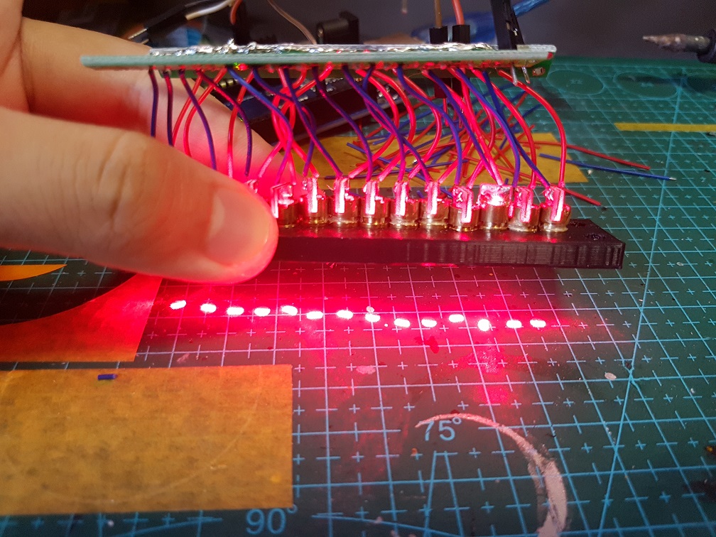
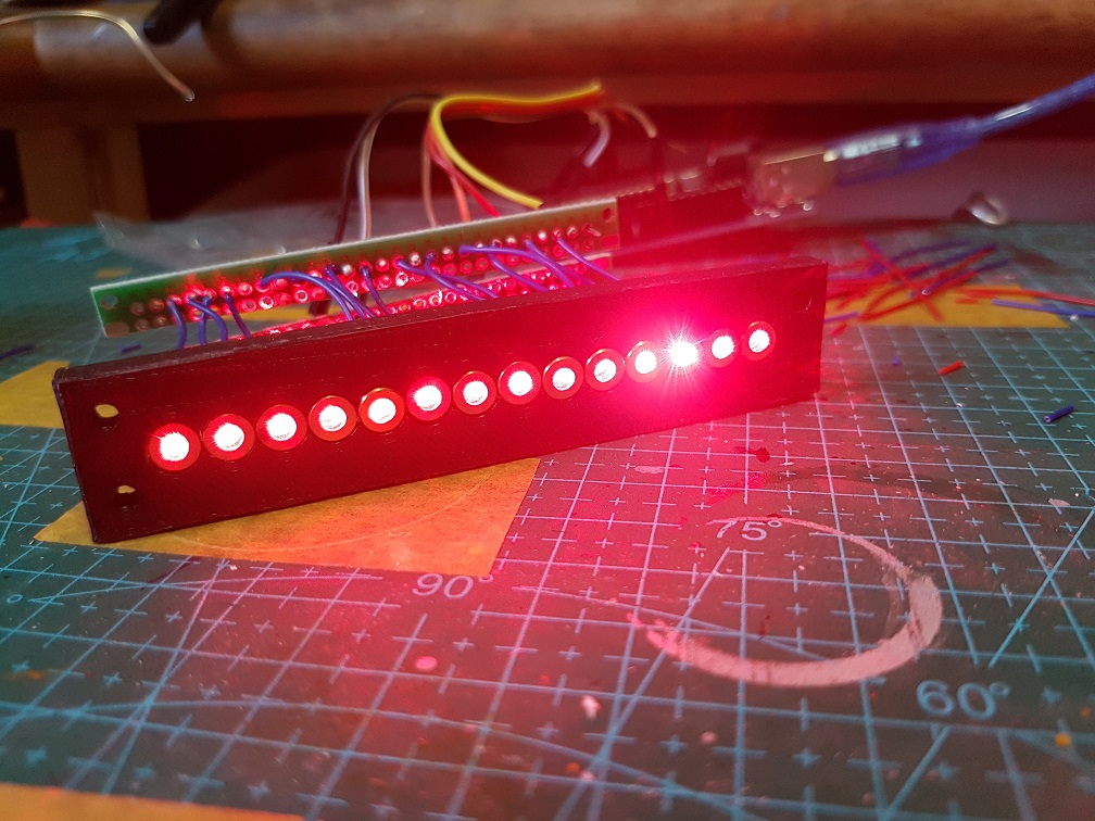
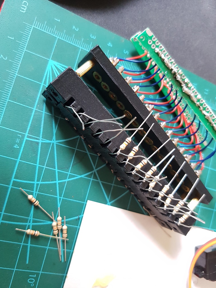
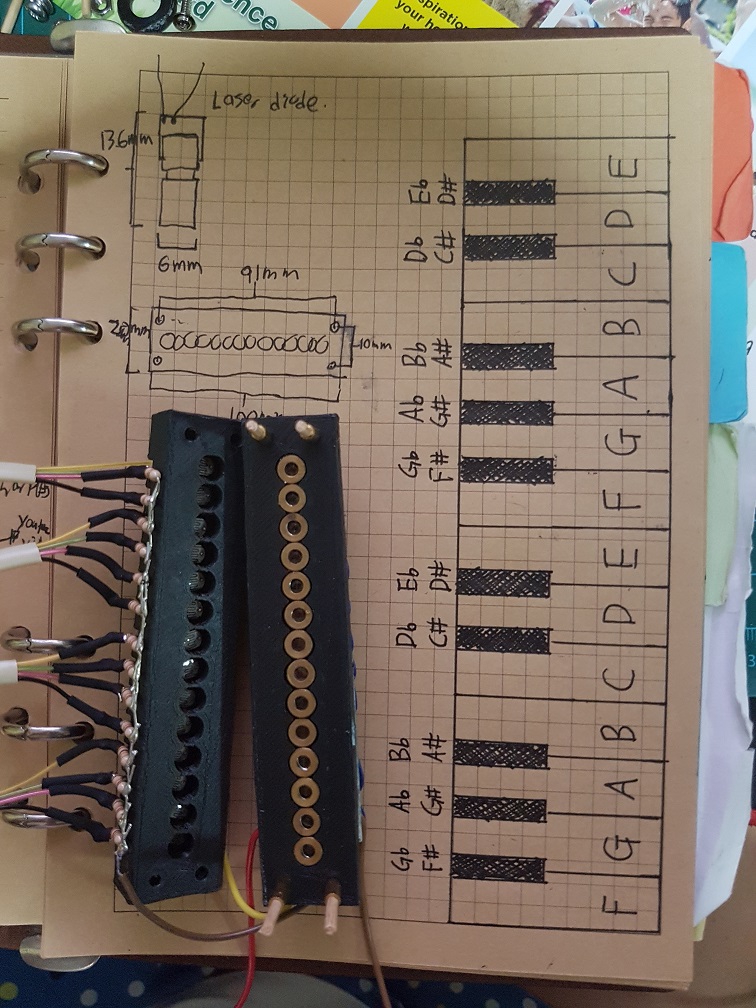
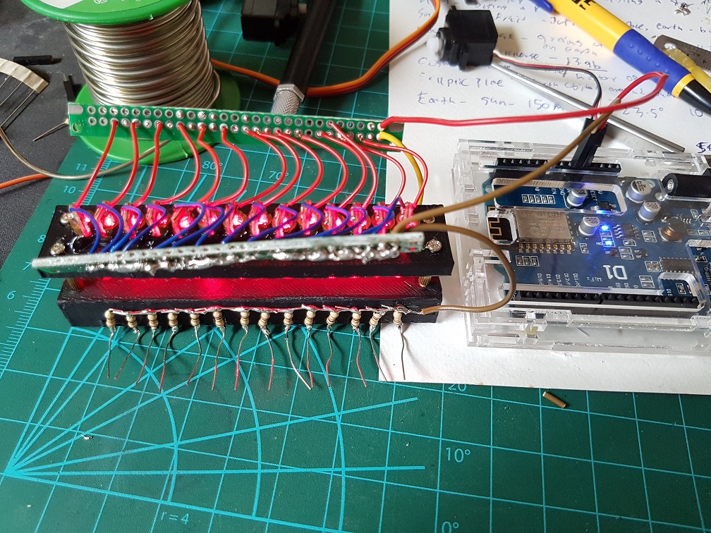
The value will be higher than 800 when the laser shine directly on the Photoresistor and lesser than 100 when blocked, so I can simply write if( value <= 400), play tone 1.


After some coding, this is my prototype for the music player part which is to be installed into the Landline Telephone.


Interactive Devices Final Project: Obsoleting Instruments Concept.

The speed of our advancing technology and the technology that is getting obsolete are on the same pace, 15 years ago, we were using Floppy Disks, 10 years ago, we were still using Compact Discs and the millennials now does not know what a Floppy Disk is. We still see CDs now but they are getting obsolete really soon as there are lesser devices playing them now.

Choosing of the Best Appliances.

For this project, I want to give new life to daily objects which are on the path of becoming obsolete by making them a musical instrument, there are many common appliances that are in this category and should be ancient in a few years time –

VCR
CRT TV( Cathode Ray Tube or also known as the old Fat TV)”
Remote Controllers
CD and all devices which plays them
MP3 Player
Old Gaming Console
Top Loading Washing Machine
Landline Telephone
Fax Machine
Public Payphones
Answering Machine
Slide Projector
Dial-up Modem
Basic Alarm System
GPS Units

Bold are appliances which are totally possible for this project since I want to make musical instrument and they naturally produces sound in their normal usage context.

Green are appliances which are Bold and their normal usage context have the interactions when the user use them, which make them exactly what I could use for INTERACTIVE DEVICES.

Image result for old gaming consoles

Since the signification of a Gaming Console is different for every individual, people plays different consoles and different game or not at all, it is difficult for me to create something that all the end user(during the End Of Year Show) will resonate with.

Image result for landline phone
The best of all will be the Landline Telephone as I am sure that most of the end user will have some interaction with it some point in their life and the basic function of a Landline Telephone is to receive a call or to make a call, this resulted in almost the same user interaction throughout the globe – making a call or when the Phone Ring = Pick up.


And the Instrument that I have in mind…

After my researches on musical instruments,
I’ve decided to use the musical box concept where the user could play music by inserting a sheet of musical notes and it will play music digitally.

This could be done by using a set of lasers and photo resistors to read the musical notes on a clear piece of plastic scrolling through the system.

There are 14 sets of Laser and Diodes due to the research I had done on music theory(not posted yet as it is still an ongoing research) whereas there are 8 notes in an octave but only 7 different notes in an octave C D E F G A B C, so by placing 2 octave next to each other, there will be 14 white keys C D E F G A B C D E F G A B as I chose to omit the last C so that it looks visually completed from the looks of piano keys.

And what about the black keys? since I don’t want to add in 10 keys for the major and minor (black), I could use a combination of the adjacent white key to produce the sound of a major and minor. For example if I want the C♯(D♭) key, I could have CD shaded at the same time to produce a C♯(D♭) sound.

Flow of usage

  1. The phone will look like a normal phone with an exception of a slot to insert the musical sheet into the system in the body of the phone.
  2. Nothing can be done when the phone does not ring or the user does not make a call.
  3. Scenario 1 – Phone Ring -> User pick up phone -> voice command user to insert the music sheet -> User insert music sheet -> the phone pull the music sheet -> User listen to the music.
  4. Scenario 2 – Phone does not ring -> User Pick up the phone -> User hear the *toot toot toot* tone of the land line phone -> User dial some number on the number pad -> User hear the tone of an outgoing call -> Voice command user to insert music sheet -> user insert music sheet -> phone pull the music sheet -> User listen to music.


Interactive Devices – Device of the week 3: Electric Paint Lamp Kit

Conductive paint had been here for some time and the application for seemed to be really a next level to interactive devices. This is an example of the usage of a conductive paint, Electric Paint Lamp Kit.

The Conductive Paint Lamp Kit is a simple product which springs from the novelty of Conductive Paint and what made it so special is that it is the most basic element of any circuits- forming connections between parts. With conductive paint, we could form electric circuits on any paintable surface which means the possibilities are only restricted by the surface and our imagination, In the Lamp Kit, it uses only simple Light up board, some printed paper and Conductive Paint in different combination to form 3 different variation of lamp, if we were to use other modules of sensors or output, I am sure that it would be really fun to play with these.

Like for example, if we were to use projections on top of the conductive paint on a wall, it would be like so.

This is definitely an interesting project to be done and would be possible for us to complete with our current knowledge after some explorations.

Another project which latches on the idea on a set of more advanced conductive paint is this, the Electroluminescent (EL) Device.

The Electroluminescent Strips could be created by using a few layers of different paints.

and how to create that exactly could be found here:

In Conclusion

The element of interaction within the Lamp kit not only acts like a Lamp, it is also a DIY kit which the user would participate in making it into a final product which gives the user a sense of involvement and increase their liking on the product as it was made by them. Maybe I could incorporate this idea of involvement into my final project where the users could create something that runs in the system which I created.

Also, Conductive Paint seemed really interesting to play with it and the potential of it is endless, we should be able to see better Conductive Paint and Conductive Paint Projects in the market really soon and I probably will purchase one to play with and maybe make it into a project or something.


Interactive Devices – Research 2: Musical Instruments.

Unconventional Musical Instruments

So, Lets go back to the basis of music… What is music?

Music are basically sound organised in time.

so to break it apart, any thing that produce sound in a timely manner could produce music. right.

and if goes further, sound is vibrations through a medium like gas(Air), liquid(Water) or solid(Bones)

and if we reverse the broken parts back up, anything that vibrates in a timely manner could potentially generate music. YEAH~ a ruler could vibrate, so a ruler is a potentially musical instrument.

As with my previous research about motors, Stepper vibrate more than Servo, so a Stepper is a louder musical instrument than a Servo.

of course, they should not be this loud so they were placed on a table and the vibration will be transferred to the table and it will resonate which amplifies the volume of the sound as the table have larger surface area.

Old floppy disk reader contains motor inside, with programming, they could produce music too:


Musical box  instruments.

This is basically the introduction of a music box, I think Music boxes are wonderful instruments that seems really magical considering that they could play music almost automatically minus the winding part at around 200 years ago where electricity were not even used as modern context(not in the sense that Egypt used “Batteries” thousand of years ago.).


Remember the video which Prof Demers showed us during lesson, the Marble Machine by Martin Molin?Image result for marble machine

I was fascinated and really impressed with the amount of calculations, engineering and mechanical effort used to build just one of these machine. This is a manual musical instrument that the skill of the artist really contributed to the overall work of this piece, imagine if I were to play it, it will definitely not sound like the original.

And I will talk more about the inspiration or the predecessor of The Marble Machine, “The Eighth Wonder Of the World” which is an Orchestrion that incorporate 3 violins in it. This too, the engineering effort within it is astonishing!

The 3 violins were used due to the mechanical aspect of it, since violins have 3 strings, it would made more sense to use 3 violins one string each than to create a complex mechanism that play all 3 strings on one violin.


Futuristic spin on Traditional Instrument

The classic instruments are awesome with limitation, This is why people are programming advancement into classical instruments.

Lets take a the simplified evolution of piano starting with the oldest piano in existence(around 330 years old) for example.

Related image

after a lot of version and variations that sound slightly different and with some improvements and then came the Electric piano in late 1920(90+ years old) which is an electro-mechanical instrument.

Image result for Neo-Bechstein electric grand piano
Piano Eléctrico Wurlitzer, modelo 200A.

and then after many versions of improvements, the more recent evolution of the traditional piano is the roli seaboard rise which uses sensor which then produce sound electrically, the interfaces still follow the traditional piano, however the sound produce and the means of producing the sound was nothing like the piano any more.


In Conclusion

In these researches of unconventional instruments, music box and the evolution of old instruments, I could see that we could use anything which could produce sound to be the base of a musical instrument, We could revise a traditional instrument like roli seaboard rise, we could build a system that uses old unrelated objects and make them an instruments like the stepper motor music,  we could possibly use a system that plays existing musical instruments like “The Eighth Wonder Of the World

There are no right and wrong ways in making music, the only problem is is it audible?


Interactive Devices – HUMAN+ Reflection and critics.

Through the exhibition, it kept coming to me that human was always seeking to be a better version of ourselves and it’s only recent in human history that we are able to breakthrough some technological barriers which finally make some progress in augmenting human’s physical and biological to make improvements. Since I personally think that morality is just a concept which is generally accepted by the culture, there should be no right and wrong in the idea of augmenting human, even on genetically modifying a baby since culture will change depending on time and location, genetically modification might be the norm in 20 years time.

The work that I am most interested in was the Tardigotchi.

Tardigotchi is a work done by SWAMP collaboration with Tiago Rorke.

The basic idea of Tardigotchi is to have two pet, one tardigrade and an digital avatar of the tardigrade. A tardigrade is an eight legged water animal which could live in the harshest environment on earth and even outerspace, I remember watching a documentary years ago about astronaut sending tardigrate into the space to test if they can survive the vacuum and radiation. Not only the tardigrate survived, they lived happily and reproduced in space and this was the reason that I really love this project and is sure that there is a real tardigrate inside of the sphere.

Another reason that I really love this work as I had thought about doing a project last year for Interactive 2 which reflect on my childhood where we keep tamagotchi as pet and I wanted to recreate a project similar to tamagotchi but on a bigger scale, like a projection at ADM lounge and we will have an ADM pet. So this project resonate with me a lot personally, just by seeing this project lying in Human+ exhibition, I knew i will write about this instantly.

This is the Tardigotchi in Dublin Human+ exhibition and it seems so much nicer then the rapid prototyped model here in Singapore.

Interactive Devices – Device of the week 2: Boscloner

There are a spectrum of devices that serve its purpose to the user, devices that save people’s life, make live easier, and there are devices that would be a disaster when fall into the hand of the evildoer, Ladies and Gentlemen, today I present to you the latter, *Drumroll* THEEE BooosssCLONER!

The Boscloner is an RFID capture and cloning machine that will clone the proximity card(Read: NTU Matriculation card & Hall’s Key fobs ) wirelessly and send a notification to the user’s phone when the cloning process is done and the user could use the cloned card just like the victim card to access into restricted areas. Just how wicked is that! Boscloner is an open source project that they also sells the its components for enthusiasts to build them from ground up!

Heres a video that explains how it work:

Amazing right!!!

Boscloner is an advance system that could clone the RFID proximity card just by being near the target, there are less complex system that could duplicate our matriculation card if we scan the card physically and write it into the empty proximity card and it could be built using Arduino.

Heres one video tutorial of Arduino proximity card cloner.

The basic idea here is to use RFID (Radio Frequency Identification) tag(card) that consist of an integrated circuit and antenna built into the tag:

Image result for RFID card cut up

and having a RFID system that could read or write the information stored in the tag. Image result for arduino RFID

as simple as it would sound, there are a multitude of applications for it, we could not only open doors to our class room, the industries had been using for task like inventory management, counterfeiting prevention, race timing tracking and Library system. Since RFID is a cheap and adaptive system, it could be applied to countless of projects, what if we use RFID system as an installation piece where every visitor was given a unique RFID tag and upon going close to the installation, it reacted differently to every visitor? It may be really amusing as a visitor.