Continue from my part 4 of this project updates, This is the final part which leads to the completion and is rather long as many things from getting the power supply, modelling, testing, painting, assembling to coding had been done in the past 2 weeks.
First, the final video of The Curious & Timid Turtle.
And then, into the process….
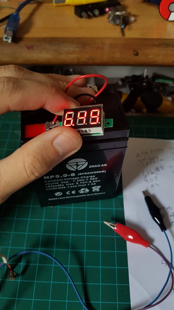
NEW POWER SUPPLY!!!
At the end of last post, I was waiting for the power supply to reach and it did during these 2 weeks so I’ve tested it out, The one that I bought is a AC-DC converter at 6V 20A when all I needed was 6V 8A, i decided to buy the higher Amp one just if i need more amp in the future, and I could also share the supply to my Interactive device project during the End of sem show.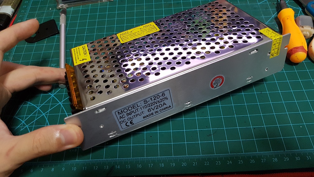 I did some wiring afterwards.
 And after the wiring, I did power test, it could easily run 8 servos simultaneously with nothing overheating. which is a great news for me!
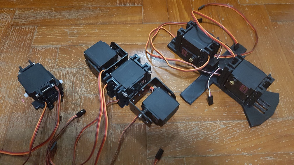
NEW LEVER SYSTEM FOR THE LEGS!!
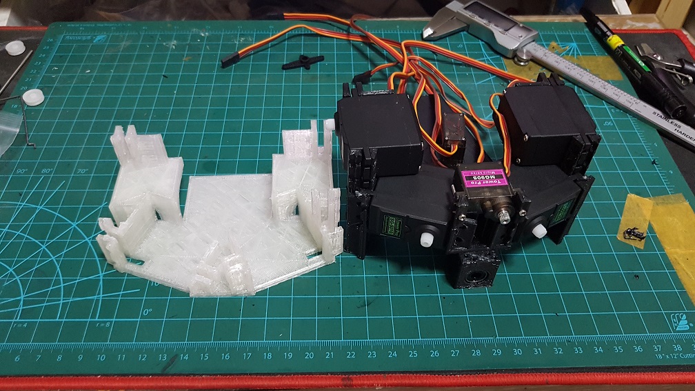
Since the last post that I’ve decided to change the system in the legs to save space and shorten the overall length by stacking a smaller MG90S on the MG966R to act as a lever system to pull control the legs.
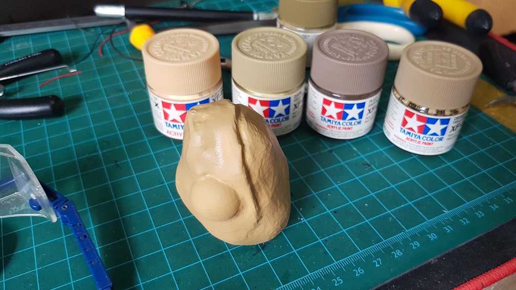
 After testing this system out and seemed to be working, I merged it with the turtle leg that I’ve modeled in Zbrush, I don’t know about Zbrush before this project and it tool a long time just to model the shell, the legs and the feet.
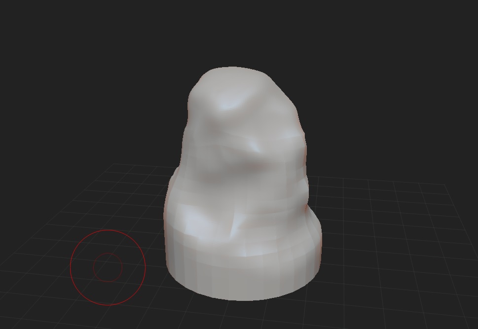
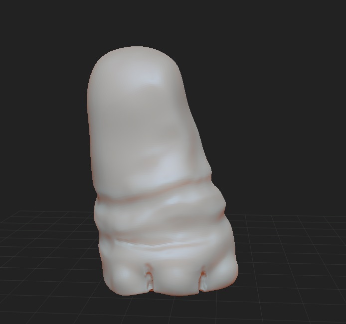
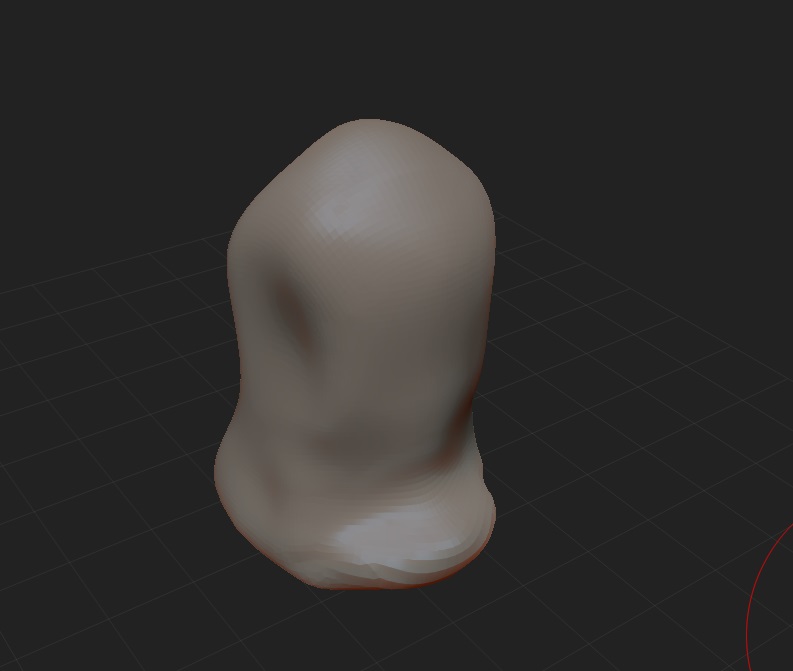
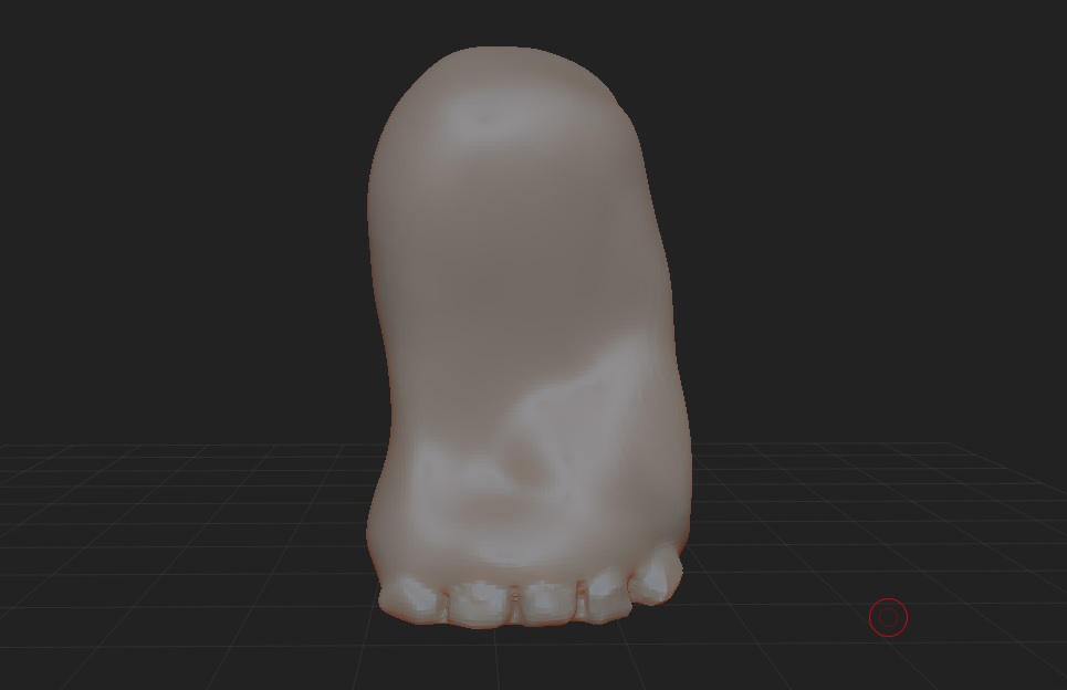
I merged the leg with the previous test “rod-like” leg because I’ve already gotten the dimension in there so i just need to scale the Zbrush modeled leg accordingly to fit the “rod-like” leg.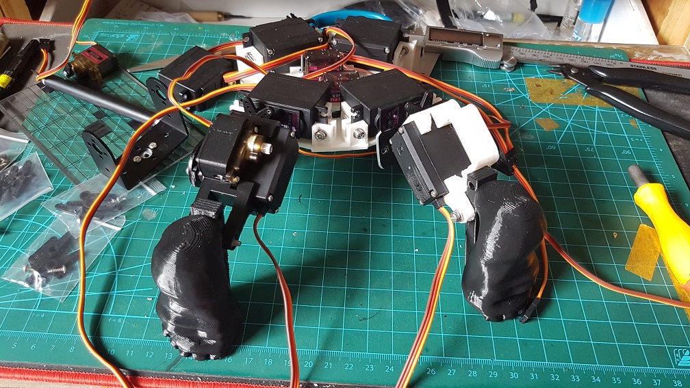
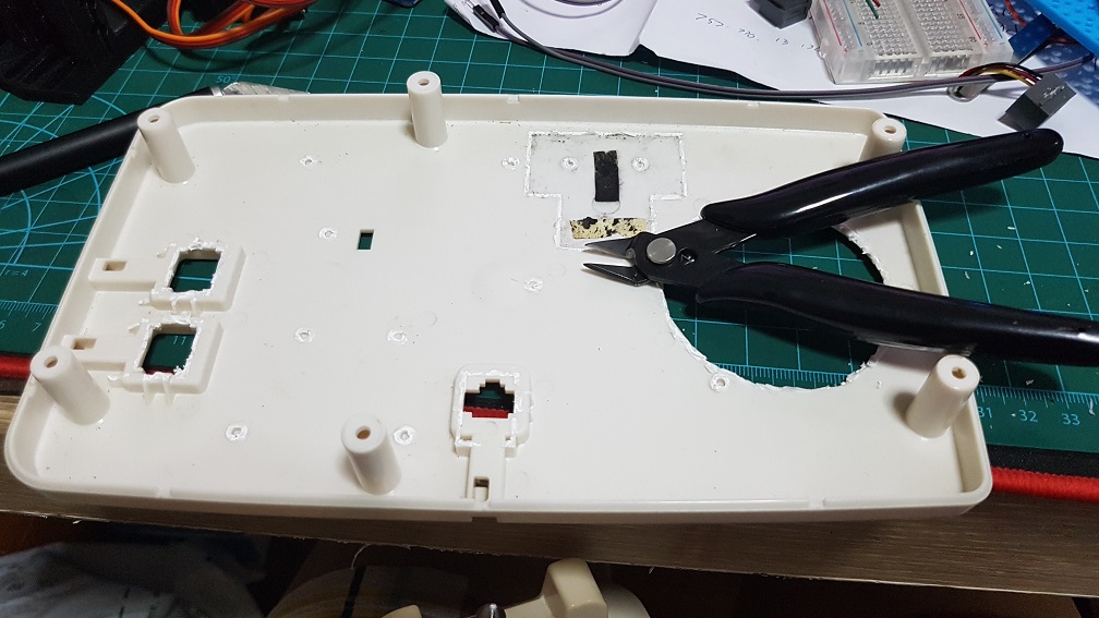
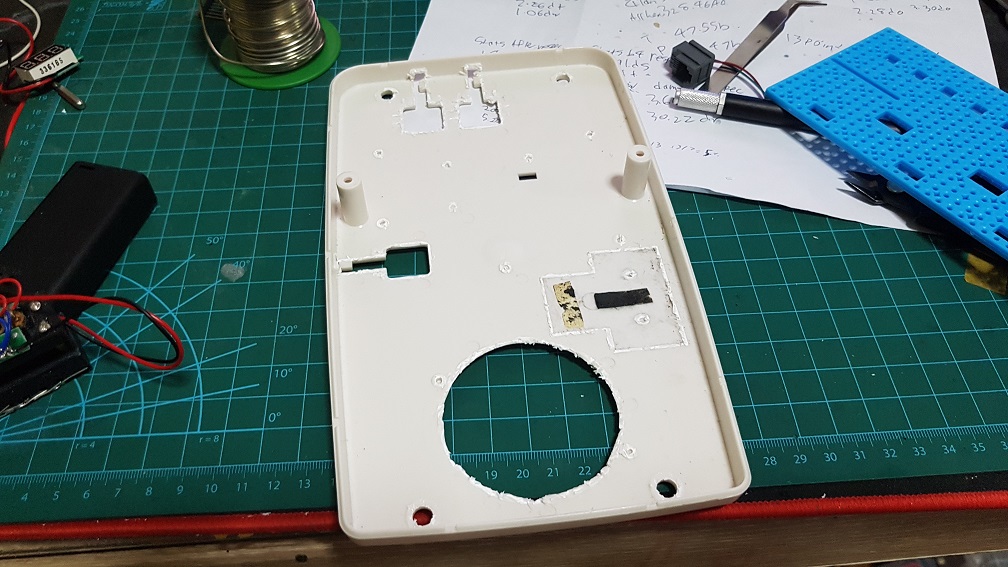
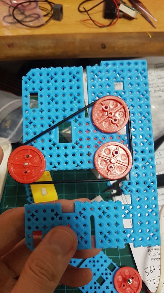
changing of the entire base layout to reduce size and increase EFFICIENCY for the back legs.
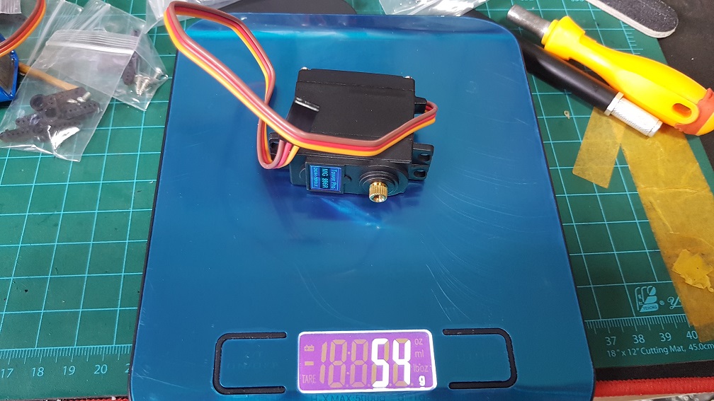
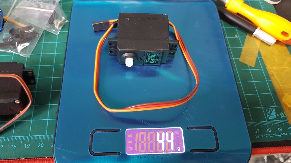
At this point, I was wondering if I should change the MG966R(metal gears) into SG-5010(plastic gears) due to weight issue I might face later after adding the shell and so on, so I weigh the motors and decided that I should change the back leg to SG5010(but I changed it back to MG966R one day before submission due to the internal gears got loose in SG5010)
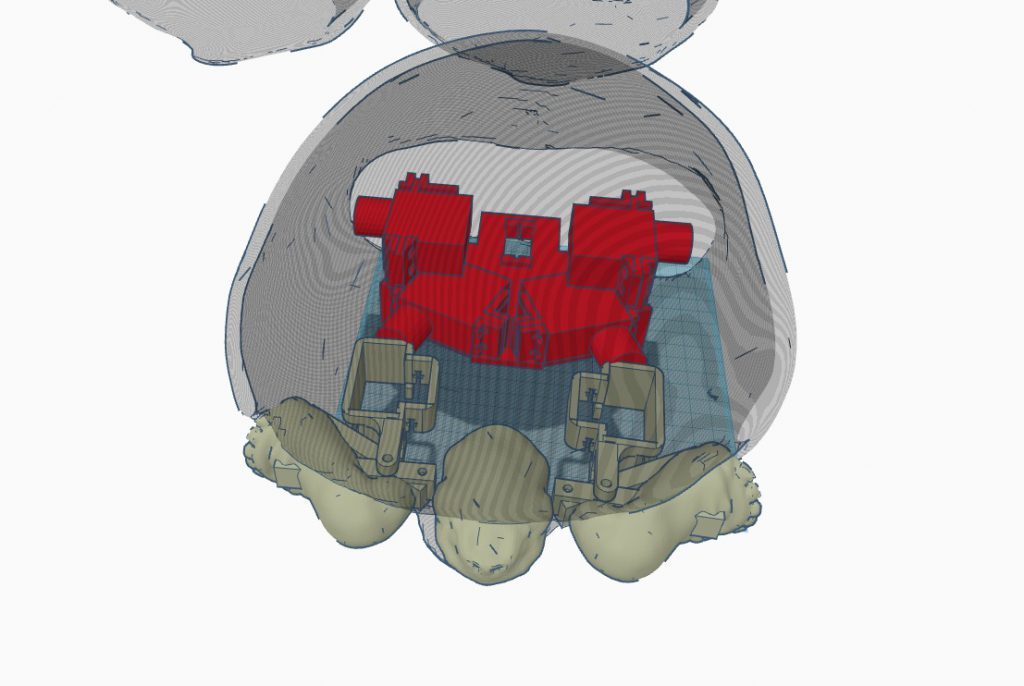
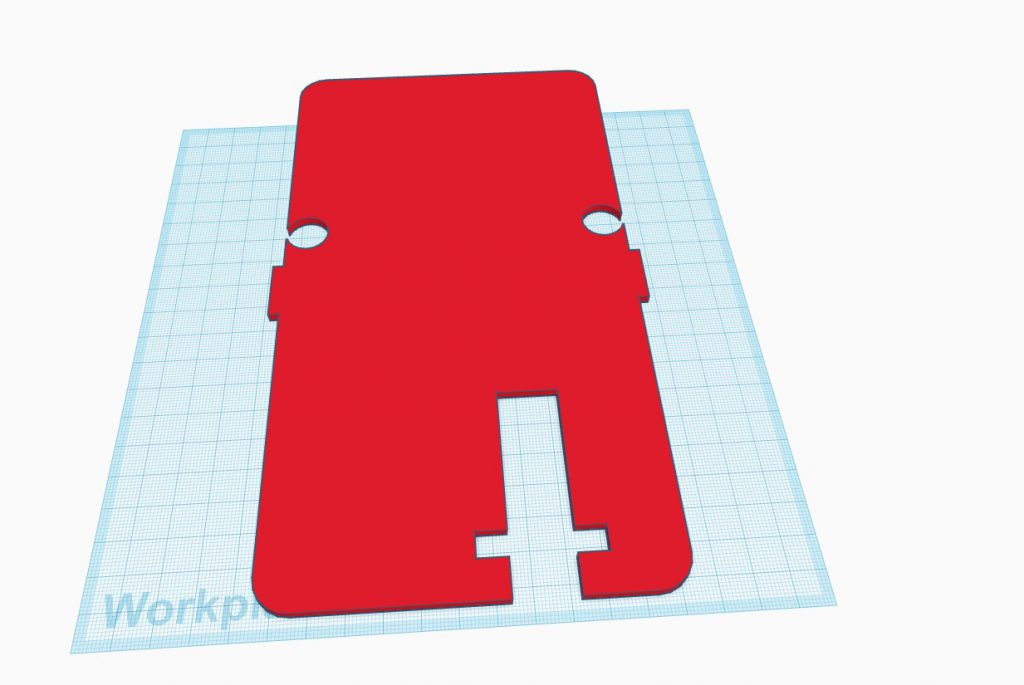
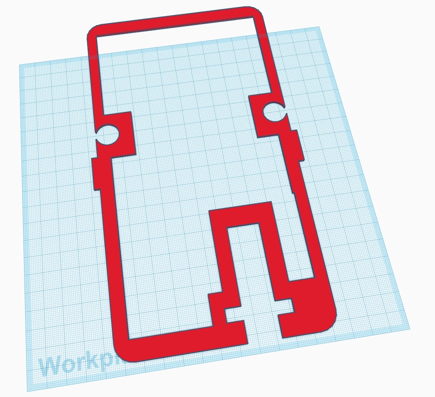
Major changes were made for whole layout of the base due to various reasons – the backleg will move differently from the front and since my project is basically a turtle with round shell instead of a flat one, it made more sense to use a smaller but higher layout rather than a flatter and wider one to make use of all the space within the shell.
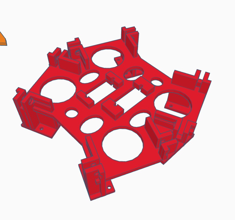
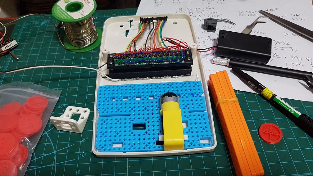
 This was quite the final base before I added the mount for the small backleg servo and the servo driver mount which will be attached it using screws.
Zbrush Modelling Nightmare Funfair
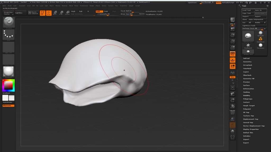
Since my Zbrush was cracked, it crash rather often and I did the same thing over and over if I forgot to save frequently and hence it took quite long to model anything, but well~~
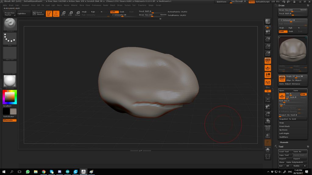
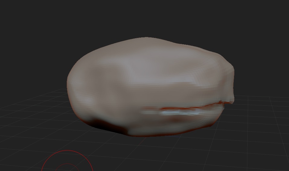
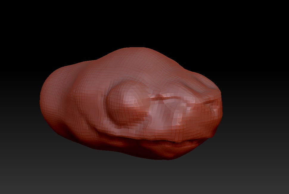
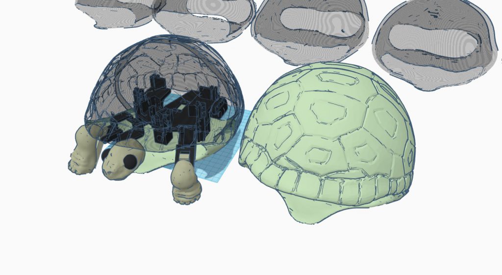
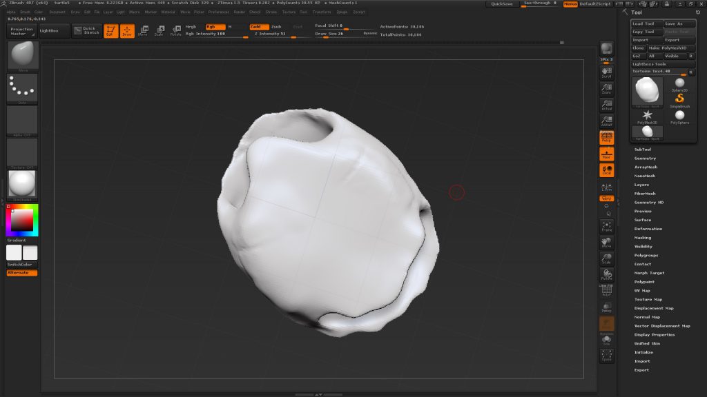
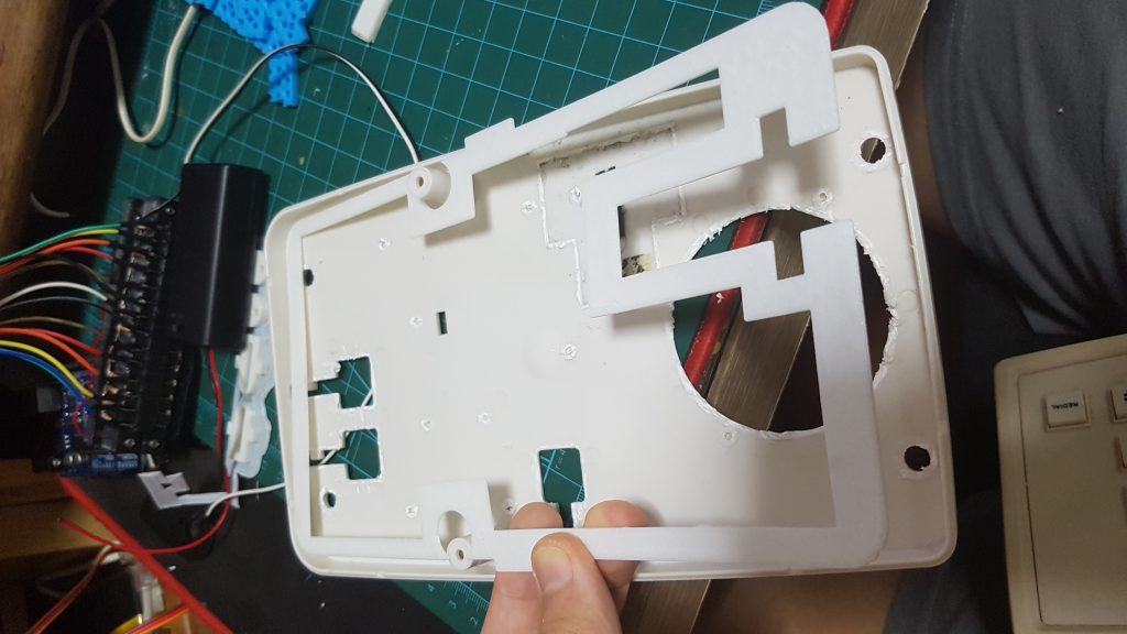
As for the shell… it took so much time and crashes to get it right, because the shell cannot be too thin(unable to print later) and cant be too thick (too heavy) and I cant find a function that could allow me to see the thickness (like reduce opacity of the material to see through), so everytime to check the thickness, I have to export into STL, and import into Tinkercad to check the thickness.
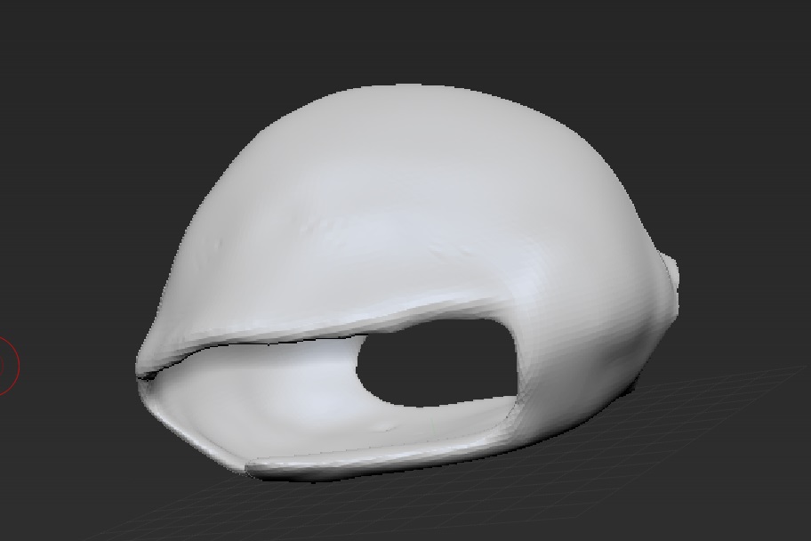
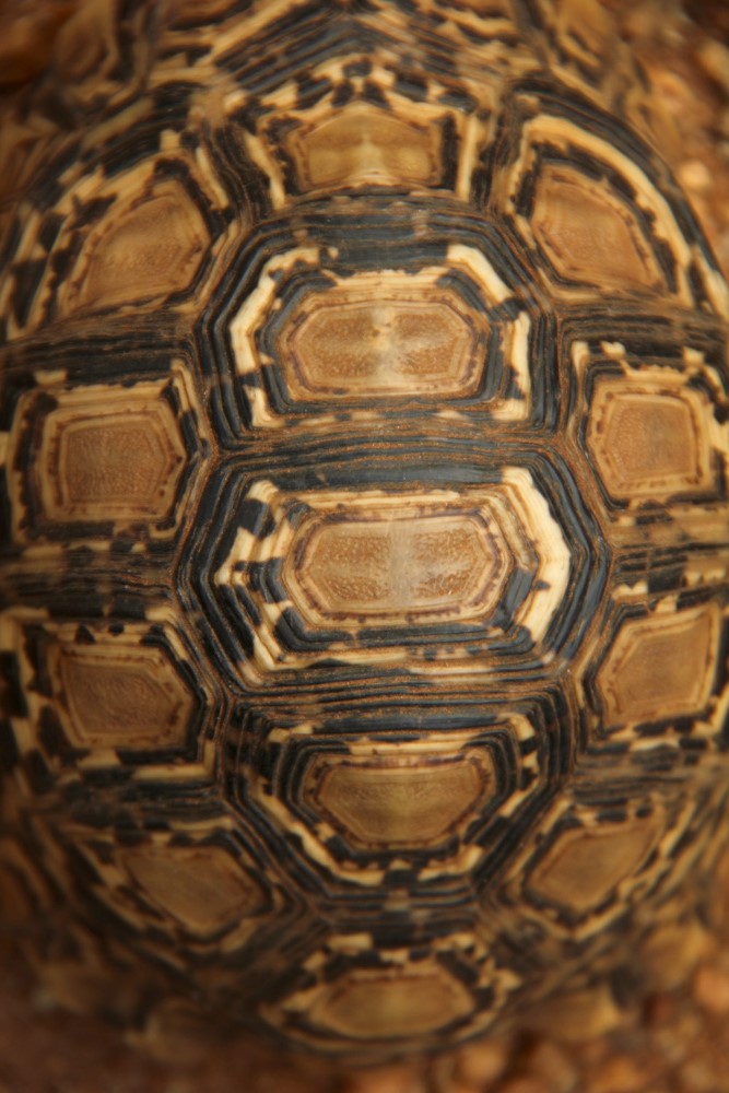

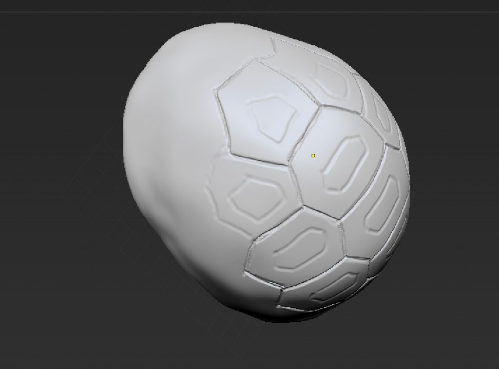
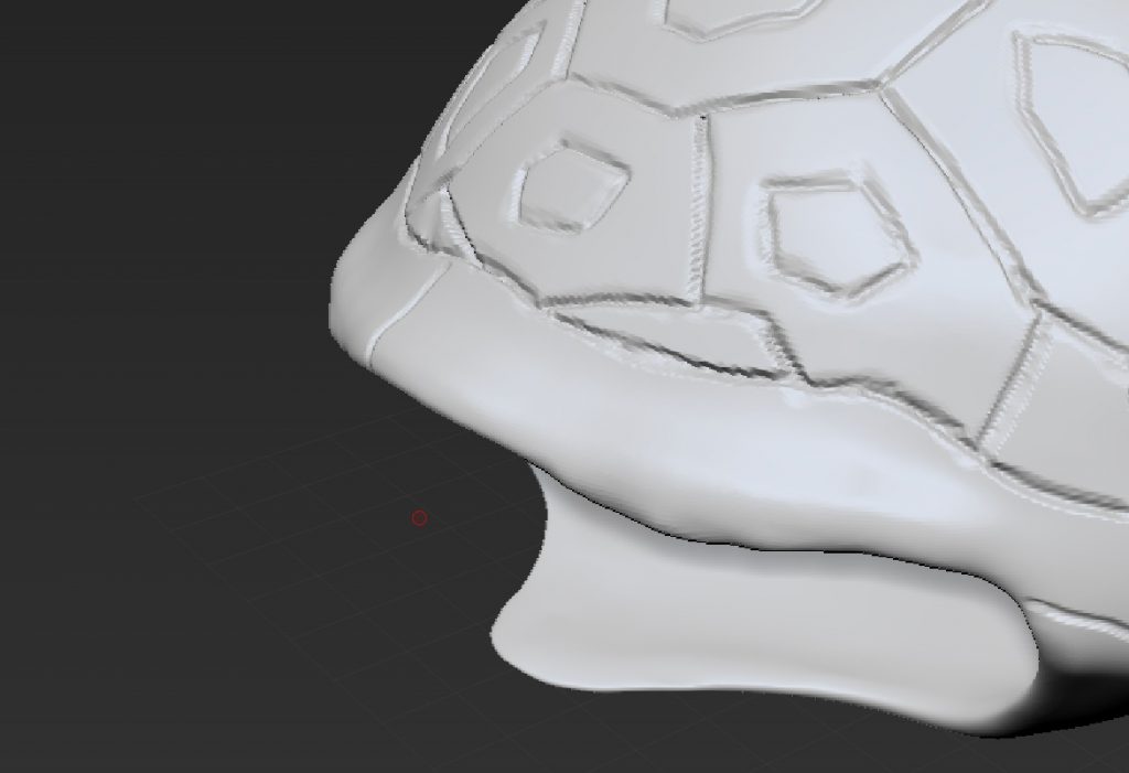
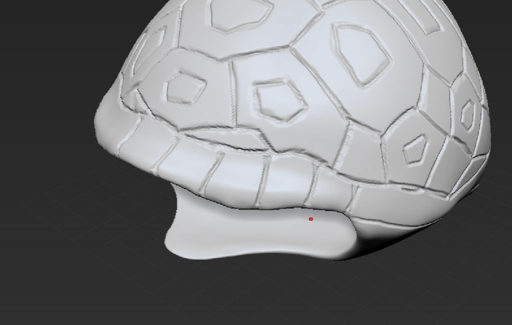
Everytime I made major changes to the shell, I’ll have to import to Tinkercad to check the thickness and shape.
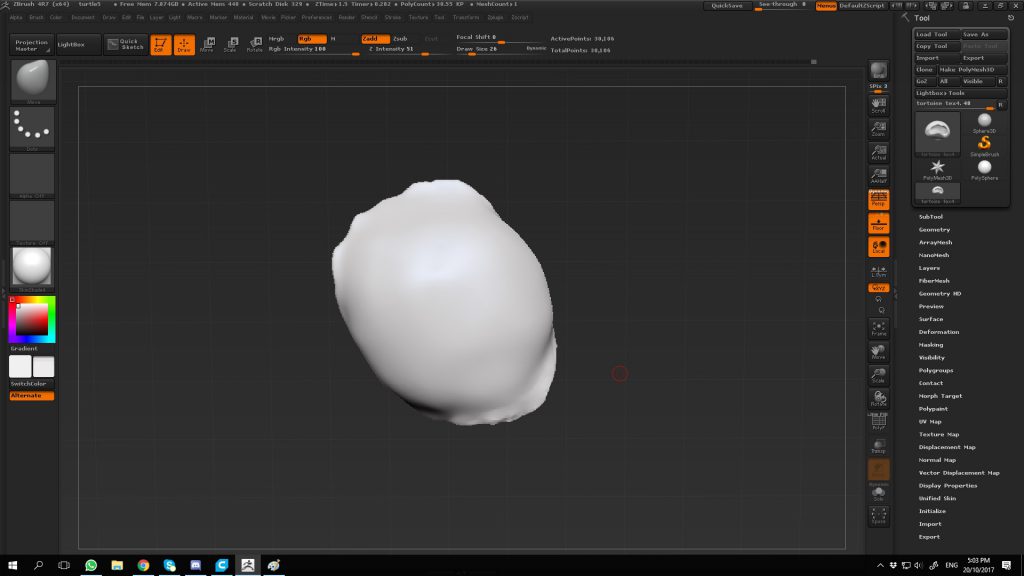
The model appear
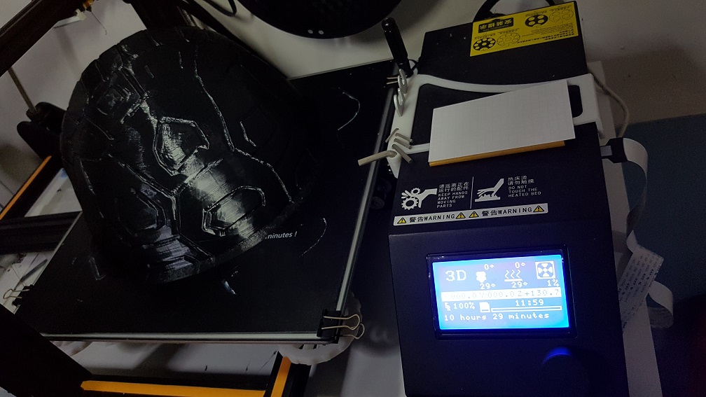
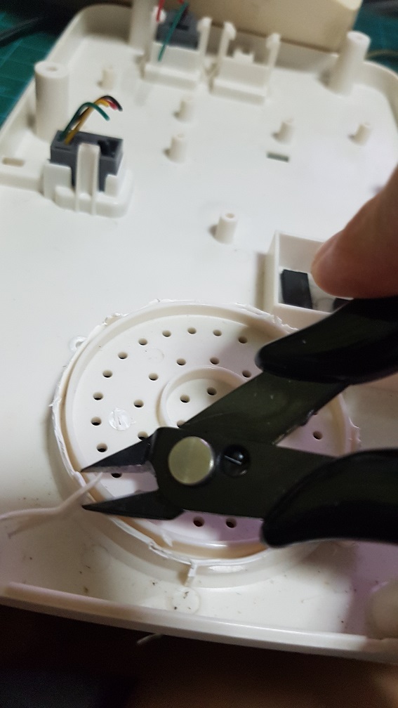
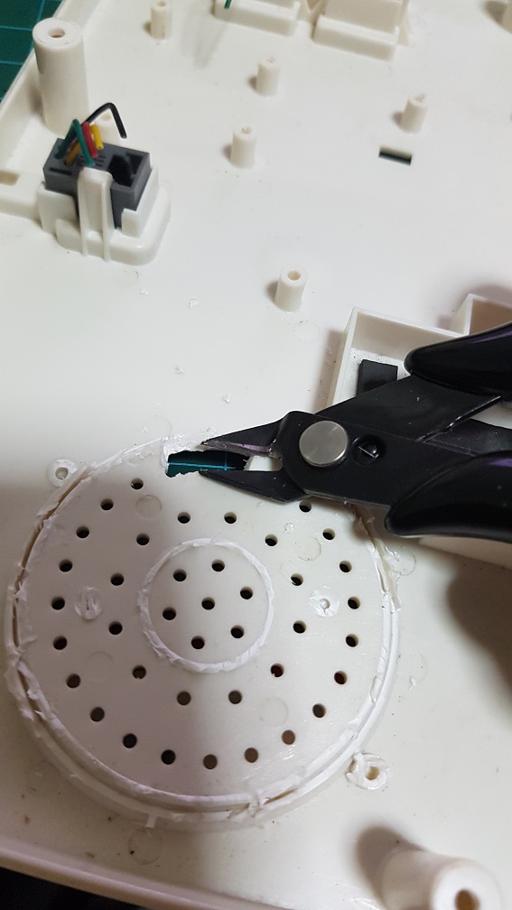
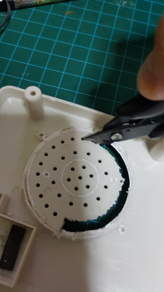
 Nothing is more satisfying in removing the support in one whole chunk(I did alot of cutting before this video so I can pluck out in one piece.)
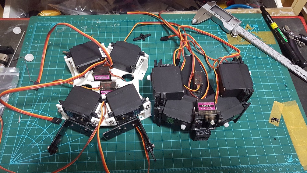

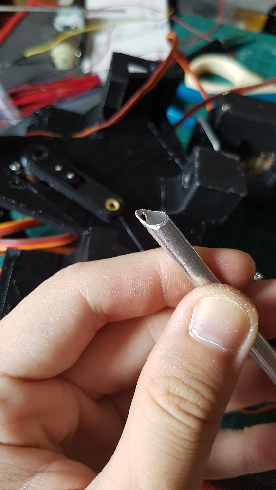
 this is the liner slider an an aluminium rod for the head system.
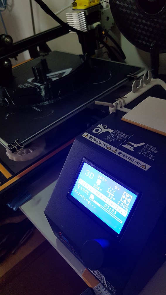
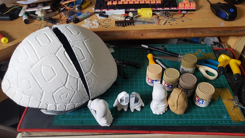
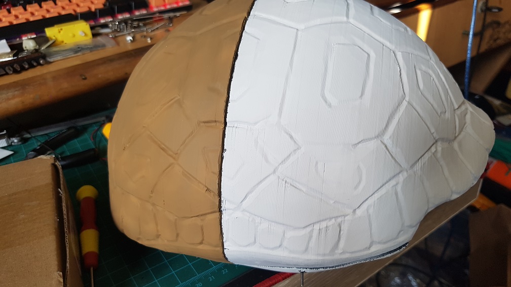
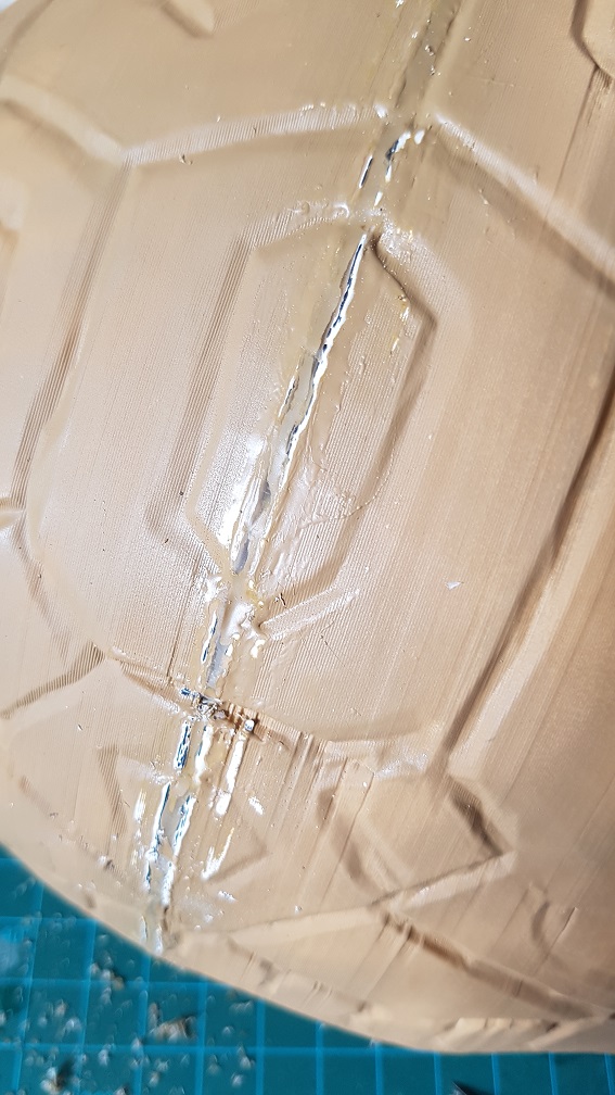
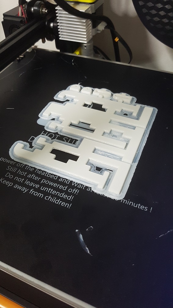
Printing for the base shell:
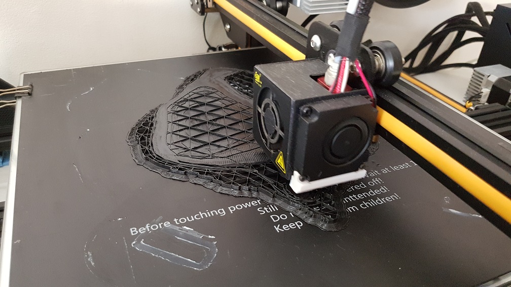
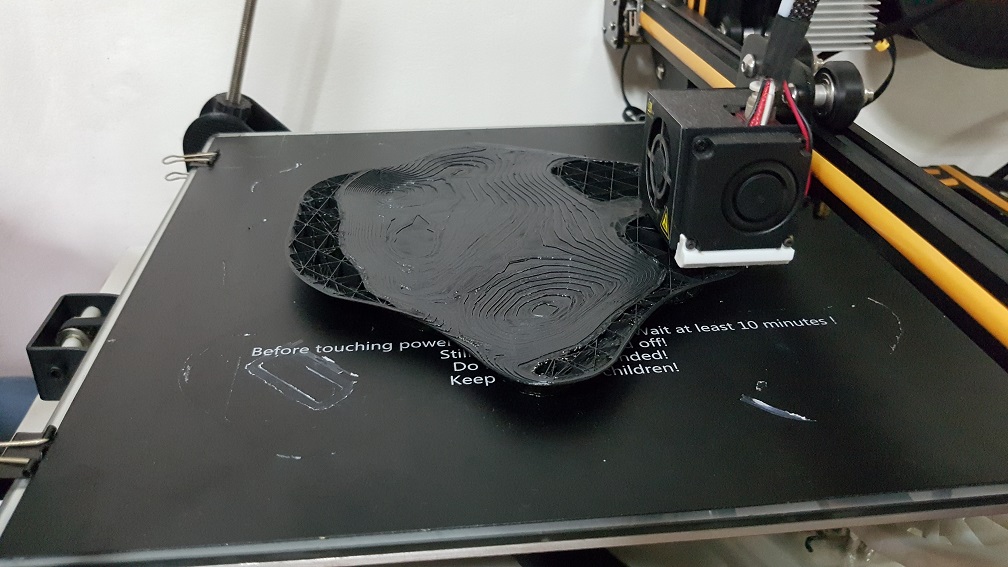
Printing for the top shell:

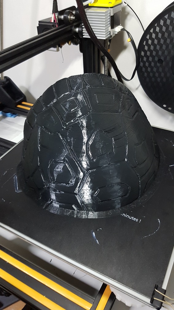
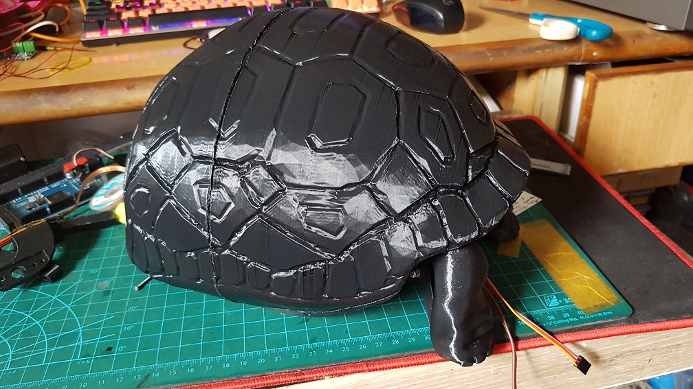
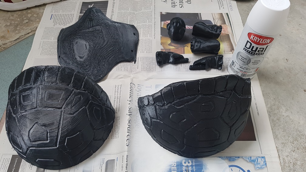
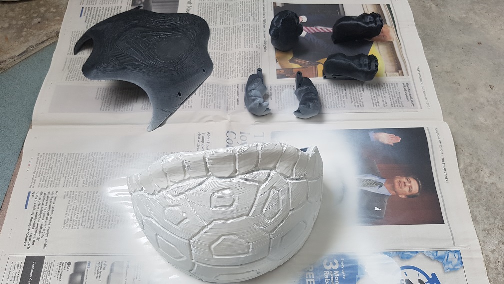
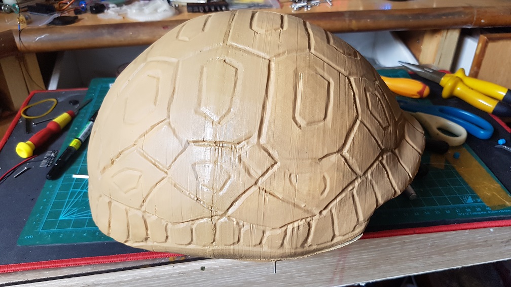
And then the finishing(PART1)of the model.
The Final mechanism of the turtle
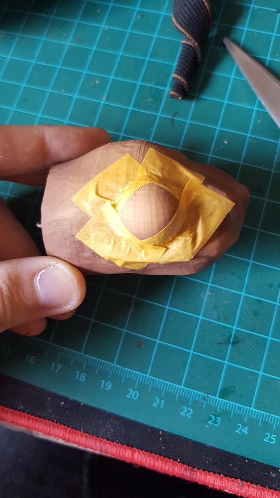
 testing out of the head slider and to mark the length I need it to move and cut.
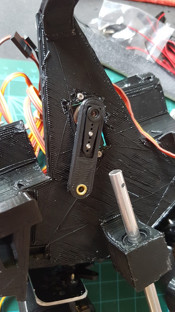
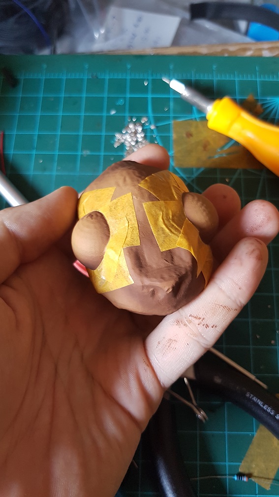
 The mechanism to slide the head that I will use after cutting the rod to almost the size I need.
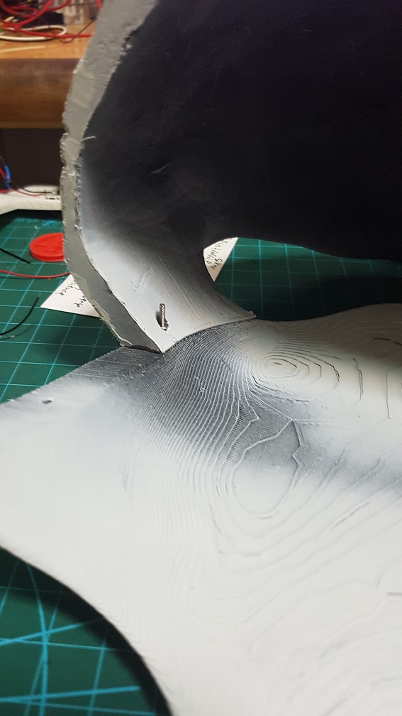
 this is the final mechanism for the head after I printed a small piece to prevent the wire from tilting too much when pushing the rod.
 the head could be push and pull out nicely even before adding the string to control the tilt of the head.
 metal rod were epoxyed into the head to tie the elastic thread to control the tile of the head.
 and a elastic thread was added to counter the tension created by the elastic thread to turn the head
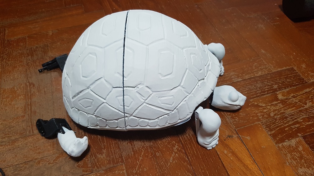
And then the finishing(PART2)of the model.
 The final test of the turtle before I finally started coding it. The head uses elastic thread because it will go forward and retract, since I dont want anything to be loose and might interfere with the shoulder servo motor, I decided to use elastic thread so that the thread wont be loose when the head is retracted.
 This is the almost completed sequence of action,the turtle’s movement is quite restricted due to the shell and the back leg is unable to push the turtle forward because of the shell’s restriction as well as the weaker servo(MG90S) which is responsible for the forward and backward thrust, while the MG966R is strong enough to lift the turtle up, so the turtle could do movements up and down but not walk.
After this, I added a few lines of code to substitute the button pressed with sound sensor to make the turtle more intractable and a few more actions that made it more timid looking (head peeking out to check the environment before the whole body come out.)
In conclusion:
Overall, I really liked this project although I kind of regretted trying to make a turtle during the process because the shell is giving a lot of layout and movability problem made me kept thinking that if I were to make something without shell, it will be so much easier, but the reason that I first wanted to make a turtle is the best is because the shell naturally hide all components that break the user’s perception that this is a robot and a turtle is my spiritual animal, now that I finished the project, I am really glad that I sticked to my initial idea of making a turtle and persevere through all the problems I faced(mainly hardware and mechanical problems which I changed my system and design so many times.).
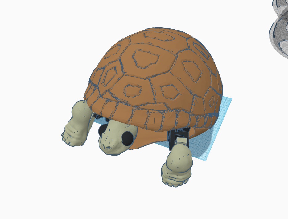
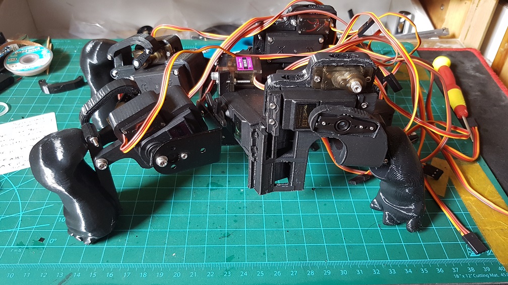
 This was what made into my final turtle with many component being edited into the next version.
With more time, I am sure that I could code the turtle be able to be scare back into the shell by another sudden loud noise – I tried to change the delay in my code to Millis multiple times and it do every action in the sequence twice so I sticked to using delay for now, which disabled me to write the activation code for using the sound as a trigger since it is in a delay loop. But, it looked really nice for now even if there is only one sequence of movement and I am glad that people were thinking that the turtle is cute when they saw it.


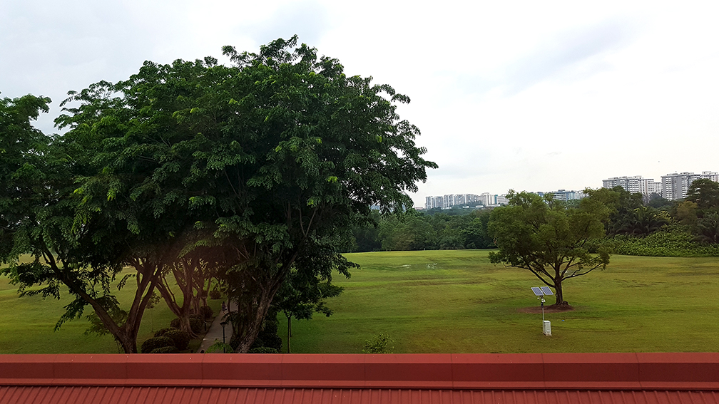
 I really like this random shot before the Stroll.
 After the stroll, when the sun finally rise.
 Luckily for me, right after we finished the broadcasting, it started to drizzle. And did I mentioned that we were supposed to do on Monday morning and we woke up at 5a.m. and it was raining so we postpone our stroll, it was really lucky for us that it wasn’t raining on Tuesday morning even when the weather forecast said would.
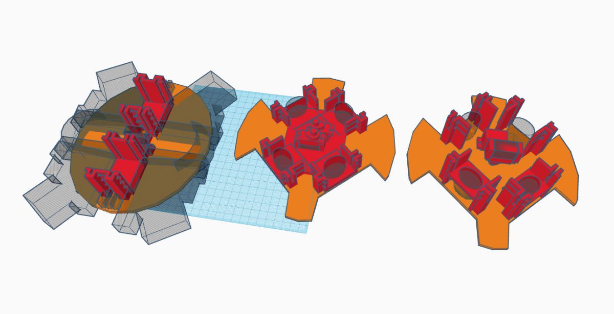
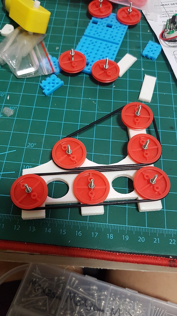
 This was originally the rough full size for the turtle base, Version1, Version 2 with 2 arm motor attached, and Version 3 with no Arm motor attached.

 And to check which layout should work.
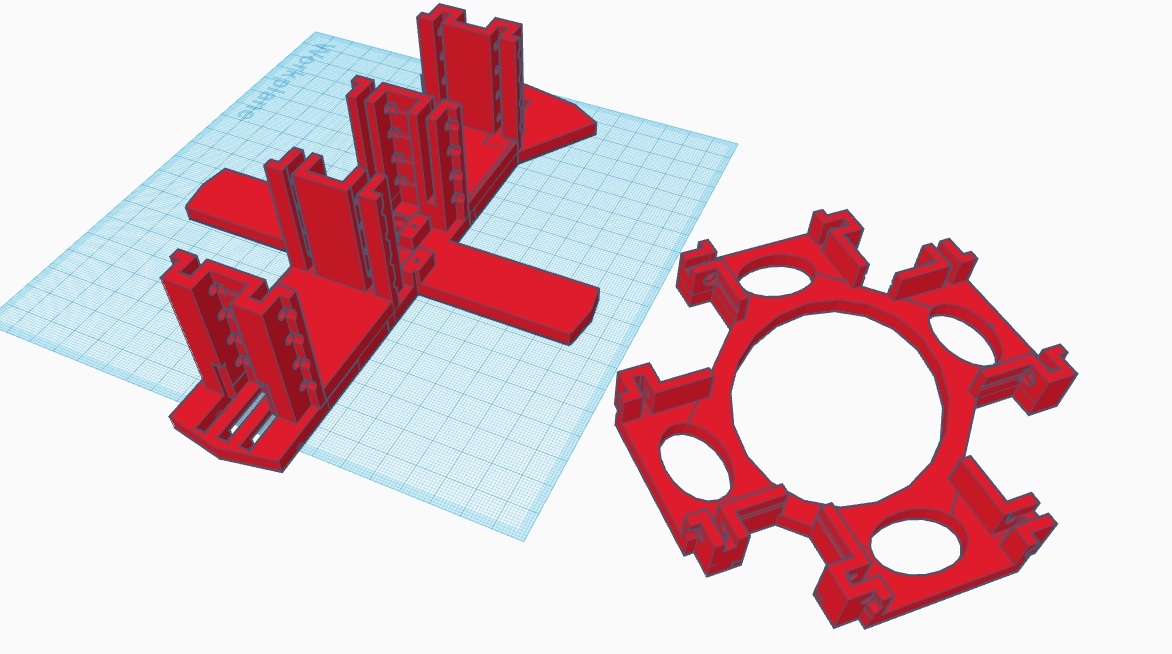 and since after I did more research on turtle, I realize that the bone structure of the turtle wasn’t straight and so I tilted the motors to give it an angular tilt for it to move more like a turtle.
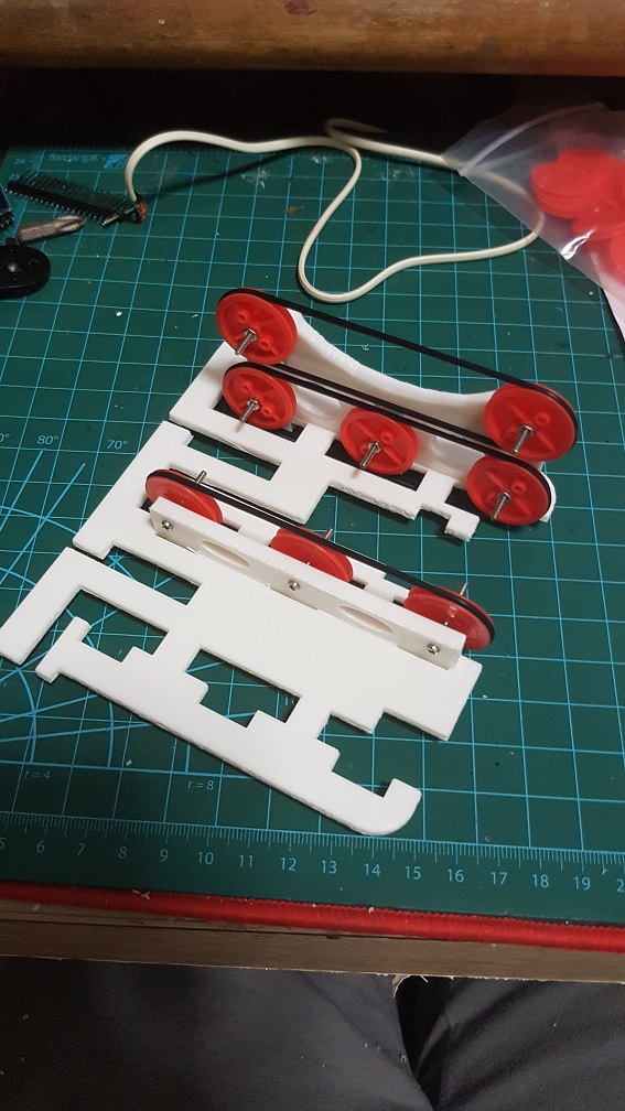
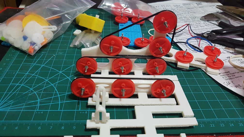
 I also modeled a arm motor connector and found out that this is WAAAYYY to long for it to work properly, and another problem is that there is still not enough tilt, so I changed from a 45 degree tilt to a 22.5 degree tilt.
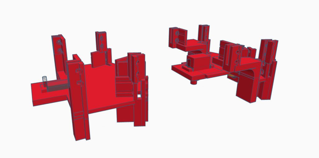
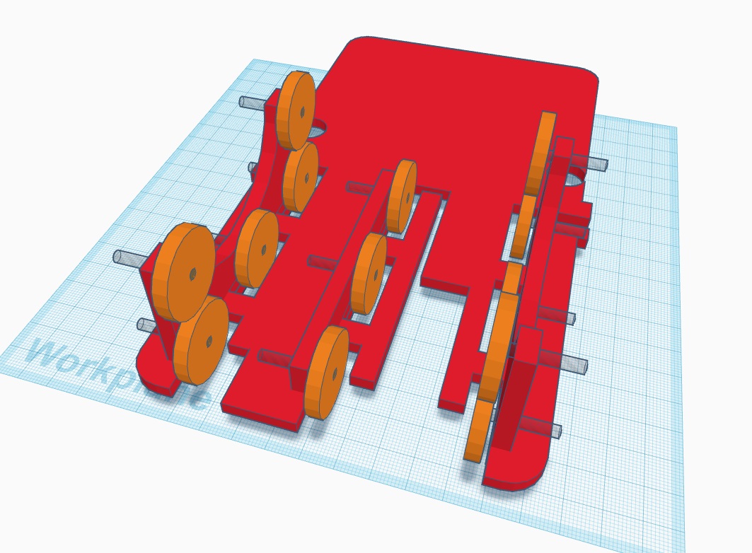
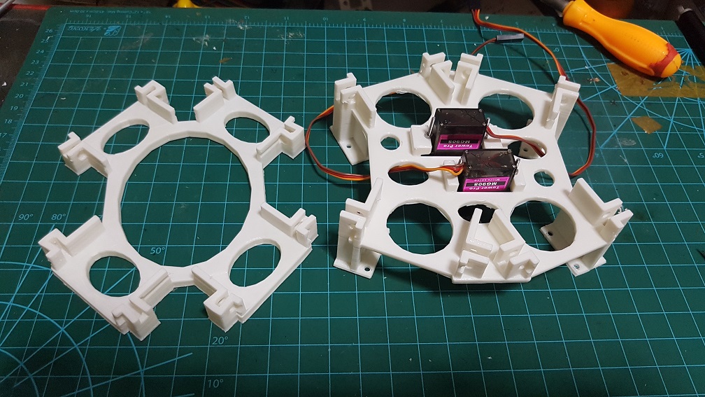 This is the Version 4 and Version 5 of the motor mount, I’ve decide to make it higher so to be able to turn the arm in the correct direction, I’ve also tried to add the middle servo which will control the turtle head retraction and head/tail turning.
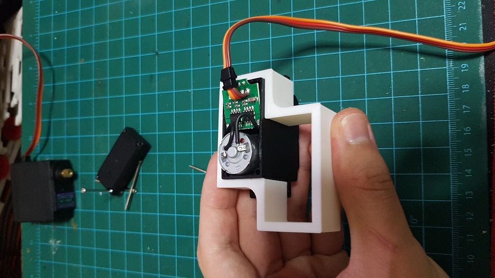
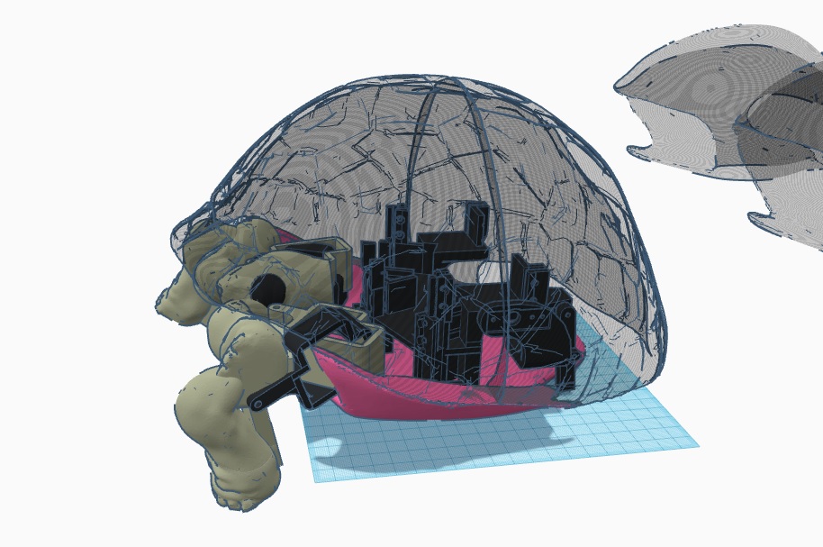
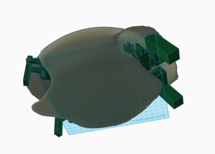
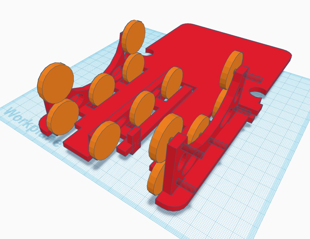
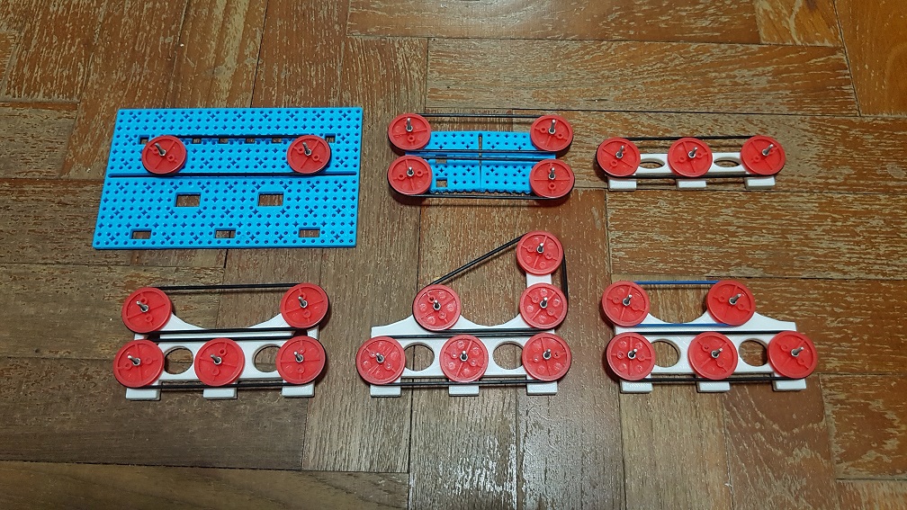
 This is with Version 5 base and version 2 Motor connector which are much shorter.
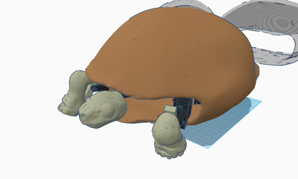
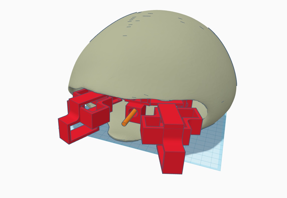 Next, I further edit the turtle shell and upscale it to see how it fits into my system, however i found many problems here like it doesnt fit well. Since I can make adjustments to the layout, I decided to use another method to do the leg mechanism.
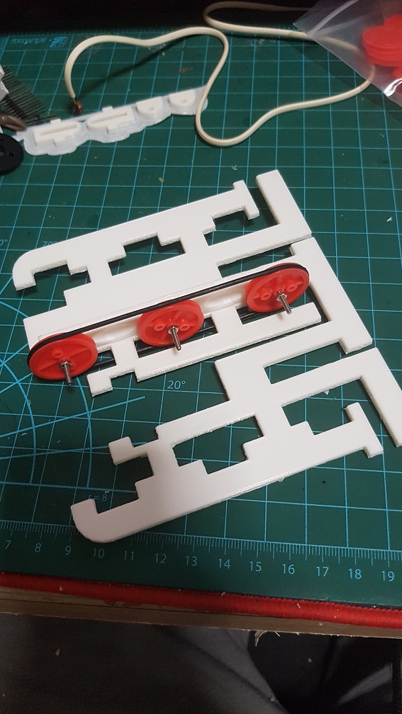
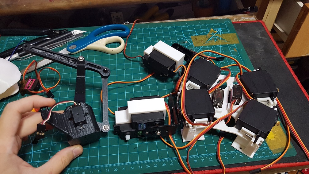 By combining this lever system straight into the leg.
 The 4 generation of motor connector.
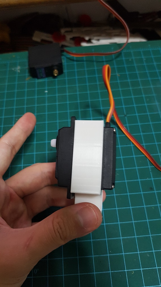
 This should be the mechanism I will use for the leg, I hope it works.
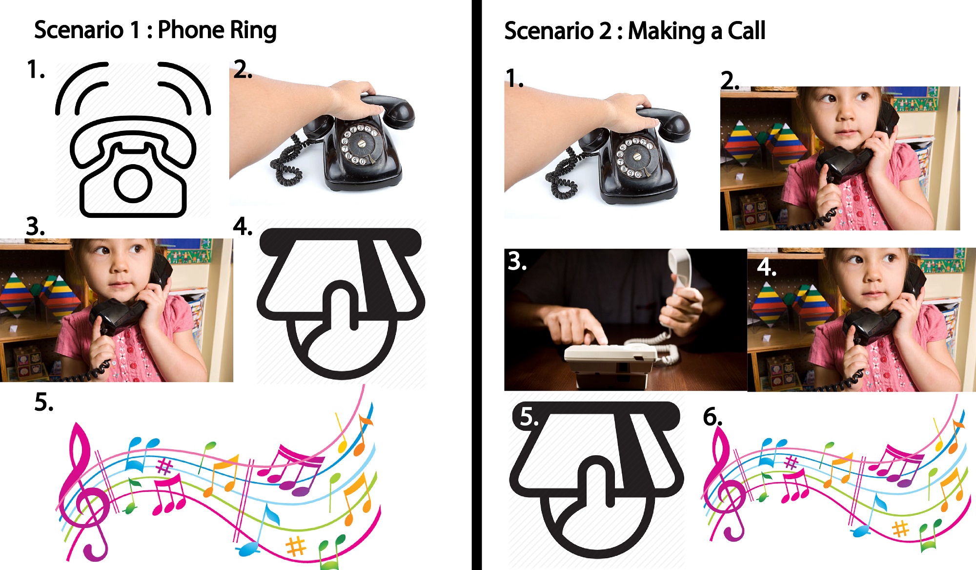
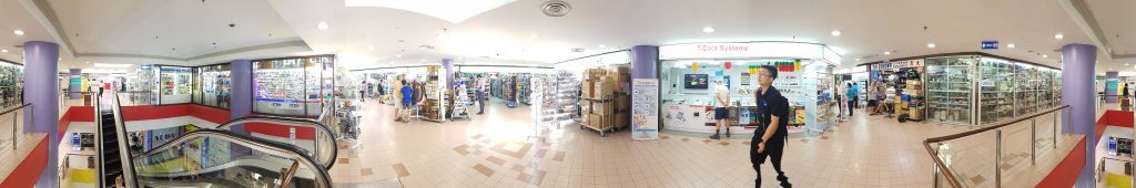
 This is the segment where we pass the phone to the next grid, we hope to achieve an effect that feels like we are moving in a straight line instead of passing in circle, we will only know the final effect when we view it from the grid.
 and this, just one video alone wont have any effect, but we hope to achieve a panorama spin effect through this when the grid is out.


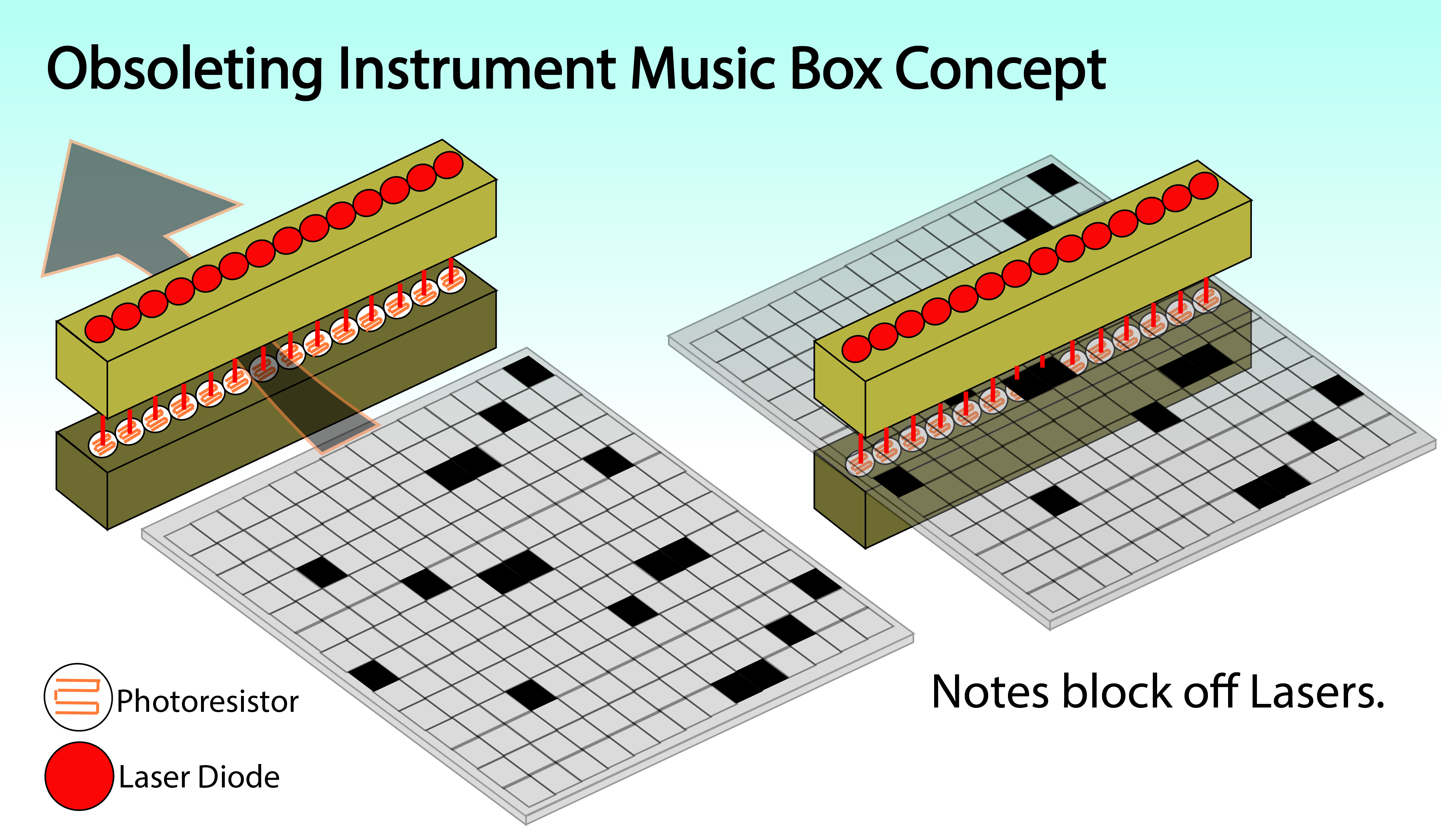
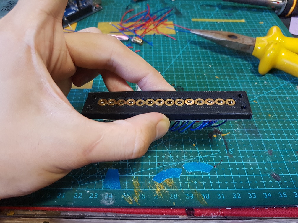
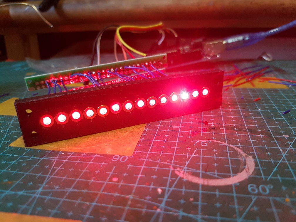
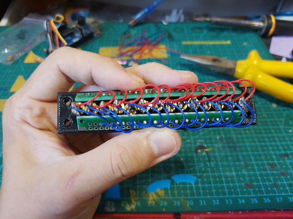
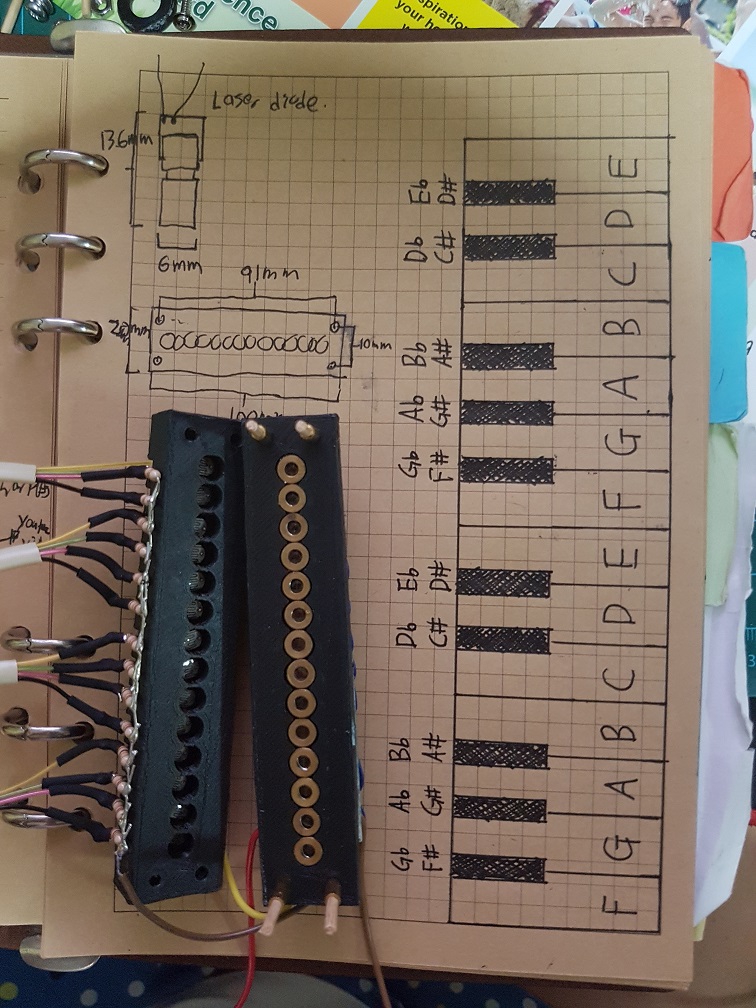
 Pew Pew PEW. look at dem laZEERRRRR
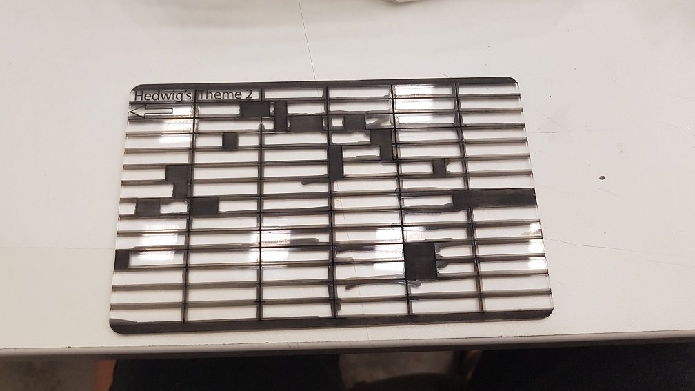
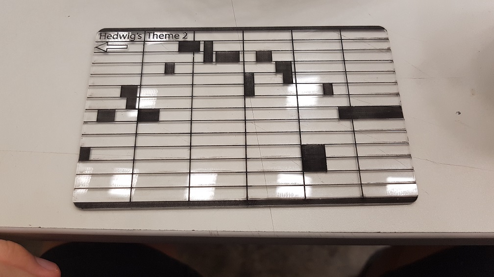

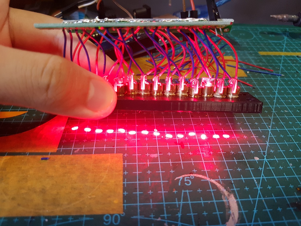
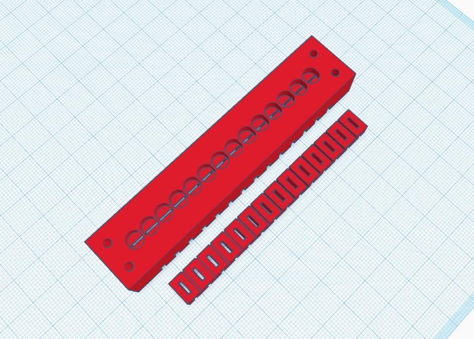
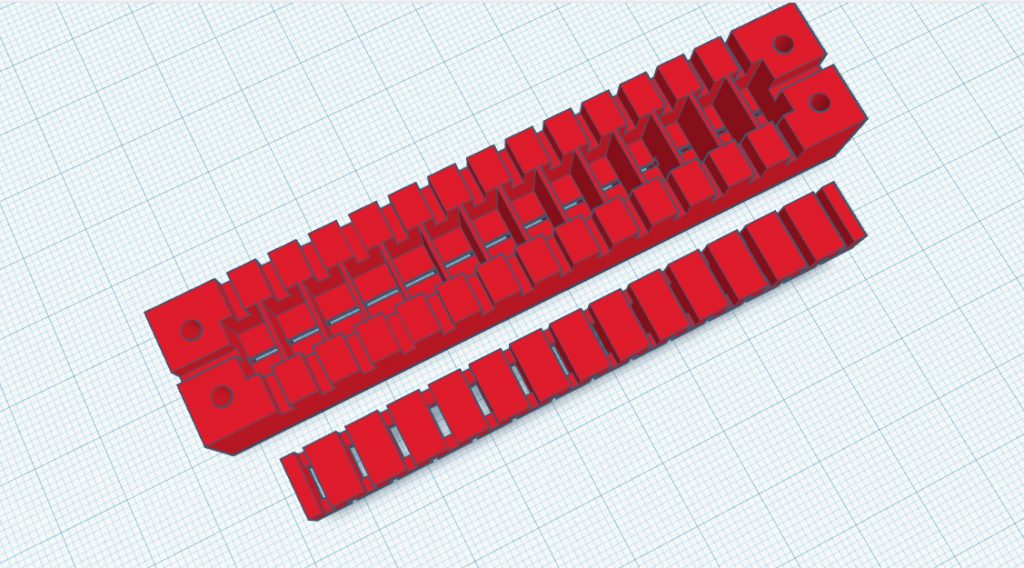
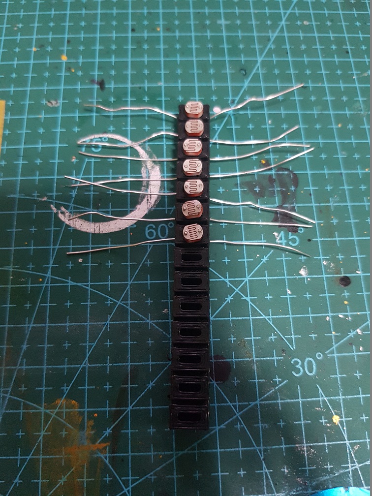
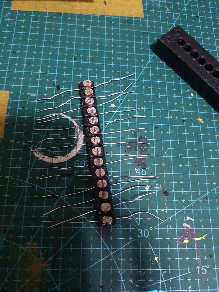
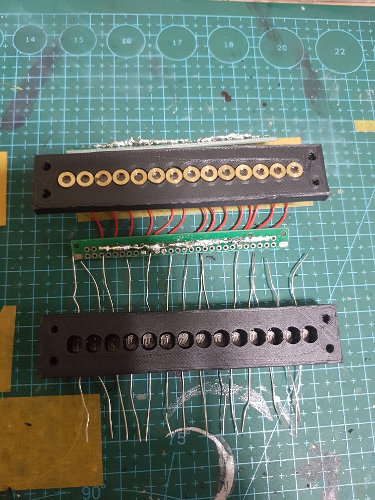
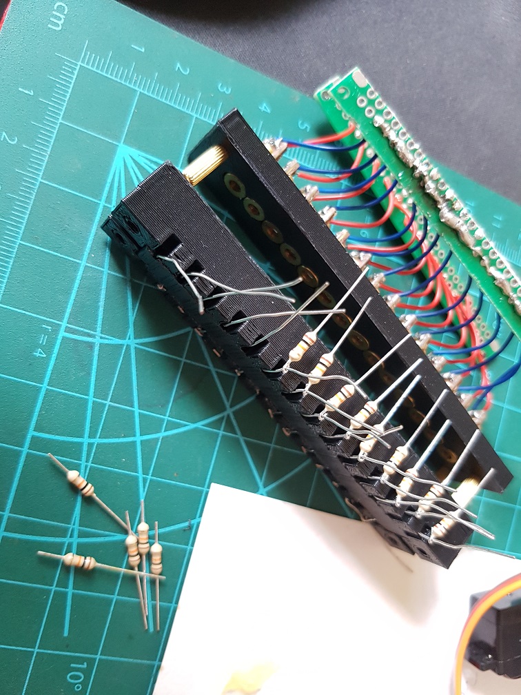
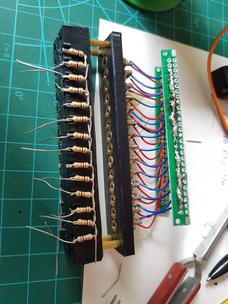
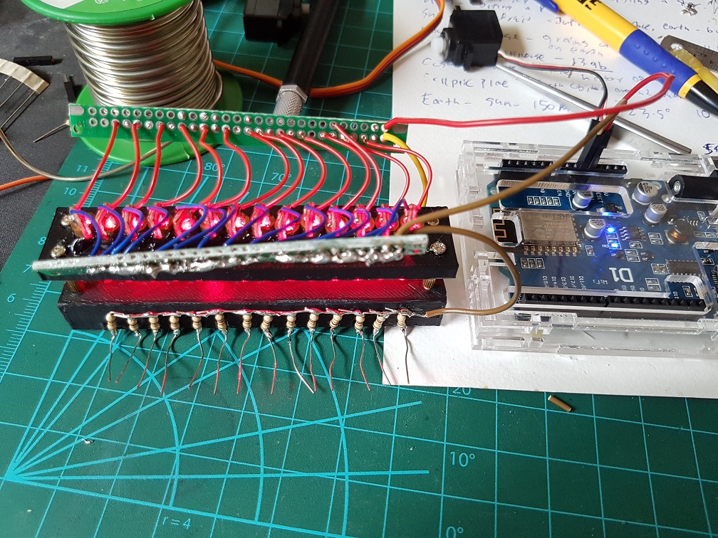
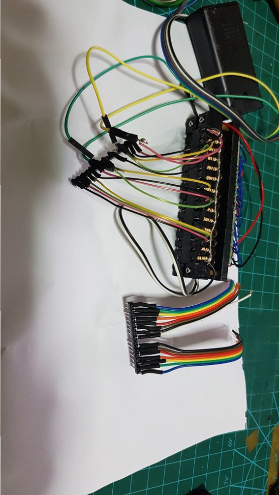
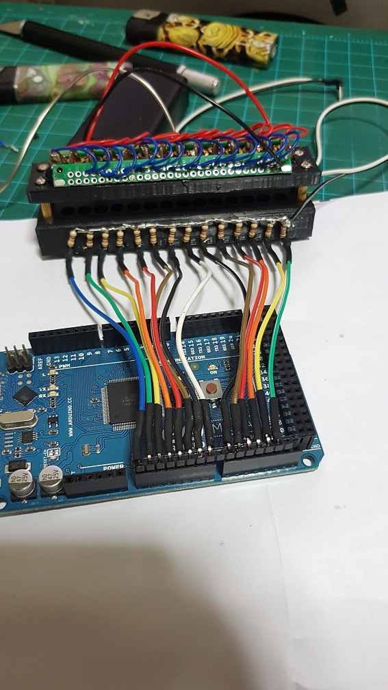

 The value will be higher than 800 when the laser shine directly on the Photoresistor and lesser than 100 when blocked, so I can simply write if( value <= 400), play tone 1.