The file size of this presentation was too large to be uploaded so I’ve screen recorded the presentation and uploaded it to youtube.
I’ve chose to narrow down my scope to just Unconventional Musical Instruments mainly because it will be more interesting and fits the time limit nicely.
The field of Bio Inspired robots is too wide and I think that we will benefit more by understand the different ways of how we could learn from the nature rather than narrowing the scope down and go deep into one of the sub division of bio-inspired robots.
The File size for the presentation is too large so I screen recorded the presentation in presenter’s view.
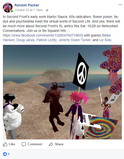
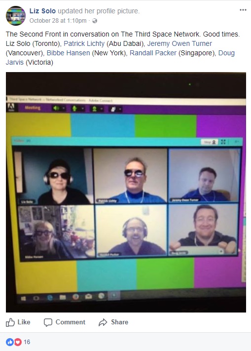
This was a eyeopening Network Conversation with five of Second Front’s member – Bibbe Hansen, Liz Solo,Doug Jarvis, Patrick Lichty and Jeremy Owen Turner This Conversation was HIGHLY advertised on Facebook by Prof Randall, and I found it really funny that the artists(Patrick Lichty) commented that they sensed danger in it and Liz Solo and Bibbe just found that comment funny and went along with it.
During the live stream, when there was a technical error when Prof Randall disconnected as a host and many disconnected together, I was lucky to remained in the chat room with a few of artists still streaming, they were really excited about the technical error, they Laughed Out Loud and being really thrilled about the fact that “Every where they go, they would crash the system.” JUST WHAT HAD THEY DONE IN THE PAST? I am also really amused with Bibbe with her animated personalities that she felt like a 8 years old kid in a 60 years old body where she gets excited fairly easily.
It is really interesting to see that the artists viewed their Second Life character (Avatar) sometime as themselves and sometime as a separate entity where they would mention what they did in their performance with “I” but also gave third person introduction to their Avatar during the introduction in the Network conversation. I guess they see the body of the Avatar as a separate being but shared the psychological, intellectual, emotions, conscious and all intangible aspect that made us human with the Avatar, this really seemed to be similar with the movie “Avatar”(2009 film) where the “Blue Avatar Thing” shared everything with the main character except for the physical body, and when Second Front logged out of the Second Life, the character will be inanimate and lose their “body” until they logged in.
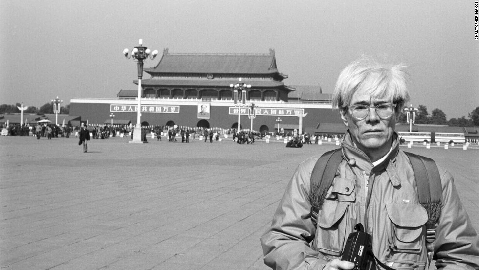
They also mention about the identity within Second Life where they did a work in the past by interviewing the people in real life and recreated the information they gained and place it directly into Second life, They would also change their Avatar appearance to replicate the other member’s Avatar and place a tag with the name of the character they copied and act as them for some time, also to add to this identity within Second Life, Second Front found it really interesting to place unsuspecting Real Life people like Andy Warhol into Second Front’s performance, as mentioned
“There was a Fluidity of Who was Where and Who Was What In Second Life”
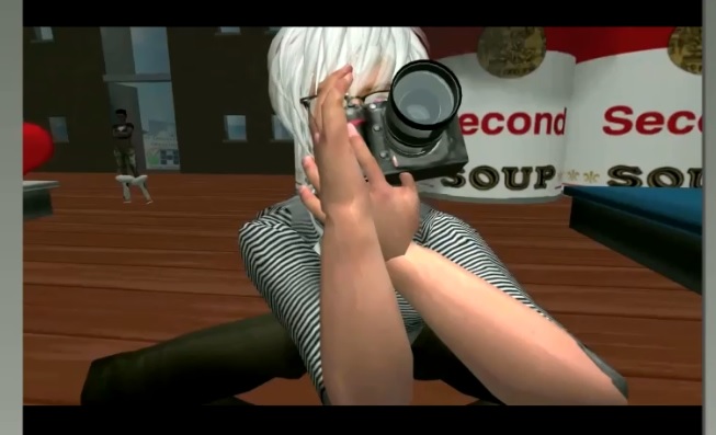
Andy Warhol
AndyWarhol in Second Front Performance, also notice the Campbell soup can in the background which is the reference to one of Andy Warhol’s famous work
Anyone could be anyone at any place, there was no clear boundary of what you can be in Second Life, this was what made Second Life so intriguing to a point that people lost themselves in the game.
Throughout the Network Conversation, Second Front talked about topics which were really got me thinking about the third space performance, as they are moving towards the VR, Patrick Lichty also mentioned the possibility that the neuro-plasticity might takes hold, if we gets too engrossed with the Virtual Reality, our brain may be rewired to evolve along with the technology and they briefly mentioned something about Neil Harbisson (I think, my ear-to-brain-to-hand function were not fast enough to write it down, but Patrick mentioned about some guy and I think its Neil Harbisson after I googled) where his brain was rewired because he uses sense that we would otherwise not use in that context, This is why the VR headset will someday affect our visual cortex, and by using VR, isn’t it just putting a screen to the third space right in front of our eyes and transport us directly into the third space? The future will be amazing for sure.
Lastly, I would like to agree the Network Conversation (I cant remember nor did I write down who said it again, and this is not the exact words but what I interpreted and summarized) that
“Performance is all about the body, what if we take the body out, we have emotions, we have feeling.”
When we are in the Third Space, it is real as there are all of what made us human, except the physical body. These panels(the Adobe Connect grids) is a great example of bringing people together through Third Space.”
If there are anything that I learnt from the Network Conversation, It further emphasis that the third space is a very new platform for human to be in and we are still in the process of integrating into it. It may take some time before our brain complete the rewiring so that we can have the thirdspace as a new human sense through the “Evolved neuro-plasticity” which might not even happen, but while the possibility are endless, so why not just learn from the Second Front and to have fun in doing things we all like while enjoying the process of creating something regardless of the end result but only focus on the enjoyment of process.
Nonetheless, the Second Front enjoyed and had fun in the Network Conversation!
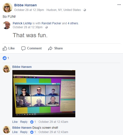
Bibbe Hansen thought the network conversation was fun.
Liz Solo thought the network conversation was fun., even though she was lagging. LOL
Patrick Lichty thought the network conversation was fun.
This Co-Broadcasting thing is definitely new to all of us!
the best part of the co-stream is that we can communicate to each other with very little lag between in comparison to the usual broadcast where there will be atleast 7 seconds with optimal connections. Co-Broadcasting could possibly be used in our final project as our idea for the final project is to go through the barrier of the broadcase and “appear” on the other side of the stream. When doing our two occasion in the Co-Broadcasting, we’ve got some interesting shots and we tried to build towards our final project.
Co-Broadcasting 1:
Posted by Su Hwee Lim on Thursday, 12 October 2017
Co-Broadcasting 2:
Costream test 2 Su Hwee Lim
Posted by ZiFeng Ong on Wednesday, 18 October 2017
1 – The lighting is really important, in our first stream, the both video seemed really nice next to each other, but in our second stream, as the lighting is different, it is very difficult for the viewer to believe that we passed the item over since the lighting is way off even when it is the same thing. Like Bao and Makoto’s co-broadcasting, since it was taken in the afternoon, it look really nice because they have similar lighting.
2 – There needs to be communication between both of the broadcasters so that we can coordinate our actions better be simple thing like a count down but we need to think of a way to remove the countdown.
3 – if we want to pass thing over or anything that require the use of the split, we must do it so so both of the broadcaster can slowly merge the object on the split.
Overall, there must be more testing for us to fine tune our actions and the difficulty level will be much higher if there are 4 broadcaster at the same time. Maybe one way is that we can use the co-broadcast as a communication tool instead of the final piece so we will have two phone each, both phone broadcasting at the same time while one is in the co-broadcasting mode and another is on the normal broadcasting mode so that we could communicate through the co-broadcast live.
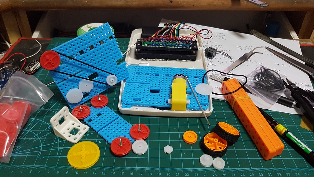
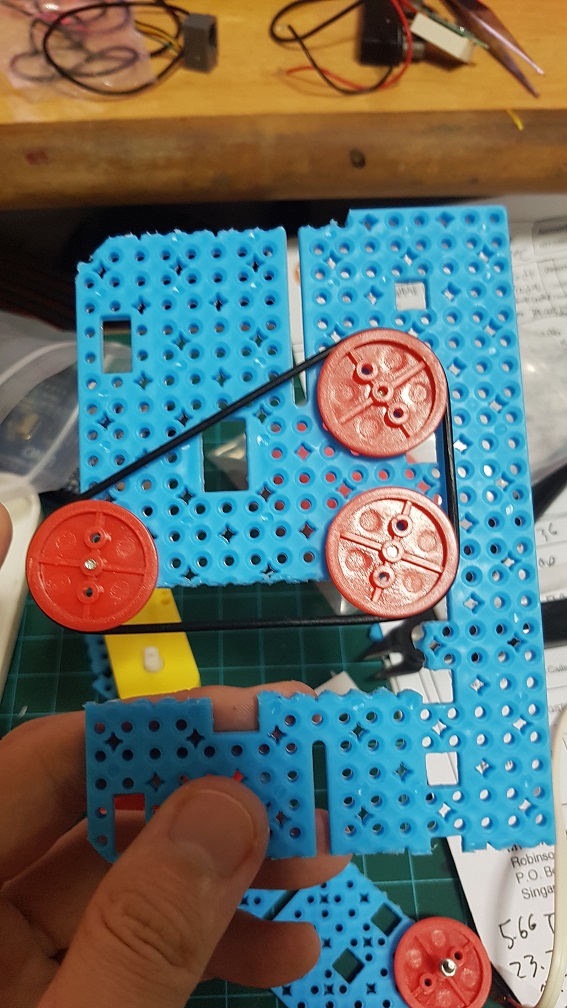
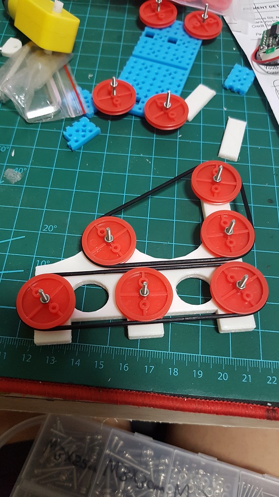
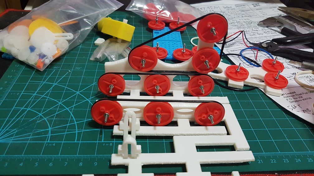
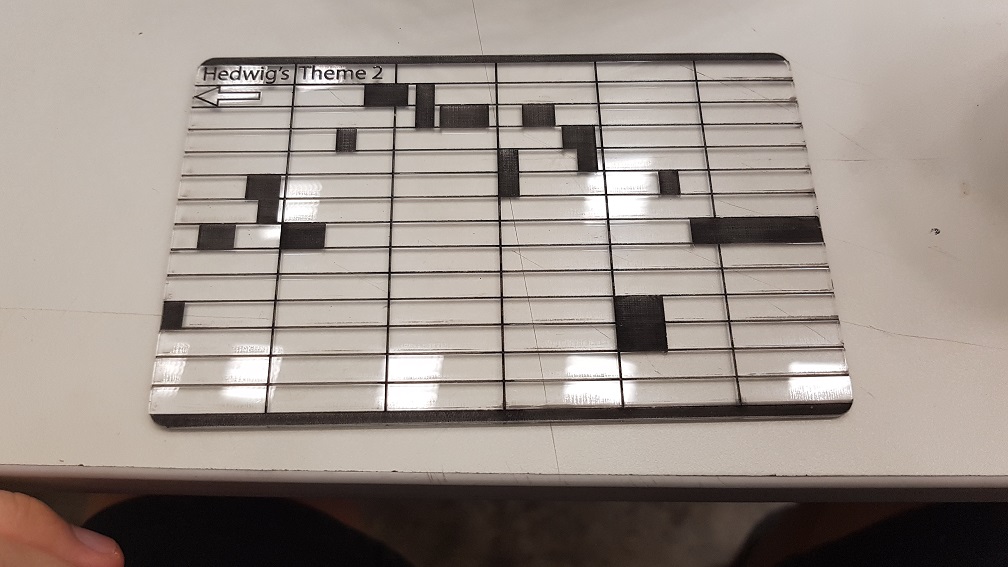
After the last post where I’m almost done with the laser reader and there are still improvements to be made to it, but I will focus on other component and will come back to make it sound nicer if I still have time, for now, I need to slowly build towards the completion of Obsoleting Instruments first… I will need to a way to feed the music sheet into the laser at a constant speed, so after some research and thinking, I could use DC motors with gear box that drives the music sheet through a belt
system, so, with that in mind, I purchased some special rubberbands and the belt driver thing, as well as some gears and shafts and the plastic DIY construction pieces to test it out.
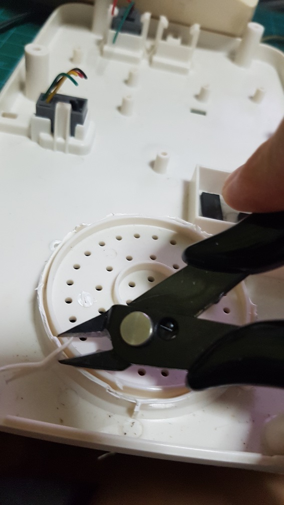
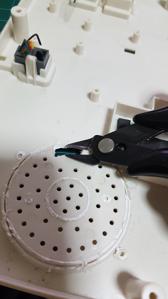
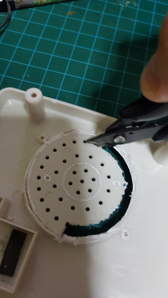
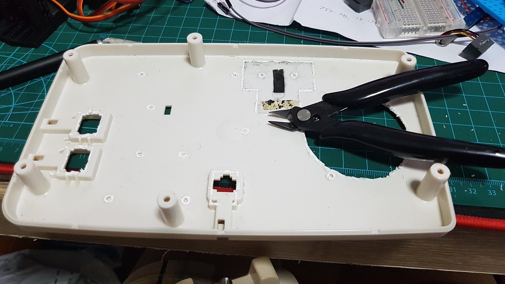
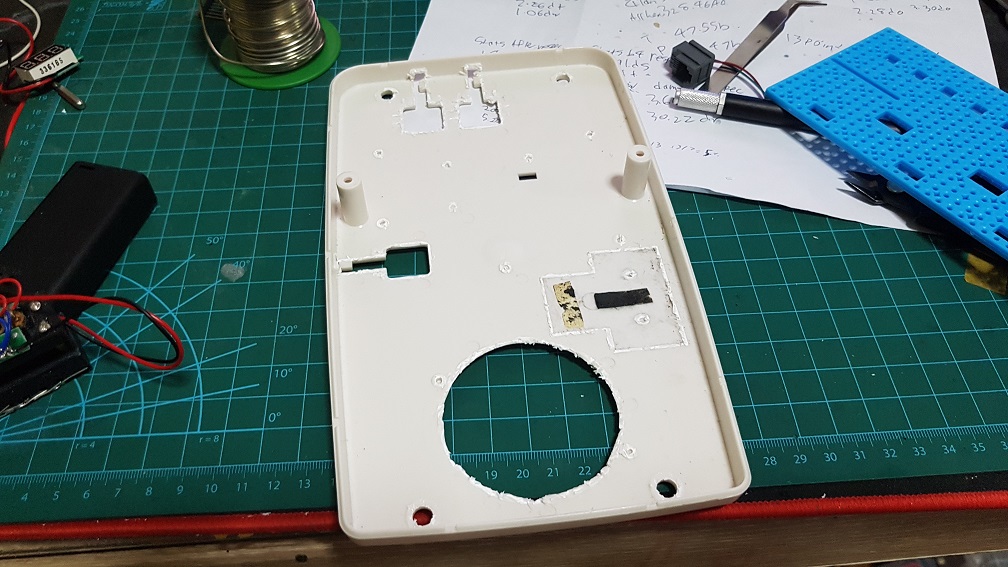
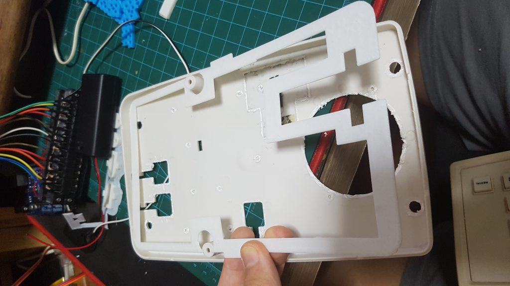
First, Since I’ve got the Landline Telephone, i need to clear the little plastic pieces inside to make room for all my components, and I thought it would be a simple task, but MANNNNNN ITS SOOOO INTENSIVE(because i dont have a proper tool to do it)
Theres a Chinese saying “Small knife cuts huge tree” its a torture and yet quite satisfying for me.
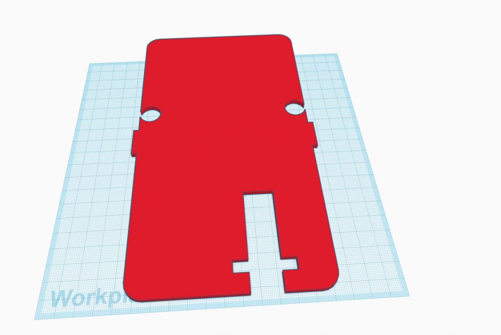
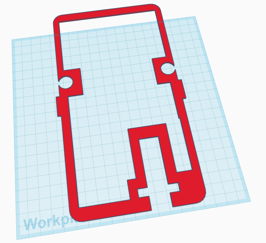
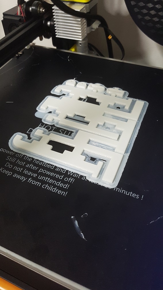
After I got the usable distance, I proceed to 3D modeling the parts that is required.
my general sizing to be used in the Telephone
a test version to test if the size are correct
apparently, the 2 holes are too far from the back and the overall length is 2mm longer, so I need to shorten it for it to sit nicely in the casing.. Luckily I test printed
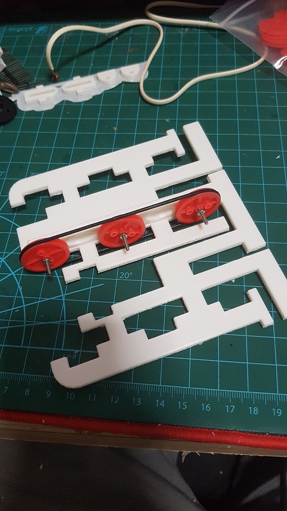
It worked really well, but there is only one problem, my top cover of the phone could not close as it is slanted, so I have to shift the whole plate to the back, or place the top belt about 40% inwards but I cant just shift both belt wheel as there will be the laser reader there. so…
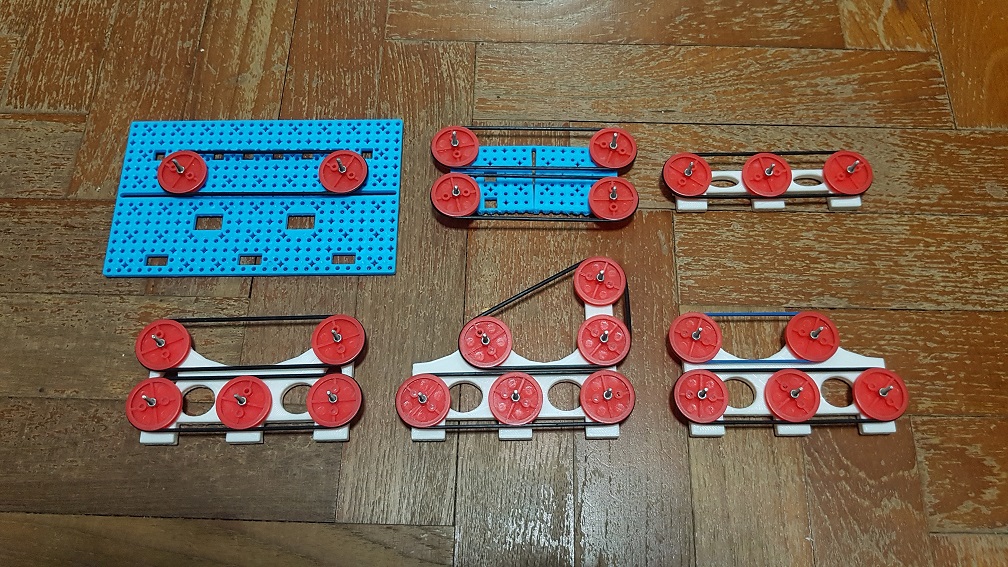
Back to the test of belt wheel distances
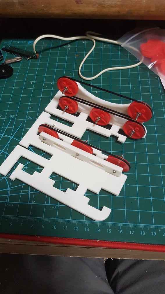
printed version, then this thing is too tall so i have to reduce again.
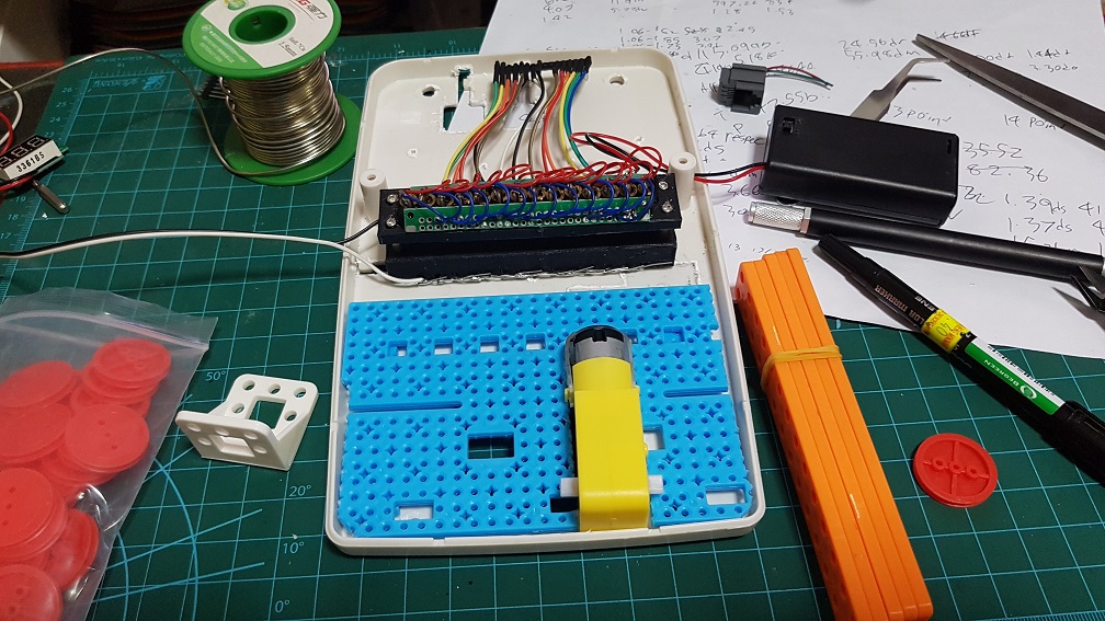
placing it in and into the phone to test.
in the end, I tried 6 version and ended up using a shorter rubber band for the top belt. WHY DIDEN’T I THINK OF THAT BEFORE!!!
I will settle on my 6th one for now, since this is only half of the system, I need to get my music sheet up first for me to test the speed of the motor with this system since if half doesn’t work, nothing can work.
First, you will need an EZbuy account, it will be really worth it. Best part, they have collection point from Canteen 2 in NTU!!
Buying from Taobao /EZbuy won’t guarantee the quality, occasionally will you receive item that doesn’t work but they are CONFIRM 3X to 10X cheaper than Simlim Tower.
Waiting time is anywhere from 5days to 3 week (5 days only if you are really lucky that the seller send your order out the same day and it finished inspection the next day in EZbuy warehouse PLUS you used Express shipping which is $2.99 per 500 gram) if you are REALLY UNLUCKY that the seller gone MIA after you purchase, good luck, but that shouldn’t happen with the link I gave as I bought from them and all is good.
Tutorial here for those who don’t know how EZ buy works,
For weeks, I’d been thinking that my code was wrong hence I cant move more than 2 motor at the same time or it will corrupt the system….
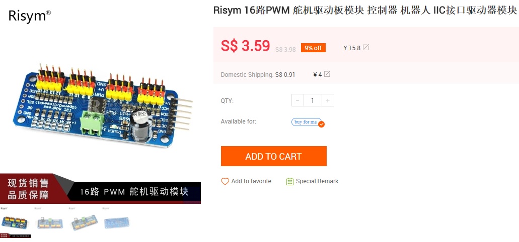
And in the end, it wasnt my code, as I was using PCA9685 which is a servo driver which I bought online and thought that I could control 16 motors at the same time, Yes, it could and the code can work.. the problem is the power supply. NEVER HAVE A SERVO DRIVER’S MOTOR POWER SUPPLY POWERED STRAIGHT FROM THE ARDUINO!
I finally found out today that was the main reason, when the motor drains too much of the Arduino’s power, it will brownout, causing erratic behaviors in the motors which was my main problem up till now, so instead of limiting myself to code up to two motors to move at the same time, I could potentially move all 16 motors just by finding another power supply.
15:15- 16:10
My Brownout will occur when I run 4 servo at the same time, so 3 servo running simultaneously is the maximum for my current power supply, There are ways which I could solve this problem.
Using a battery which could supply 6V power at 10A or more, after my research, battery are rarely rated at 6V and 10A is just too much for a battery, even if they do, it will drain the battery out really fast unless I am using a HUGE car battery on 12V and step down the supply using a Voltage Regulator.
Using Multiple battery at 5 V or 6V and parallel them to increase their current, since this will be the most expensive out of all option, the only way possible to get this done is to series 4xAA battery and parallel multiple group of 4xAA to create a powerbank, the downside of this will be the voltage drop overtime due to lesser power in the battery.
Using a power adapter with the 5V or 6V at 10A, and this will probably be more feasible due to the availability of 10A power adapter in the market, or I could use a 12V 10A power adapter along with a Voltage Regulator and step down it to 6V. I think this will be relatively doable because it will have a stable supply and I do not have to worry about recharging my battery, moreover, I might be able to supply power to my Arduino at the same time too.
In conclusion
I will try to find suitable power adapter along with voltage regulator, if this still don’t work as well as i thought it would work, I probably can use a capacitor to increase the current rating(I am still not sure how does this work, but I’ll figure out)
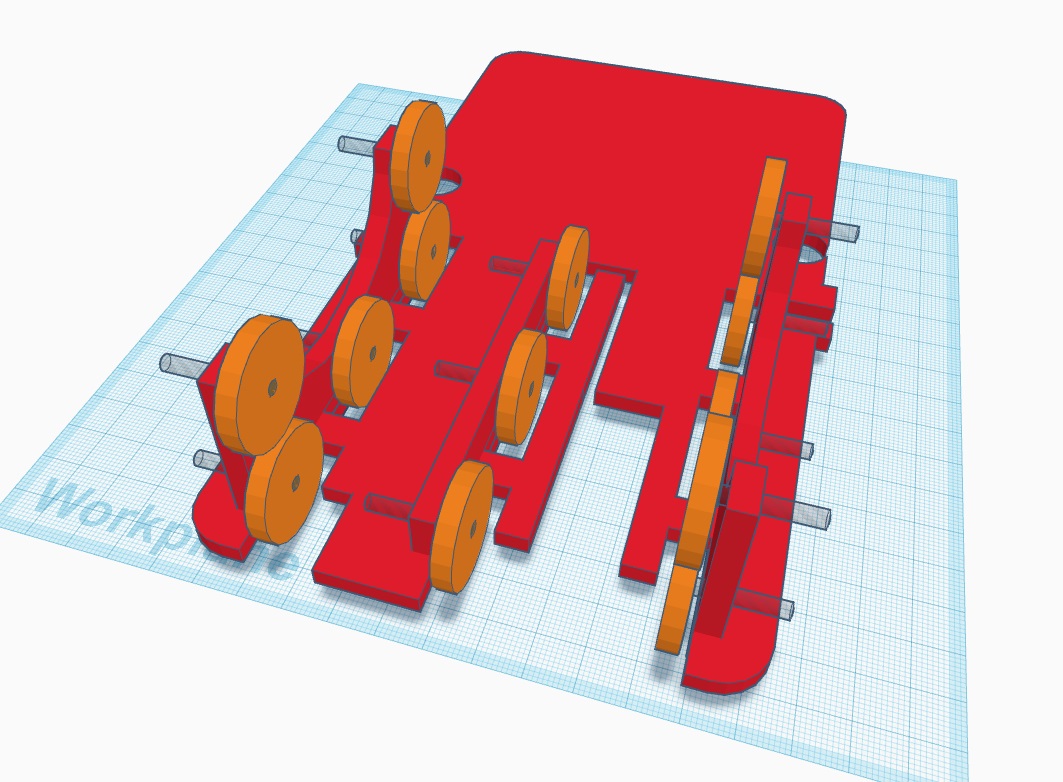
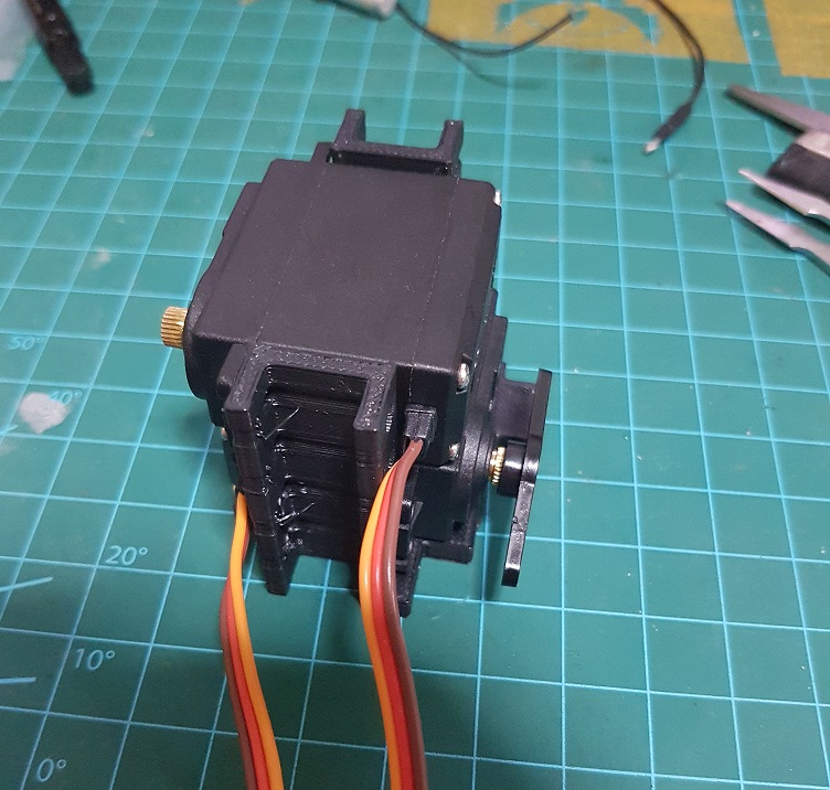
After the Study model of the last part, where I stopped at the lever system and realize that it is not as strong as it should be, my improved method is to use 2 servo to do the same action, After a long time trying, I found out that the overall height of the servo will still be as high and as big as a standard MG 966R servo motor, and the MG966R will provide significantly higher torque than 2x SG90 at roughly the same height.
So my new solution to this is to use the heavier and stronger MG966R as the feet motor. Since they are relative big, I need a system to fully utilize the height and the movement of motors to make it as compact as possible. Since the center of the turtle shell is usually the tallest part, it make sense to stack the first rotating joint (the shoulder) above each other to greatly reduce the total size of the turtle by making it slightly taller.
Improved prototype of the system which reduces the shakiness of the Shoulder Motor(which is important as Shoulder is the first joint, if this vibrates, it will be amplified become very obvious in the feet.)
after countless of testing to get the perfect balance of height in horizontal and vertical, this system should be able to progress into what I will use in the final, there are still improvements to be made in the base height of the Shoulder Motor as when the Arm spins, it will still touch the ground.
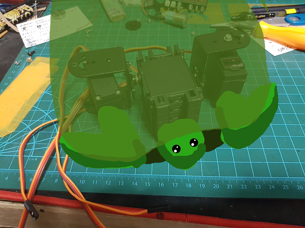
for now, it probably can walk and hide like this..
Next up is to further refine this system and find the suitable system for the Elbow joint.
Conductive paint had been here for some time and the application for seemed to be really a next level to interactive devices. This is an example of the usage of a conductive paint, Electric Paint Lamp Kit.
The Conductive Paint Lamp Kit is a simple product which springs from the novelty of Conductive Paint and what made it so special is that it is the most basic element of any circuits- forming connections between parts. With conductive paint, we could form electric circuits on any paintable surface which means the possibilities are only restricted by the surface and our imagination, In the Lamp Kit, it uses only simple Light up board, some printed paper and Conductive Paint in different combination to form 3 different variation of lamp, if we were to use other modules of sensors or output, I am sure that it would be really fun to play with these.
Like for example, if we were to use projections on top of the conductive paint on a wall, it would be like so.
This is definitely an interesting project to be done and would be possible for us to complete with our current knowledge after some explorations.
Another project which latches on the idea on a set of more advanced conductive paint is this, the Electroluminescent (EL) Device.
The Electroluminescent Strips could be created by using a few layers of different paints.
and how to create that exactly could be found here:
In Conclusion
The element of interaction within the Lamp kit not only acts like a Lamp, it is also a DIY kit which the user would participate in making it into a final product which gives the user a sense of involvement and increase their liking on the product as it was made by them. Maybe I could incorporate this idea of involvement into my final project where the users could create something that runs in the system which I created.
Also, Conductive Paint seemed really interesting to play with it and the potential of it is endless, we should be able to see better Conductive Paint and Conductive Paint Projects in the market really soon and I probably will purchase one to play with and maybe make it into a project or something.
A Continuation from the previous Idea and Research, Part 1 where I wanted to do an Animatronic Turtle.
The Difference between a Turtle and a Tortoise is that all Tortoises are turtle and not all turtles are tortoise. Generally, Tortoise live on land and turtle lives in water most of the time, with exceptions which I’ll not go into. However in my Project, I’ve decided to use “Turtle” as I simply prefer the sound of Turtle more than Tortoise.
First thing.
How do Turtle/Tortoise walk?
Tortoise are cute! and the way they walk naturally are quite robotic =D
29:43 – 30:20 where they talk about the locomotion of the tortoises
I could use a lever system to move the front and back legs so that I could use smaller motor and all 3 motor placed in the shell so the overall weight of the feet will be greatly reduced to allow me to use smaller/weaker motors.
From my research I’ve done and found this EEZYbotARM on Thingiverse which I could use it to study the mechanics I could potentially use in the feet of the Turtle.
So to understand how fully it works and if there are any restrictions to this lever system, the best way is to having a study model to study how I could incorporate it into my Turtle. I also purchased a few servo few weeks ago and they also arrived so I used them in the study model.
The movement is really smooth and the movement coverage is definitely good enough for my turtle,However this system could barely carry its own weight as the base is relatively heavy, this Lever system could work great as a Type bot kind of project because doesn’t need to carry the base of the robotic arm, in my opinion, this probably wont work in my Turtle since each leg will still carry its motor weight because they are all in the shell, so having Motor(A) not carrying Motor(B) is of less importance since Motor(A) and Motor(B) will ultimately carry the weight of (A)+(B)+the mount+components+the shell in the end.
In Conclusion
I’ll need to find a more efficient system or use a bigger motor to do the work of lifting everything in the shell along with the motors and still able to cover the movements. Now my main concern will be
Weight of motor VS its Torque
Size of Motor (slightly bigger motor will result in MUCH BIGGER TURTLE which I’ll try to avoid as I wanted a COMPACT turtle, not a monster.)
Movements of motor especially within the shell.


 This is a take from our second co-Broadcasting which we focused on testing for Final project. we did the face merge thing like in the adobe connect.
 Since we have the same object, we decided to use it as our advantage and “pass” to the other person and merge it on screen so it appeared to connect in the split of the screen.
 Another Adobe Connect trick, so now our body parts are not limited to spatial restriction and can travel through the third space. (somewhat)
 and we tried to synchronize our movement which is REALLLYYY difficult.
 Lastly, as Makoto suggested, the side profile it kind of difficult but it is really interesting if we can get it to synchronize and turn our face. Which we did and had a relative success


 Pew Pew PEW. look at dem laZEERRRRR
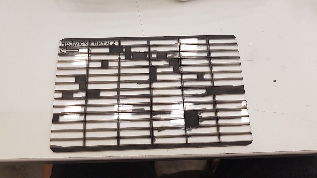


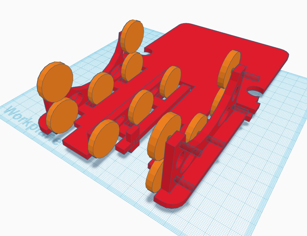
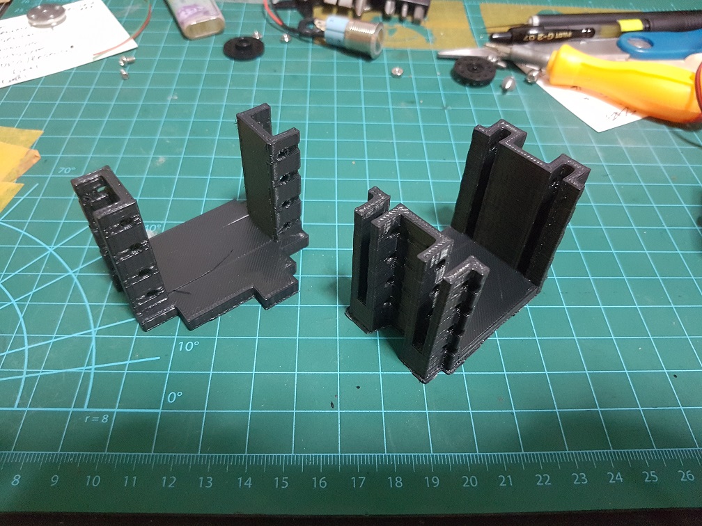
 Prototype of stacking the Shoulder motors, I’ve realized that the left motor should be at the bottom and right motor should be at the top as one will spin clock wise and other will spin counter clockwise to make it the same height when their pivot are not centralized.
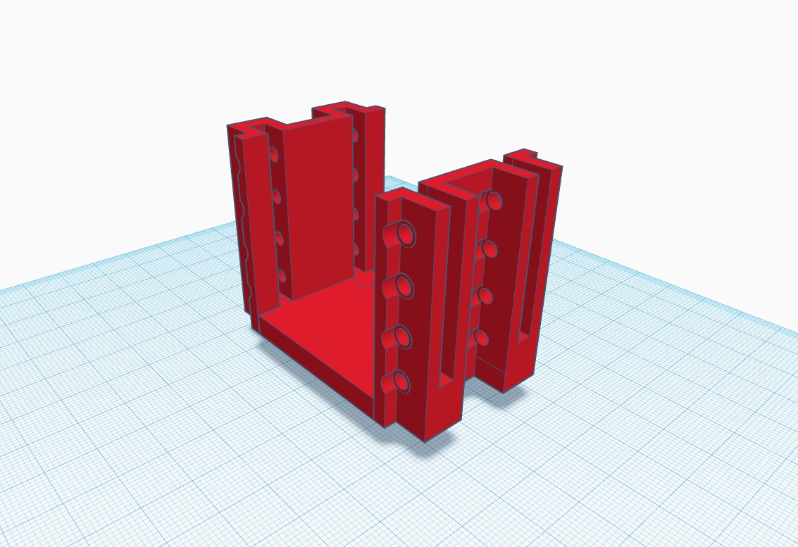


 This is how a Tortoise retract its head, by bending its “neck” inwards. maybe I could emulate this.
 The two motor is at the base of the mechanical arm(Typebot), in comparison to our typebot,
 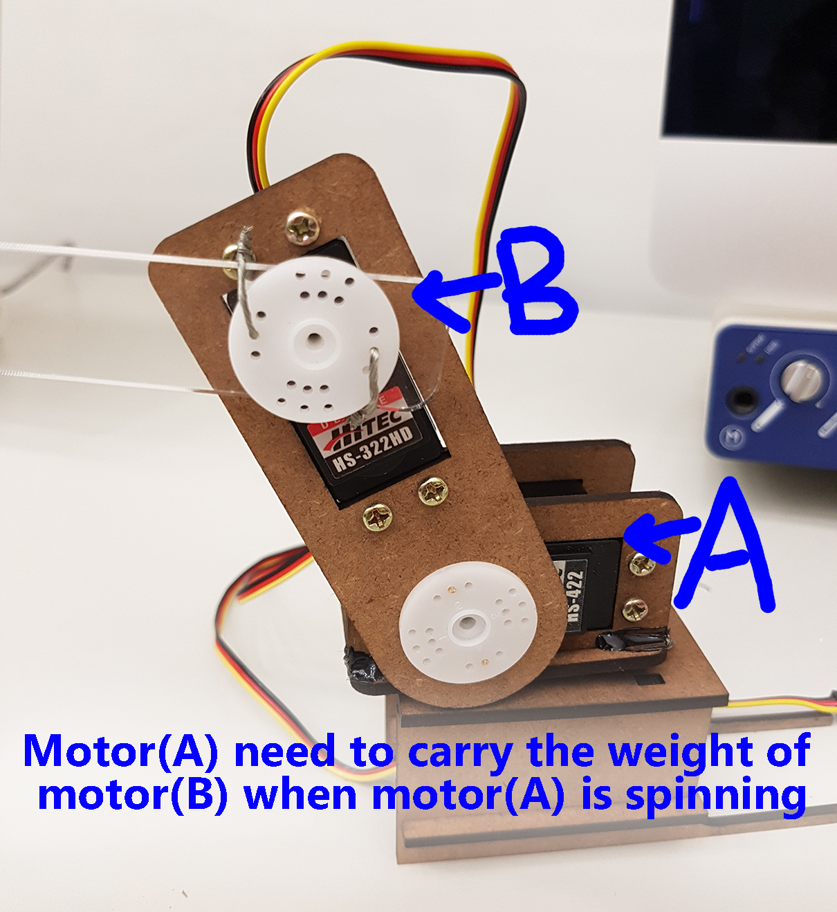 This Typebot system is less efficient unless the torque of the motor far exceed the weight of the system and only a when there is a short (A) to (B) distance(longer fulcrum, more torque needed to turn it)