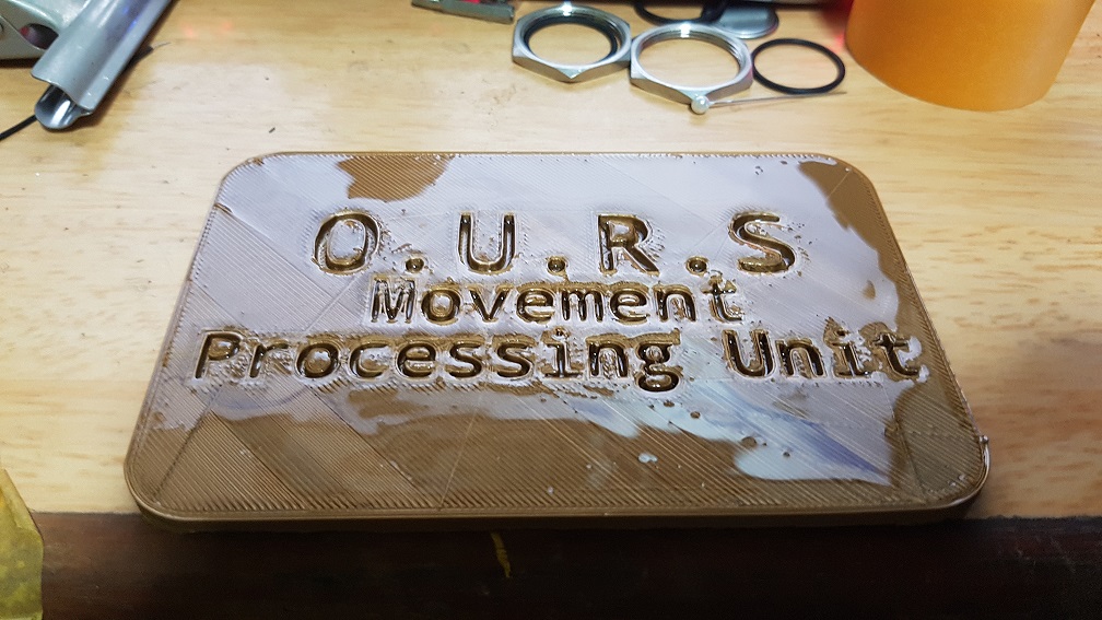
3D Print + Resin treatment as I want to see the effect of applying Resin to 3D printed parts, It was airbrushed with gold paint afterwards to test the paint holding properties of resin, which to my surprise, is good!
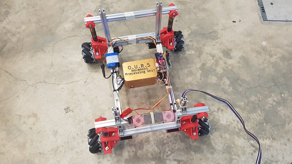
after attaching it onto the base of the Robot, this case serve as a protection of accidental dislodge of the pins (while still maintaining the function to switch out the board) from the arduino as well as adding a slight water resistance to it,(you never know if the visitor will drop a cup of water onto my robot during the show)
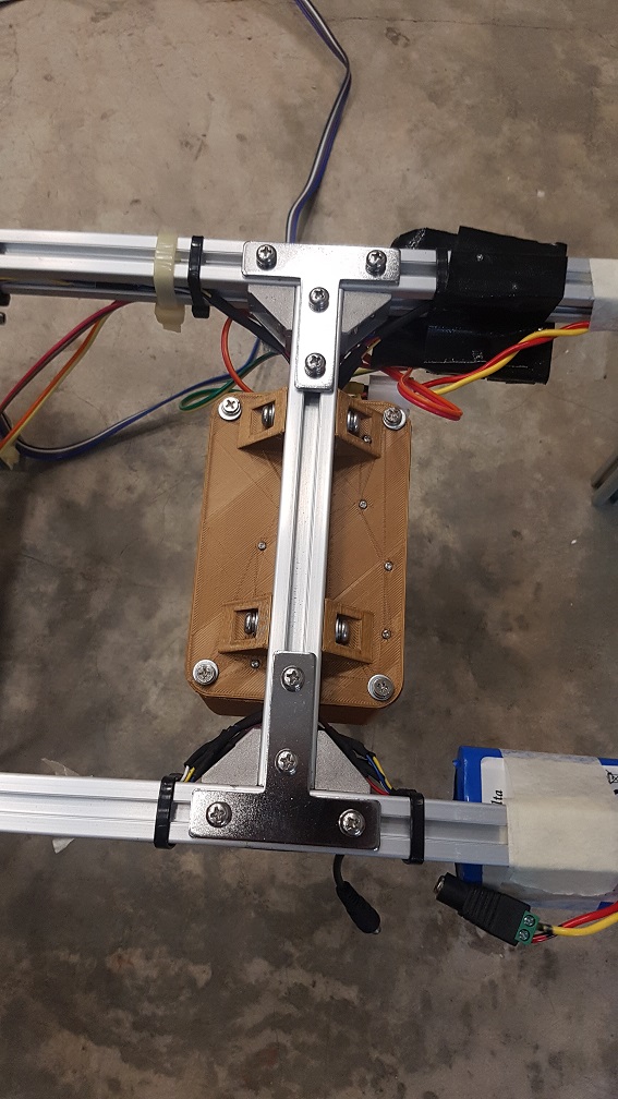
Parts Strengthening to make sure nothing come loose:
original connection of the aluminium profile. 4 screws with spring washer at each connections on the 90 degree joint.
added a T plate to secure the joint, total screws with spring washer = 8, and it is structurally stable (the screws hold all axis of vibrations.)
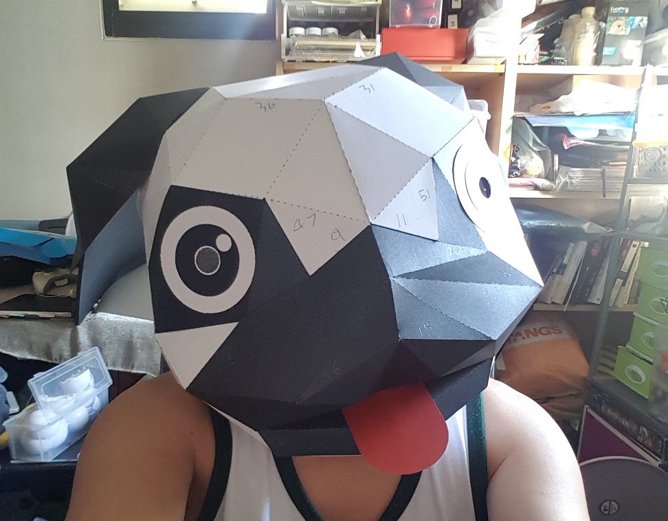
Experimental Head for the robot:
3D Paper Model, cut them and stick it together
Dog head. Why a dog? because dog is human’s best friend and you’ve heard of search dog, guide dog, which is exactly what my robot is about, and it is cute.
after cutting the eye out and replace with the LED matrix with arduino nano. i would say it made it really interesting to look at just with the eye that moves.
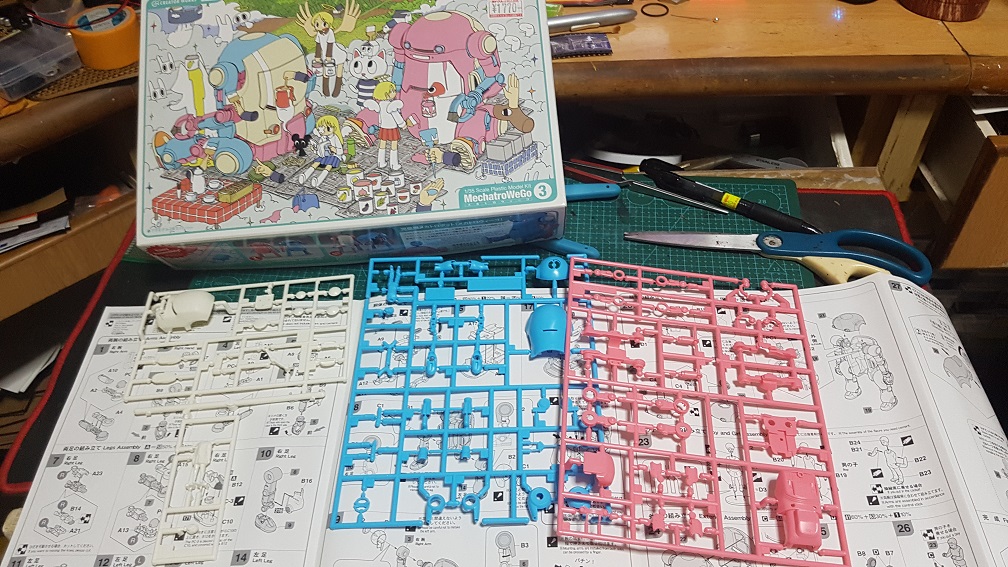
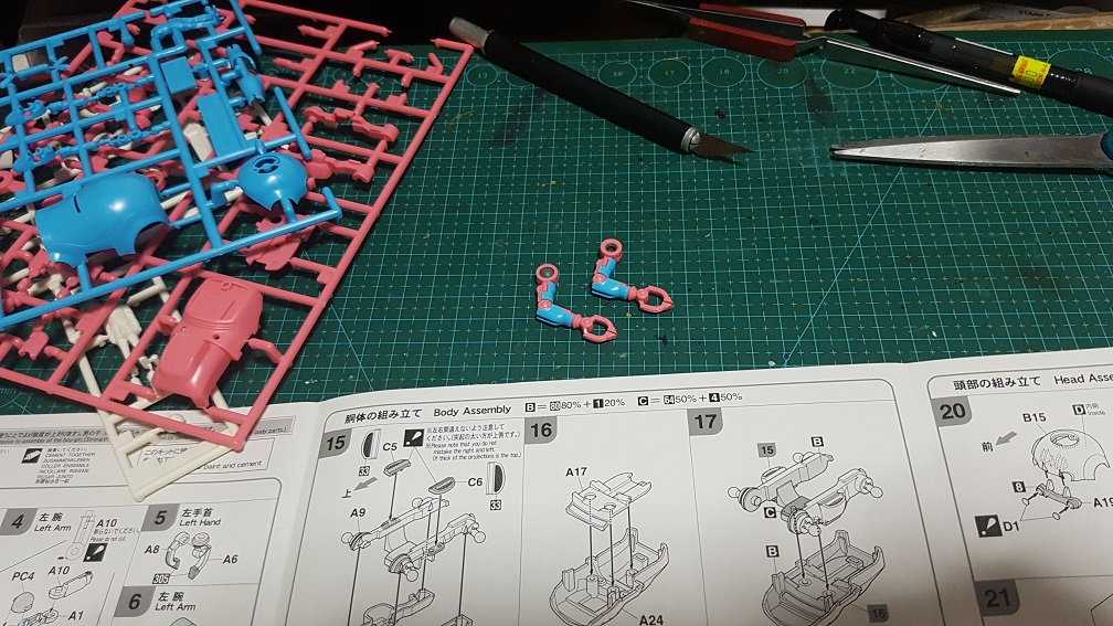
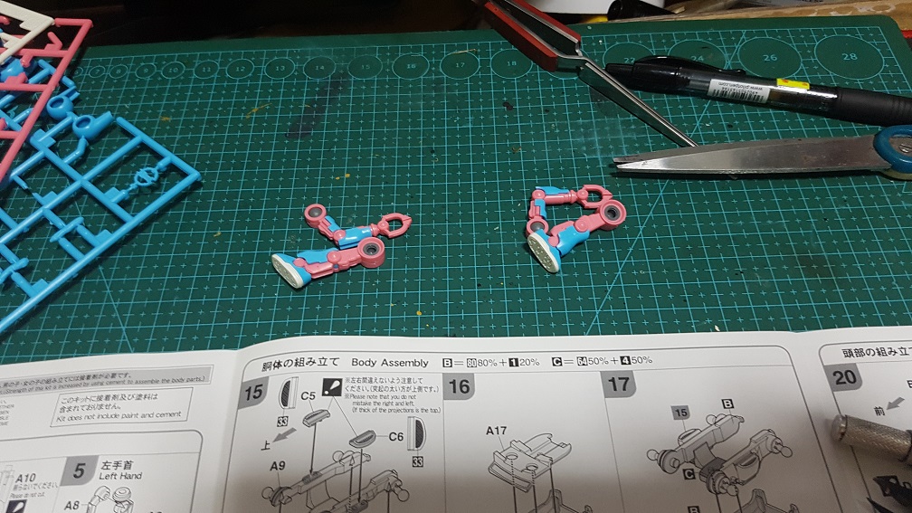
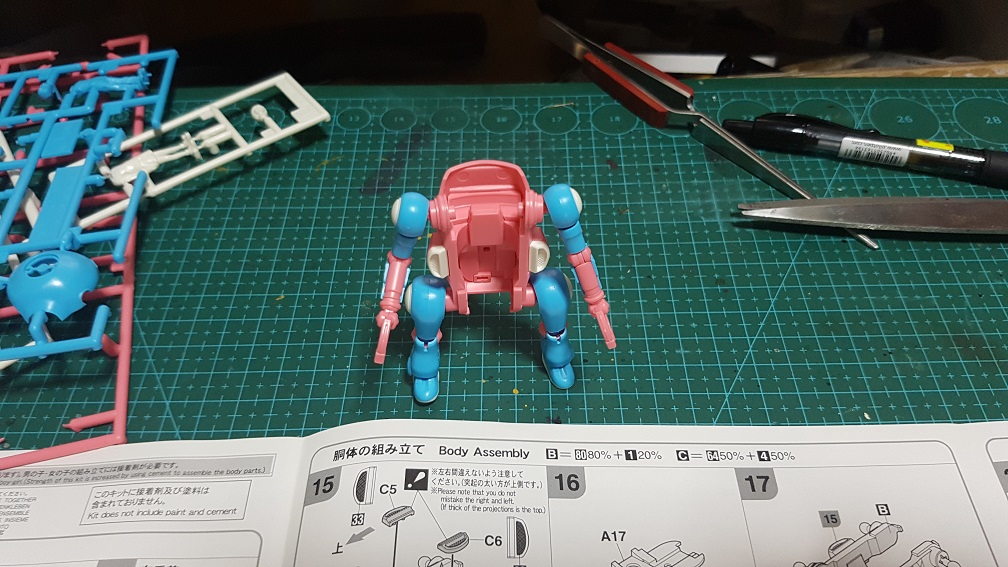
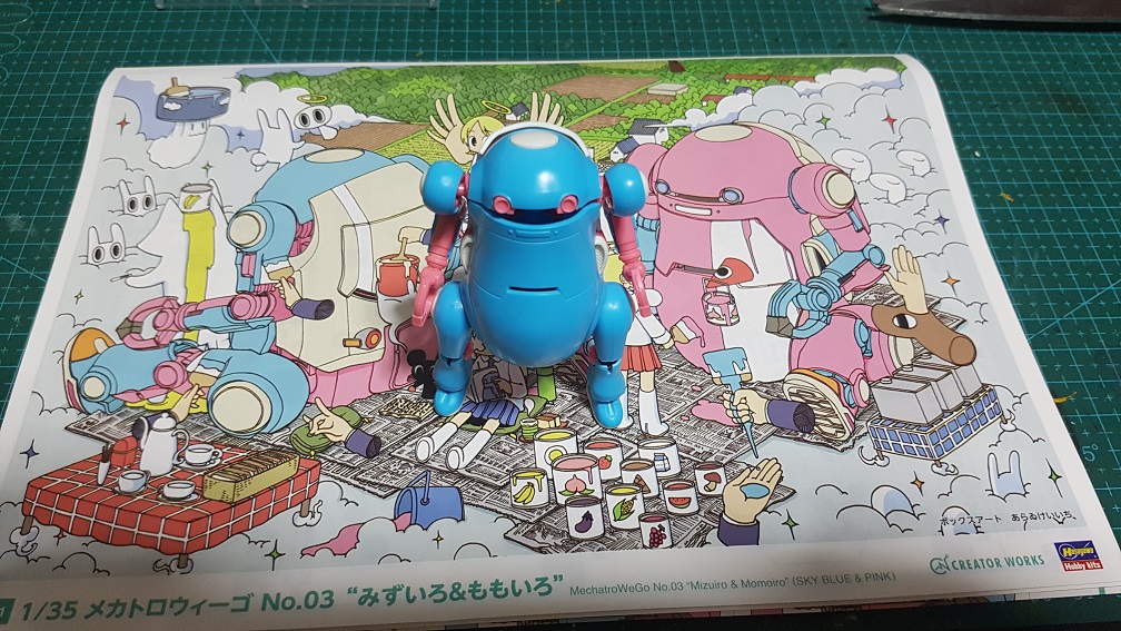
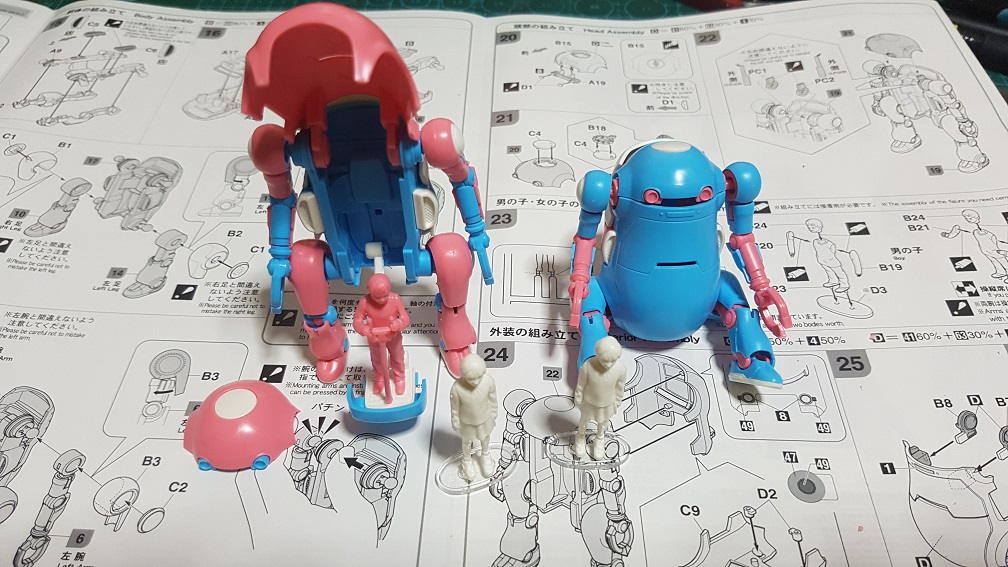
Plastic model building from the Japan Research Trip:
These are the show I watched in the past 2 weeks to get ideas for the robot personality, appearance concepts, and the overall world for O.U.R.S..
next gen:
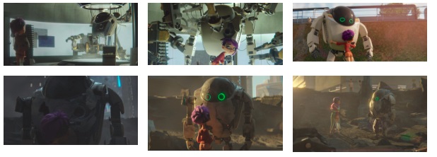
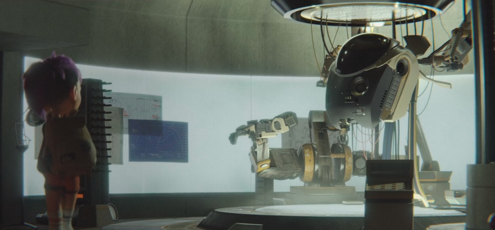
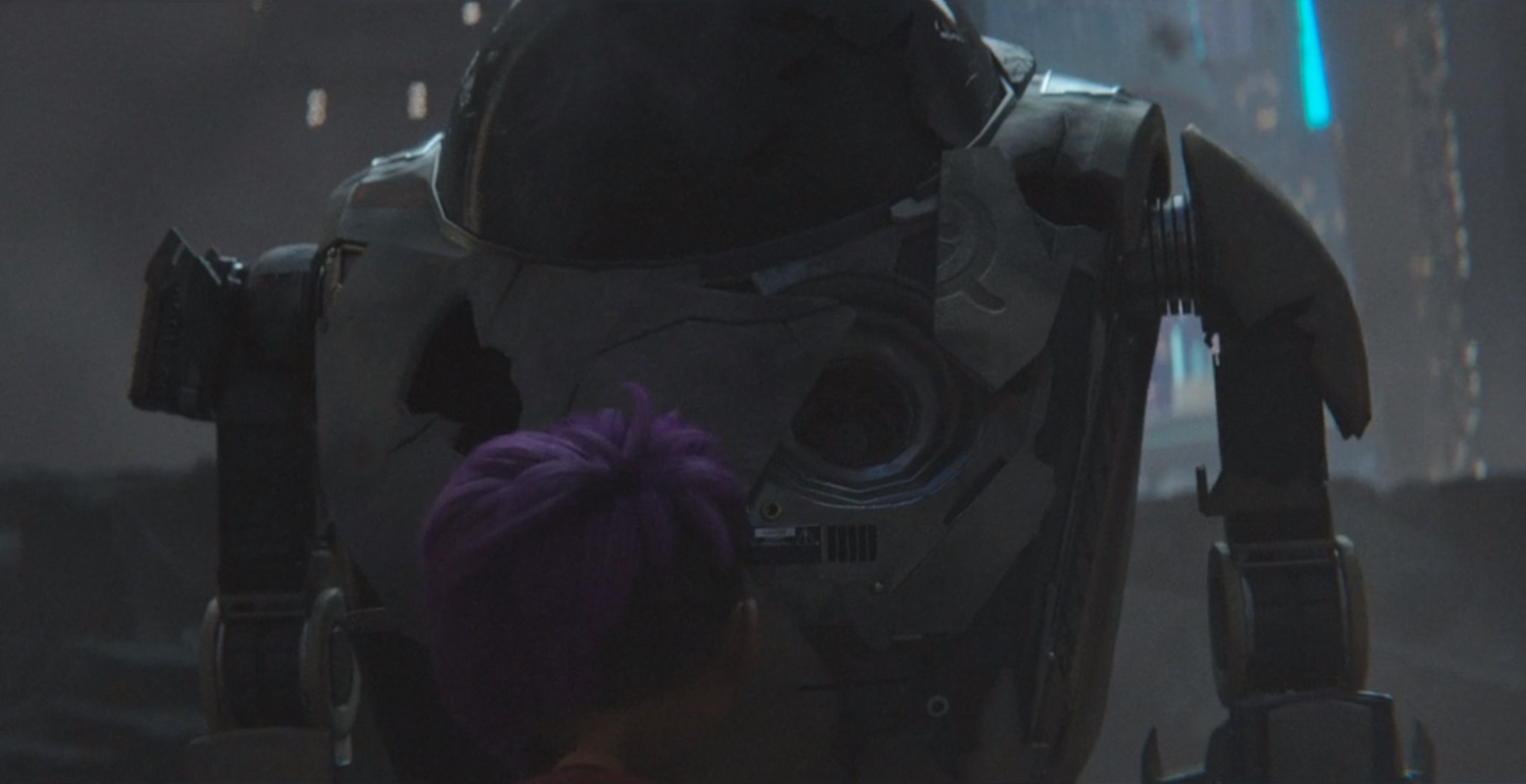
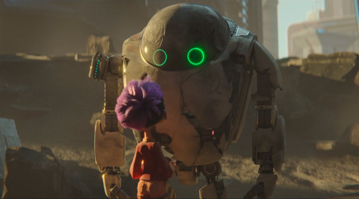
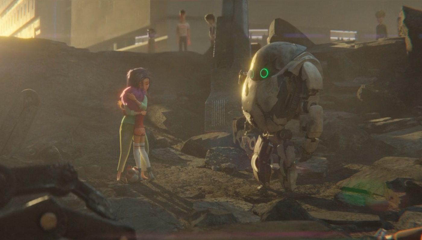
This is the nearest concept to what I have in mind, from the robot characteristic, appearance, to the overall concept. the Lab scene, the destroyed appearance is what i could reference on and I really like it.
Final space:
The personality of KVN(Kevin, the round robot) of this show got some really interesting personality, it is really irritating and have some sense of self realization that it is easily replaceable was really cool.
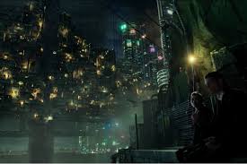
altered carbon:
watched to get a general sense of a cyberpunk theme(which is the world O.U.R.S was placed in) really cool technological stuffs here and the city was really well made.
dragon pilot:
Dragon + Robot, quite cool, except for the fact that the anime was good, there was nothing much for me to reference here.
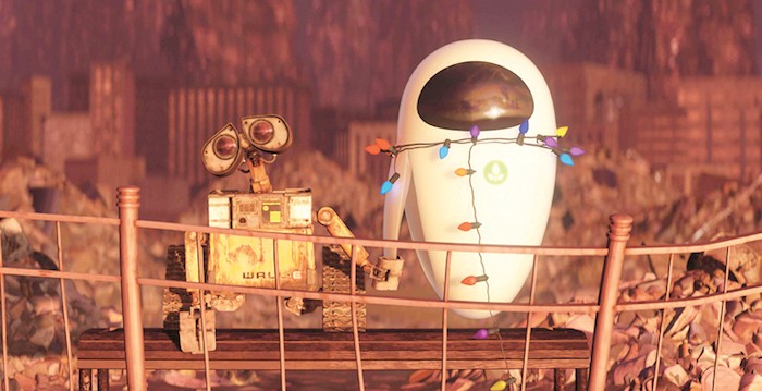
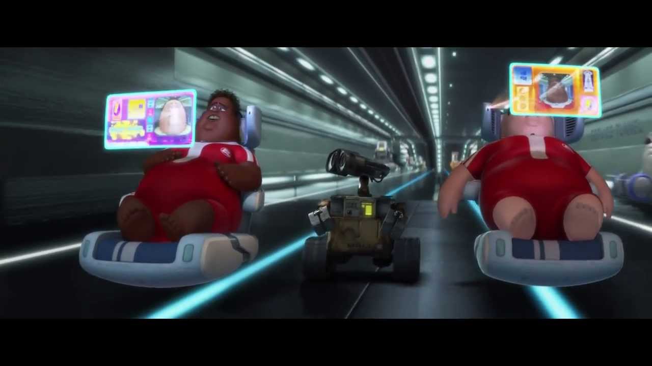
Wall E:
classic, robotic sound can create emotions too, simple movement and eye from the robot could say alot.
Real Steel:
it is just an action movie with robot, nothing much here.
current Art Direction for explorer 27:
Friendly, empathy, not industry looking, not intimidating.
BY 26 OCT :
unity + touchscreen control master arduino
read book (I robot – Isaac Asimov)
By 9th nov:
drawing for concept
lidar(maybe)
head model (maybe)
Further Research Done:
“Mobile Robot Planning to Seek Help with Spatially-Situated Tasks
Stephanie Rosenthal and Manuela Veloso
Computer Science Department
Carnegie Mellon University
Pittsburgh, PA 15213”
Adobe After Effect for the animations(I got my animation template online and edited it.)
Adobe Premiere Pro for converting the animation into GIF
Powerpoint slides for the slides.
Why use GIF for animation? Because a video in slides is not loopable and have too much constrains, so if I separate one animation into 2 GIF (Appearing and Looping) and use the “Animation- Appear” function in Powerpoint in a well-timed manner, I could create an illusion that it is looping.
That was how the slide was made! and I learn After effect for it because most of the animation i used in this slide could be applied in the UI of the robot (Remember i have a screen that needs User Interface, yes, thats the one.)
Also, The Lab coat i wore during the presentation was customized with the logo of OURS to have a more cohesive feel to the theme.
What had i learn in the presentation:
Antropomorphism in robotics
main issue in the fyp: Fake Ai -> Belivability -> Lost -> Antropomorphism
LEM Solaris (movie and book, george clooney) , I robot russian Stalker
During the process of adding digital to the analog version, there were more failure than success done throughout, let me start with these failures (and additional works I did which were not used in the end)
The unused Animations
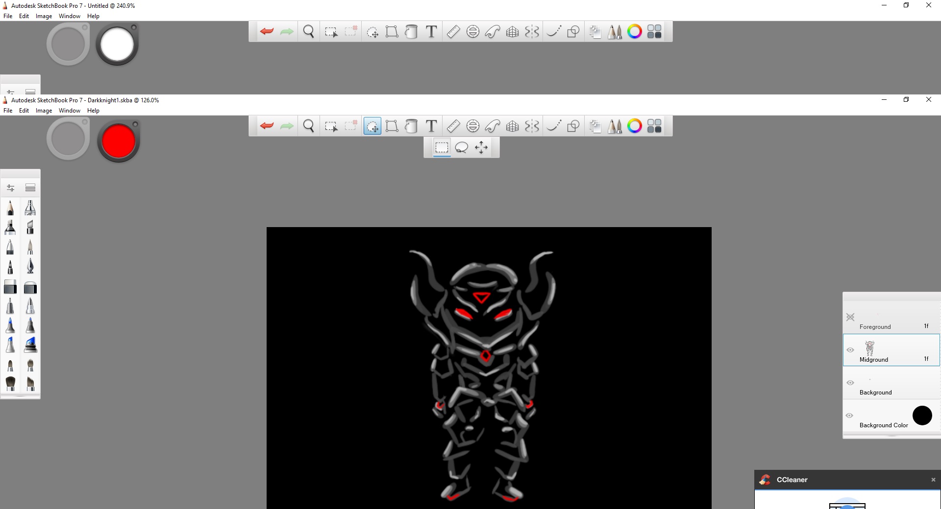
Right after the completion of the analog version, I thought of making a projection of animation from the back of the candles onto a sheet of translucent paper sticked behind the candle shelf, I tried to learn how to make an animation and so I asked my animation friends what program to use to do a simple animation and they suggested Autodesk Sketchbook, so I downloaded it.
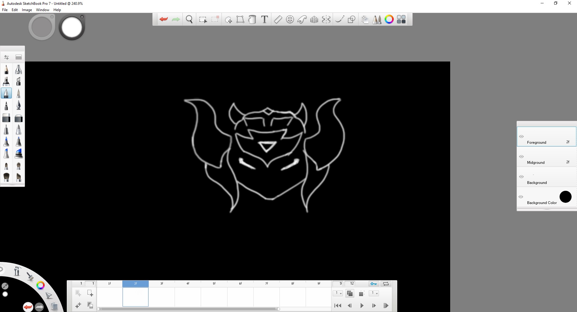
I started to draw the head supposed to be shine behind a candle that was unlit.
and slowly completes the overall
And I manage to make it move, although simple, this took around 7hours to make sinply it was the first time.
and this is the character that was supposed to be shined behind a lit candle, this is much faster, only took like 1 hour.
The Circuit that works,(or didn’t)
And then the Fairy light I bought from china arrived! I bought 220V fairylight because they are cheaper, and I did not expect them to be these problematic to deal with due to the dimming issue and also 220V = risky.
The light light up really well! they are 10M each and I’ve bought 6 rolls.
and then I cut off the wires
and rewire them to a Solid State Relay, I thought this would work really well as they are relays that dont have mechanical parts, so in theory, they could handle PWM for dimming….
and then I tested the connection,
and I tried adding PWM code to run the LED, It did not work as there was no dimming, all it did was full flash at faster rate. SO IN CONCLUSION, SOLID STATE RELAY IS FAST, BUT NOT FAST ENOUGH FOR PWM!
Since the SSR alone doesnt work, I thought of adding a capacitor to the circuit, as it will hold and release charge, it should smoothen the flashing rate? thats what I thought. In reality, the flashing of the LED is still really obvious so I cant use it too.
I also modeled and printed a case for the SSR as they are 220V, my common sense tells me to cover all exposed 220V metal parts as much as I could.
As the SSR and capacitor combo doesnt work, I thought of using a Mosfet to control the PWM of the 220V circuit… and my arduino blew off instantly after i turn on the 220V switch. yeah, maybe I wired them wrong, but I am not going to try it again as it instant killed my Arduino… one Arduino down, a few left to go….
So I wasnt expecting this to work, I did alot of research about using the super small resistor I have on a 220V circuit, and everything on the web said that I should not use it, but I thought I might as well try to see if it blows up or get heated up really quickly, at most i lose one resistor, I could definitely afford that! so… WOW TO MY SURPRISE, IT WORKED! THE RESISTOR DOESNT HEAT UP!
AND 1M OHM RESISTOR MAKES IT DIMMER!!! SO YEP. IT WORKED LIKE THIS IN THE END. all those expensive components I bought couldn’t be compared to these small resistors… ALL HAIL RESISTORSSS
so I researched about how to calculate the resistance of the resistor, the more parallel there are, the lower resistance = brighter, so I could do a combination of brightness from a 2M( 2*1M in series), 1.5M(1M and 500k in series), 1M, 680K, 91K. With these numbers, i could do a huge variety of resistance to dim the light(like for example, 2M and 1.5M in parallel gives a net resistance of 857k) , i just need to connect these to the SSR(normal relay could work but since i have these already) and select the path to open to create the parallel circuit and hence controlling the resistance to the 220V circuit.
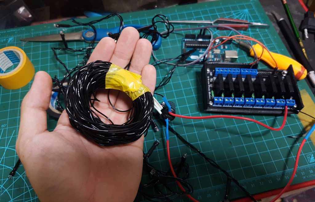
I’ve notice that there are 5 wires in each strip of LED, and only 3 is requires, and I also dont need to chain these 10M rolls anyway, so I decided to savage these wires in case I needed them afterwards.
and although it seemed simple, it took some time as there are a total of 60m.
I am really glad that i savaged these wires, as just nice Makoto needed this so all time savaging was really well spent!
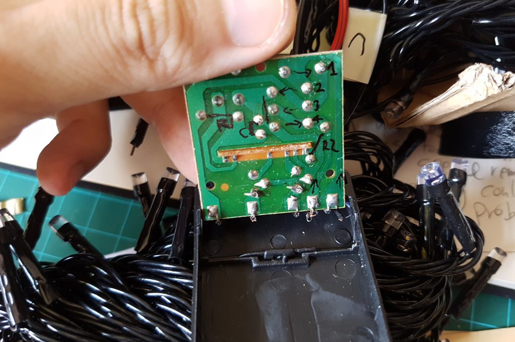
The original adapter and controller have some problem with it as it will automatically switch mode, sometimes to flicker and such, which I just want to have constant brightness controlled through my arduino, so I decided to remove the chip within it by replacing this circuit.
so I tried to understand how this works and mapped it out
and then I re-soldered it to the circuit board
and in the end, this one doesnt work so I found 1 adapter for this kind of LED light and use that instead, which works!
The additions to my “Dark Room”
I’ve picked up this from near my house and thought that I could build a legit door out of it, so I did, and in the end i removed the wooden piece I screwed in and made it a folding door, I also added magnet to the door so that it will stay closed to reduce light leak into the room.
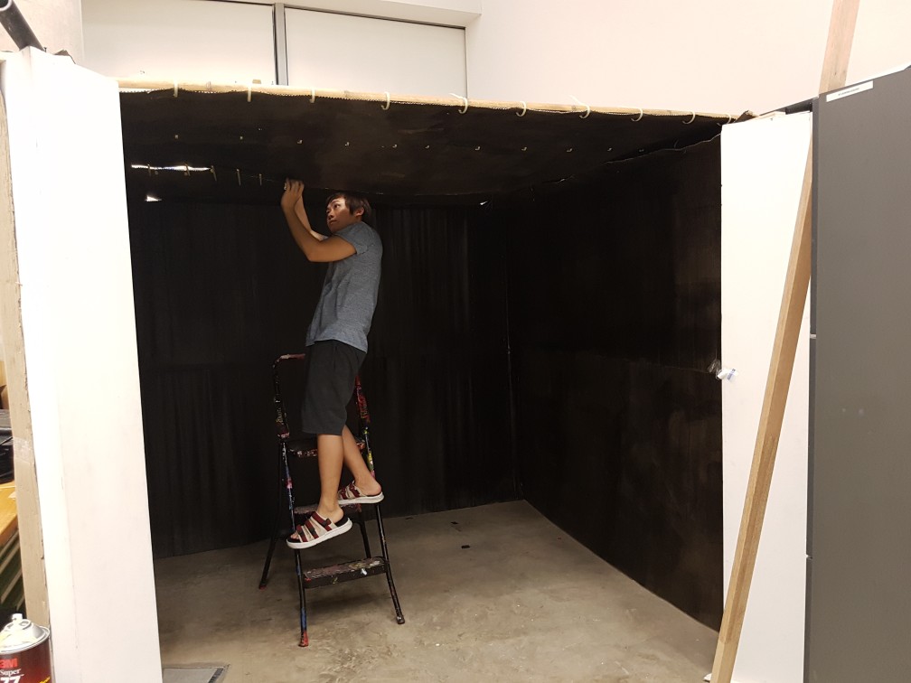
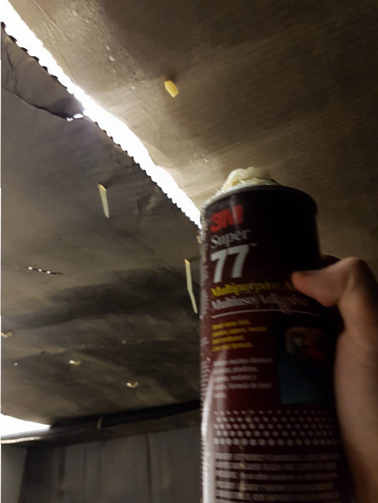
attaching the LED dtrips to the roof of my “Dark Room” is a big problem as the roof is too big for me to puncture a zip tie through it (i can poke one end through, but can’t poke it back to complete a loop), and tape is too not reliable for my project as i need to have it on for atleast a week, so I’ve use a lighter to burn a needle and bend it slowly to a U shape so that I could pierce it and bring it back to sew the LED strip onto the roof, and just the sewing of the LED took 2 days to complete, because I have to carefully organize where I am attaching each point so that it does not go into the line of sight of the camera I will use to sense the candles.
slowly but surely, I attached these LEDS to the roof and wall of the “Dark Room”
and I tried lighting up, the best thing about suspending the LEDs using a thread is that not only it will create a better illusion of stars, it will also prevent a fire hazard as there is a much lesser chance that any wire(220V) will touch the cardboard and setup a fire. so I am sure of the safety of this project.
Coding is a nightmare
as there are 297 candles, the coding to split each candle was simple but tedious, I am sure there are better ways to do thing, but the downside of using max msp was that the exact function to do things the better ways is really difficult to find, so… my mindset was “If I only know “IF”, I can also do unlimited amount of task, “IF” is as powerful as Hercules.” so… I had “IFs” my way through this project, literally. (just to be clear, I tried to find a better ways, and though I found them, but in the end it either doesn’t work or crashed my max msp.)
the main patch consist of Jit Grab to get information from the webcam, a lens distortion corrector as I am using a 150 degree webcam, a crop to crop away all details which i dont need and to pixilate the average brightness within a certain region to a bigger area(to see is the camera capture a bright object within a certain area which can be used to see if the candles were lighted up indivitually or not.
the jit.cell which shows the numbers in every squares (33*9), which is the amount of candles I have
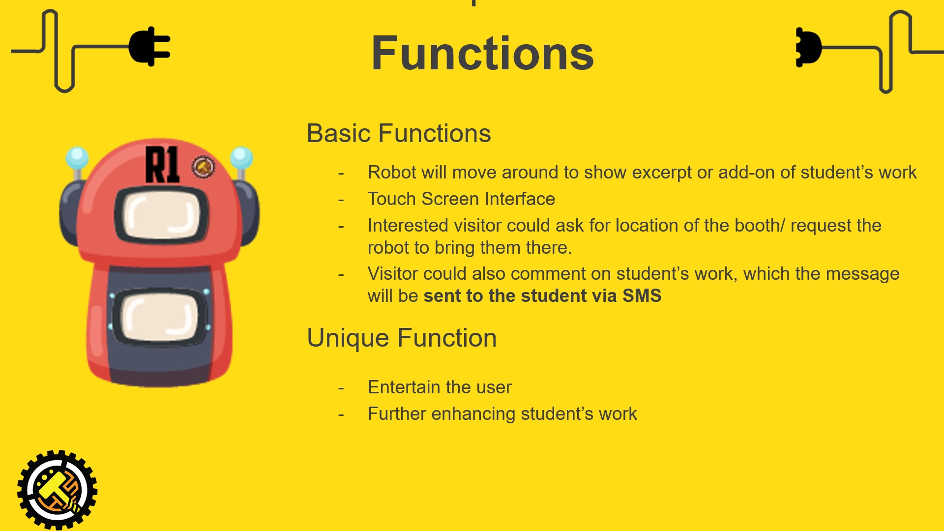
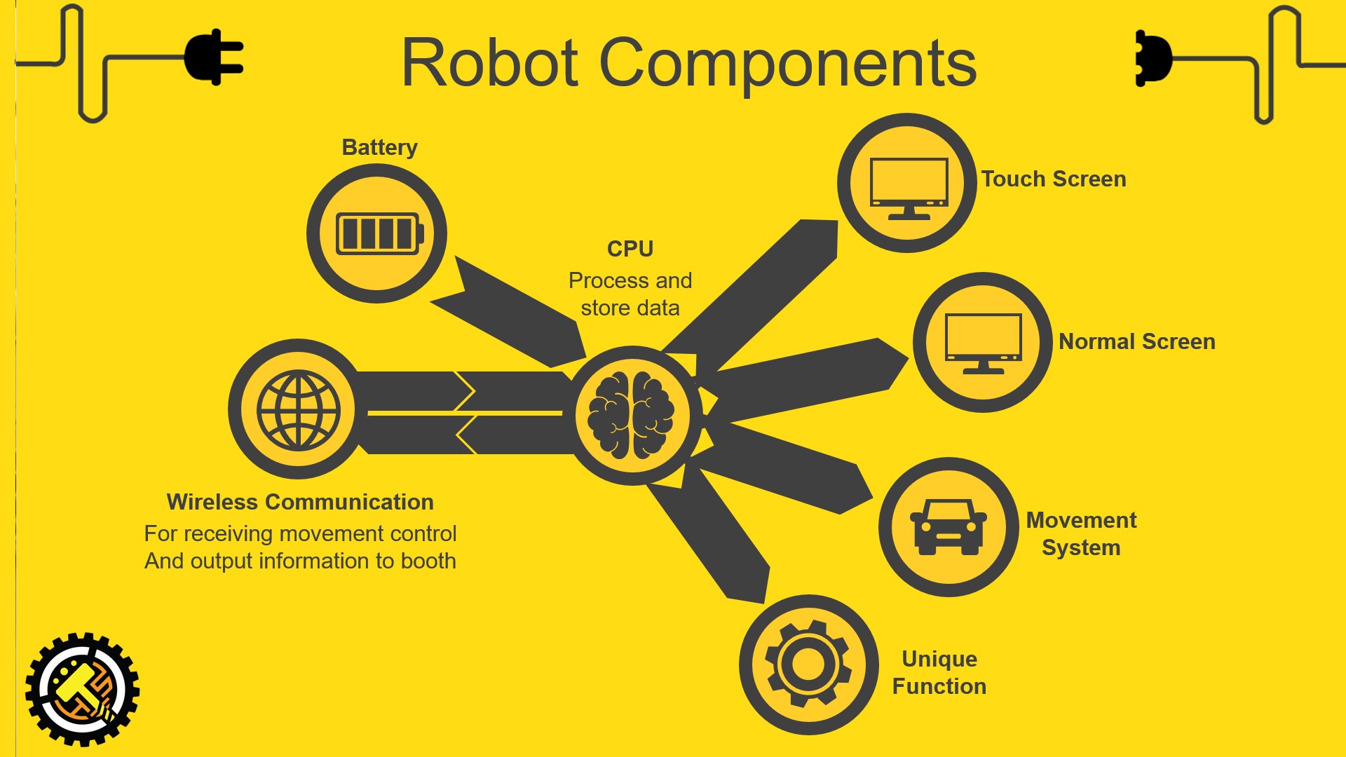
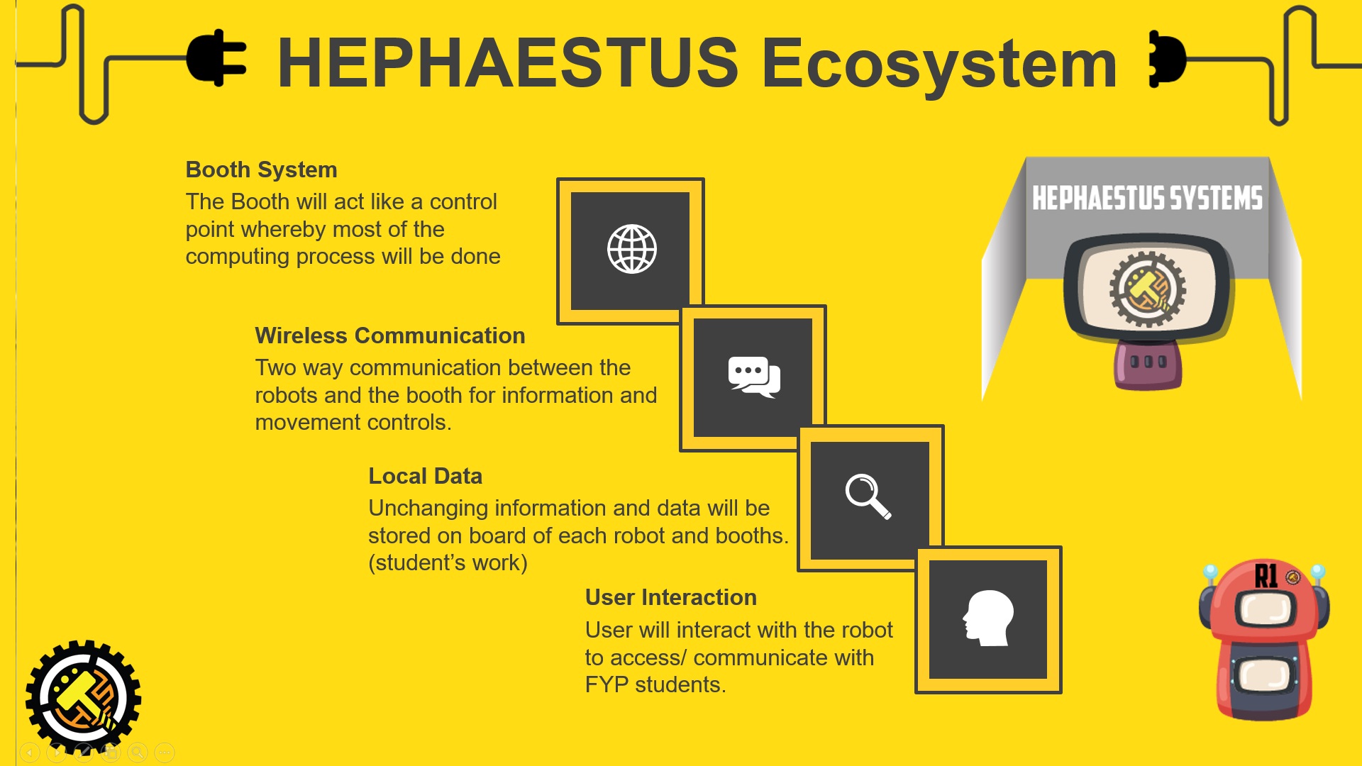
Hephaestus system is a set of 3 roaming robots and a booth, these robots will be specially designed with different appearance and function to provide addition showcase platform and information of all the FYP students (except for me), visitors will not get any information of me from these robots. Only the booth will have information of me because, really, I have to find some place to put my name card. And it is kind of cool for the visitor to realize by themselves that the robots is a work of a student. Another reason for the robots not to show my work is to prevent conflict with my peers, since my robot will be walking in other major’s “territory”, it is simply not nice to broadcast my own project.
Imagine one day when you are lying on your bed and receive a SMS telling you that your FYP project is awesome? how great is that?
Imagine what can the system do for product design student if there is holographic display on one of the robot? You will see the student’s information on the main screen and the student’s work in hologram?
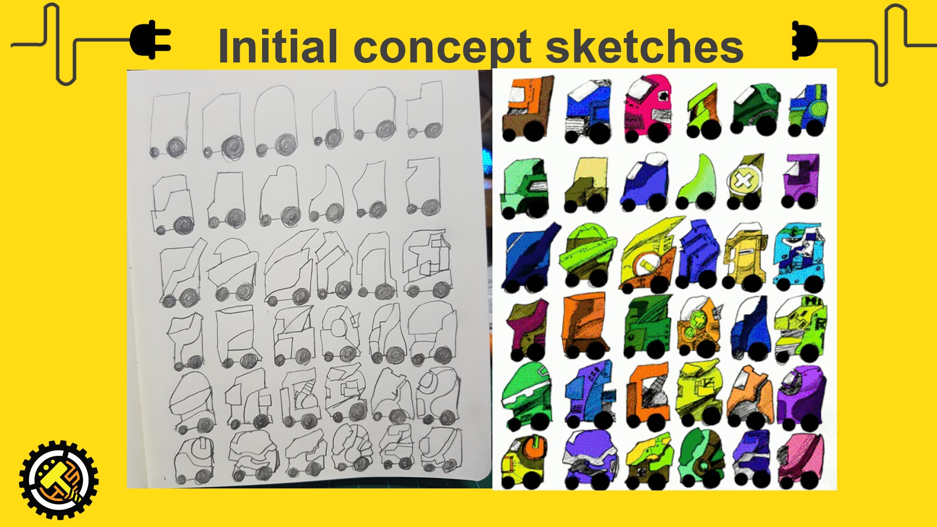
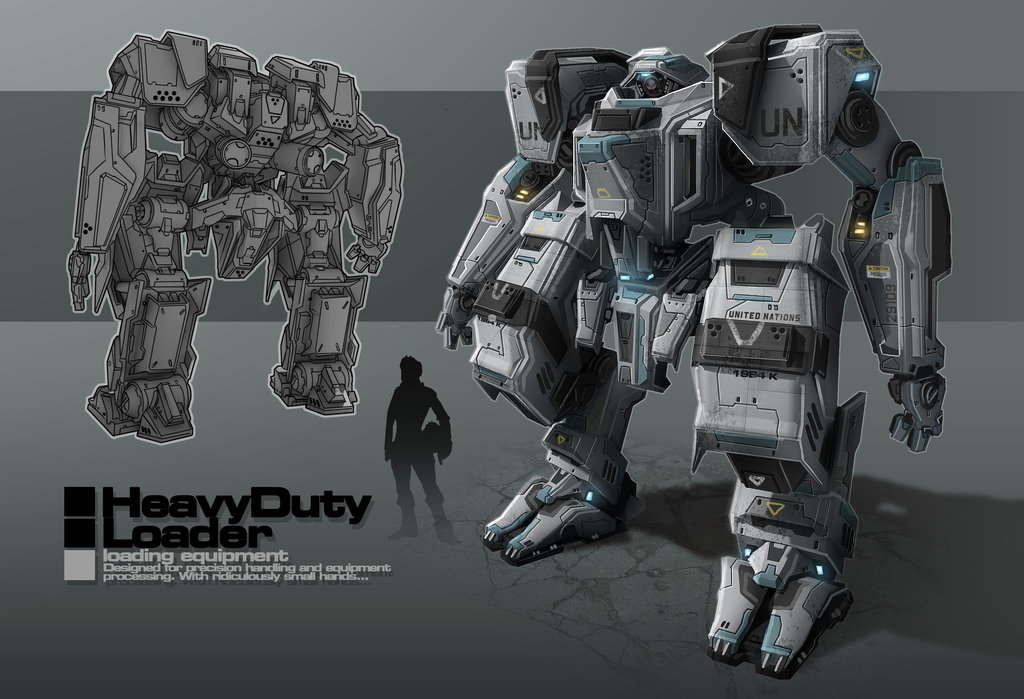
Slightly more detailed drawing of the one that I like the most out of the 36. this will be the rough gauge of the size of the robot
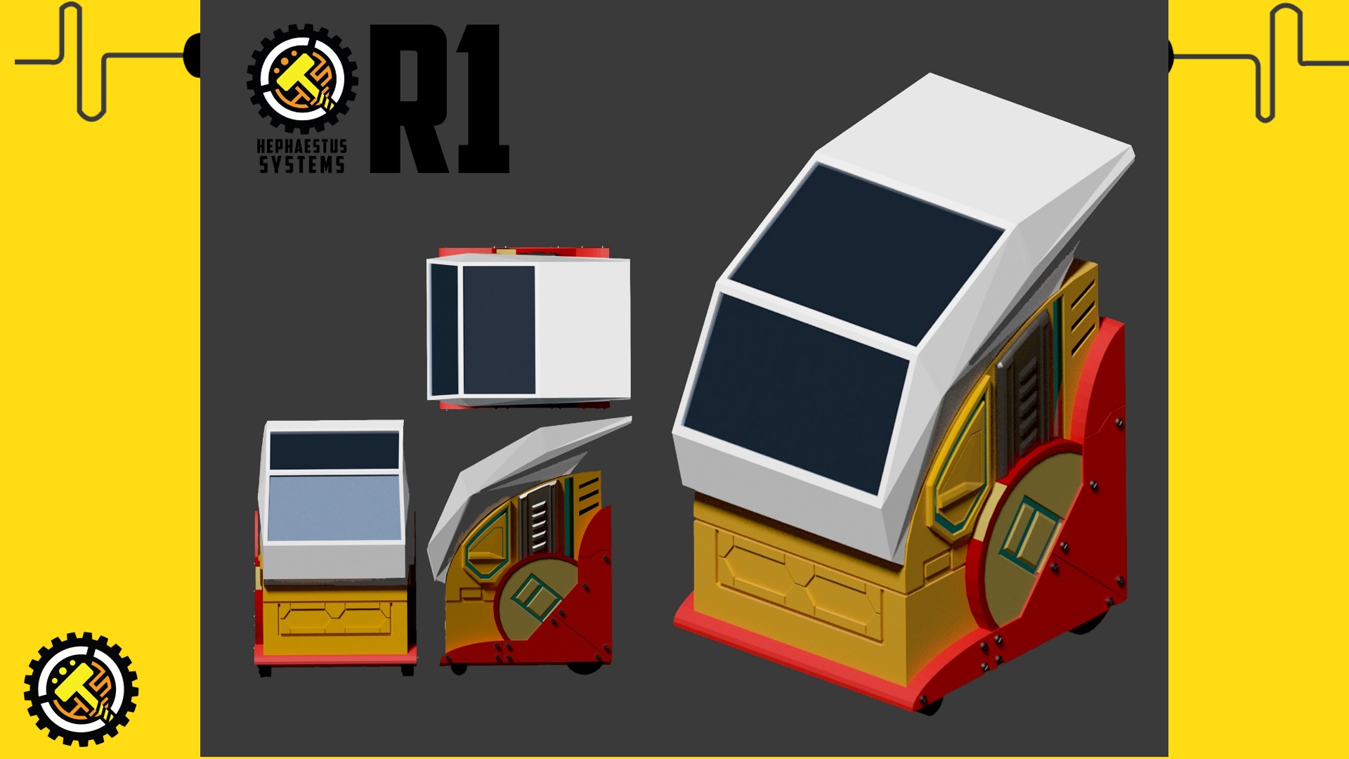
The final robot will probably not be this, but this is a good gauge to show the overall style of the robot which I will be making, not those typical looking or DIY homemade robots.
show the remote control proof of concept i made.
Computing done in the booth system as it will be connected to power supply and heat will be dissipated more efficiently than in the robots. Current location of the robot and movement control will be sent from the booth, user input and message will be sent from the robots to the booth.
Intended recipient and message from user will be transferred from the robot system to the booth through wireless (Bluetooth or Wifi), Booth receive the message, encode it with the recipient’s phone number into the GSM module and send the message through a prepaid simcard.
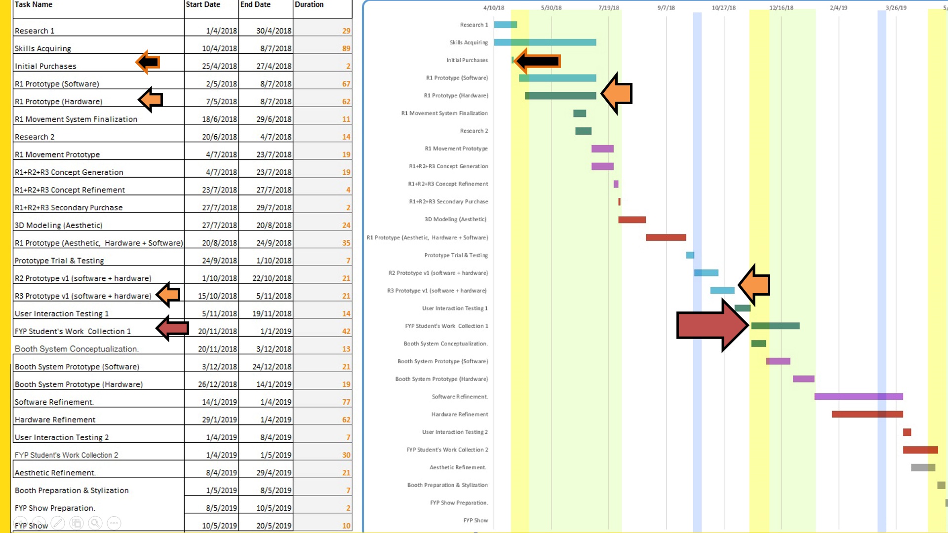
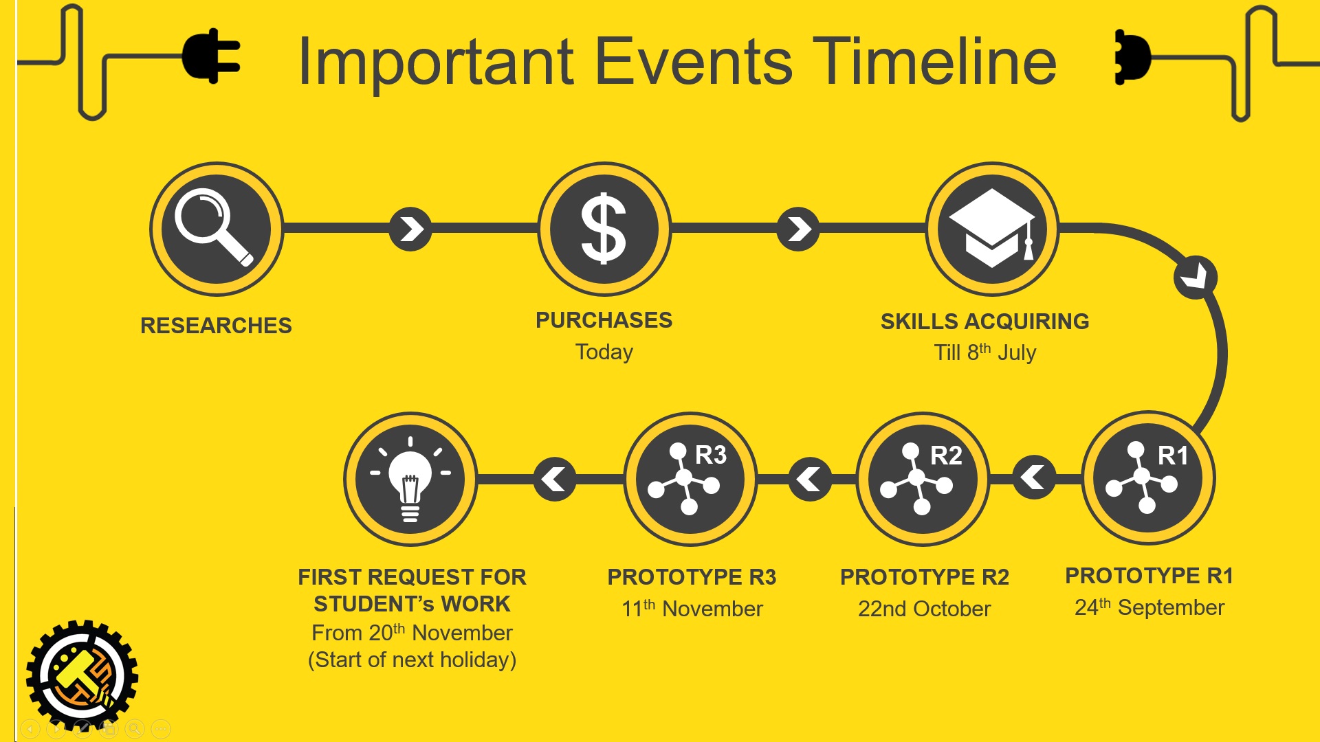
Skills Acquiring and Prototype R1 goes hand in hand, I will learn while doing and do while learning.
As of now, there are many skills which is essential for me to achieve this project but I don’t know, so I will be learning them. Blender is a 3D modeling software, it is really powerful and the best part is that it is free, the downside is the learning curve is really steep.
continuation from the previous part 2 post with some new ideas after the talk about the past FYP showcase from Assoc Prof Laura Miotto, I’ve been inspired to do something that focuses solely on the showcase, since the showcase will mark the end ADM life of all current year 3, I would like to do something for many of the peers that would enhance student’s FYP showcase capability as well as the visitor’s experience of the visit.
As the founder of Kimchi and Chips, Elliot Woods asked during the Emergent Visions Symposium,
“What is the work that only I can make?”
This question hit me like Tiger Woods golf clubbed me in the head…
Yes, what is the work that only I can make in this coming FYP showcase?
back to my first post, I’ve already know what my strength is at this point of time, I would really want my FYP to have an impact on others, why not use my strength into making other’s FYP presentation to potentially having slightly more possibility? Wouldn’t that be great?!
so, this will be an idea which I know that I would enjoy spending a year to complete.
A set of robots(3 to 6) that will display student’s work in complementary of their booth where visitor could get more information(project info/booth location).
Just imagine, every student have their booth while a robot moving around in the FYP show displaying their project on its screen, when a visitor saw it on the screen, got interested and wanted to see the booth, they simply click a “Bring me to this booth” button and the robot will do so. How much more potential exposure will that bring to that student?
And on another aspect viewing this project, what will be realer than an actual application of an FYP project during the FYP show? What the visitor sees is what was actually made specially for that FYP show, if it doesn’t work or spoiled halfway, it simply meant that I did not plan well/have a backup or do a good enough job but there will not be an imaginative scenario where “This FYP was supposed to work in another location” *I am not saying that that kind of project isn’t good, but just what I would not like to do*
Project Brief ver.1-
To design a set of Robots that have the ability to move around while avoiding people/obstacles during the FYP show. The purpose of the Robots is to expand the presentation possibility of student’s project while enhancing the experiences of the visitors. Safety of the people around the robot should be of the utmost importance and under no circumstances whereby injuries caused by the robot should happens.
Project Specification Ver.1 –
Each Robot should have a minimum battery life of 6 hours on single charge.
Every Robot designed should be unique and serves different function.
The Robots should be designed with ease of maintenance system that allows ad hoc repair.
The interface on every Robot will be touchscreen enabled to suit the behavioral characteristic of the targeted user. ( young adult of developed country)
Network between Robots and a Central Hub should be setup to enable a smooth flow of communication and for controls during the exhibition.
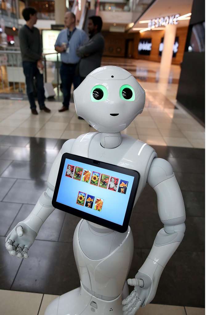
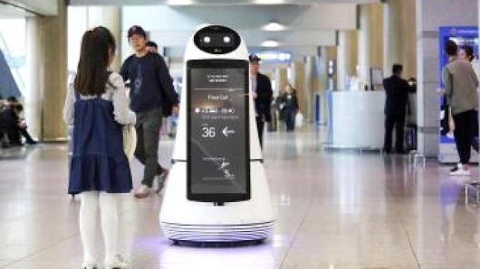
Similar Project :
Although it will be really hard to do so, but I aimed to complete a project of this standard but the task which my robot will do is much simpler.
Moodboard:
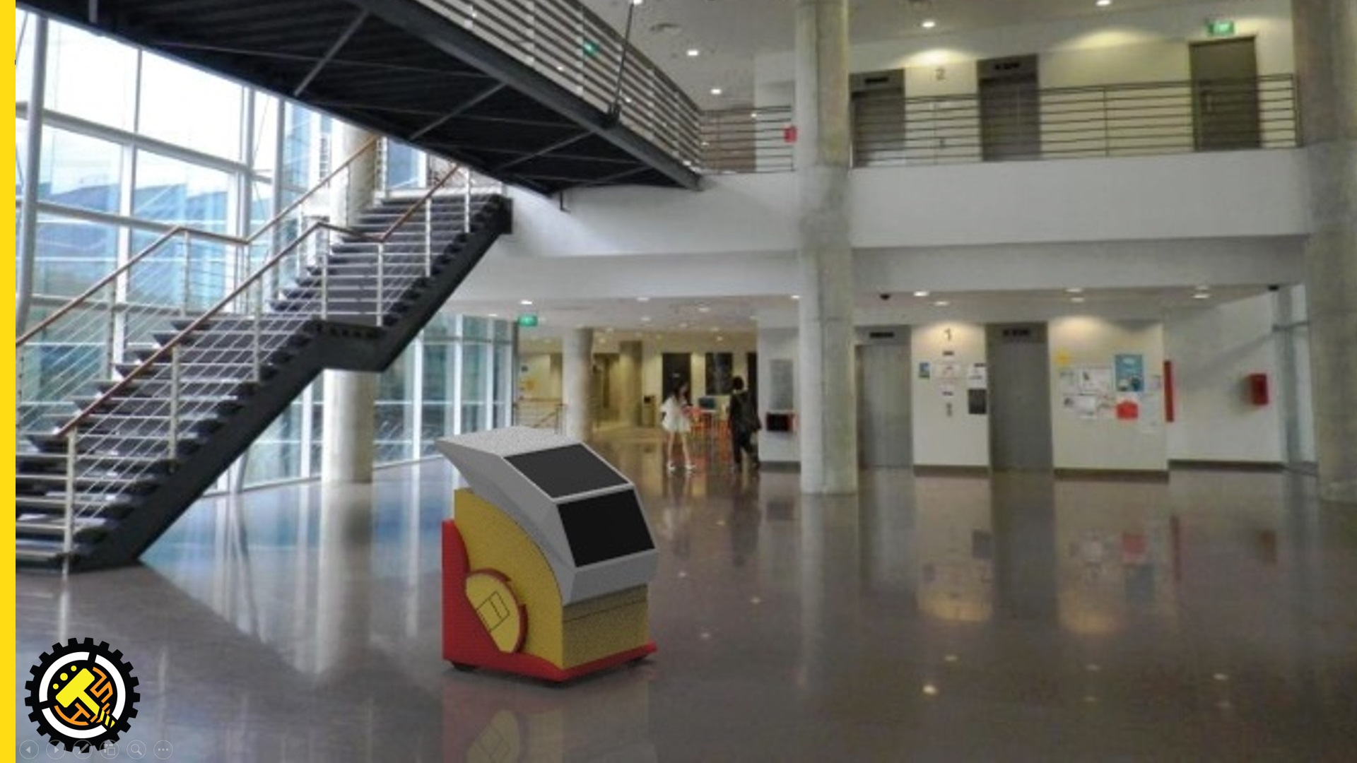
this will probably a good gauge as a robot size which i will build.
of course, the screen wont be so big as the price would be expensive.
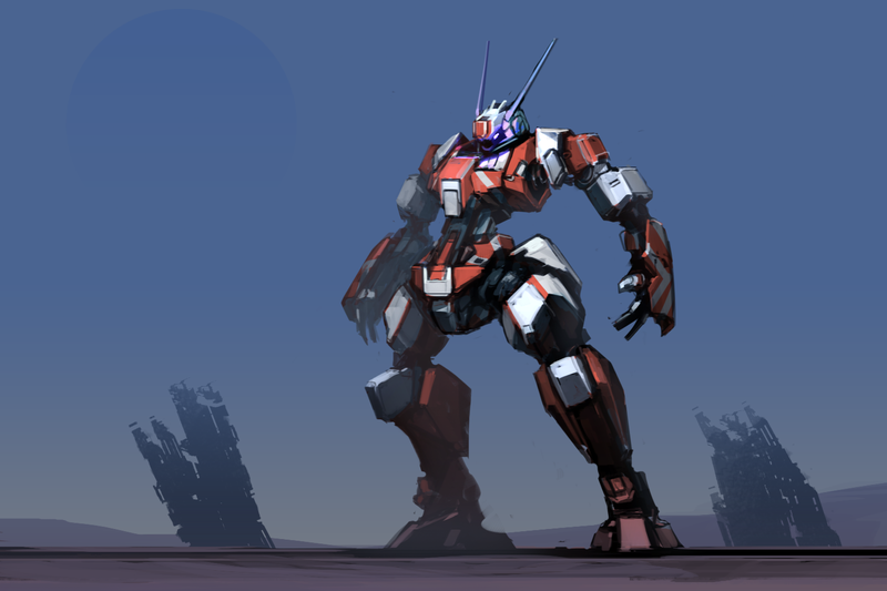
468_999 by ksenolog.
I like the colour scheme of this type of robots,
bot by operion.
Although it is rather dark here, but the top simplicity is rather cool.
bot concept design by chriss2d.
I might build a similar robot like this minus the limbs.
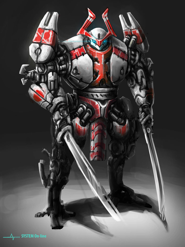
samurai bot by andynd.
Colour scheme.
catsbot by trudsss.
colour scheme and friendliness
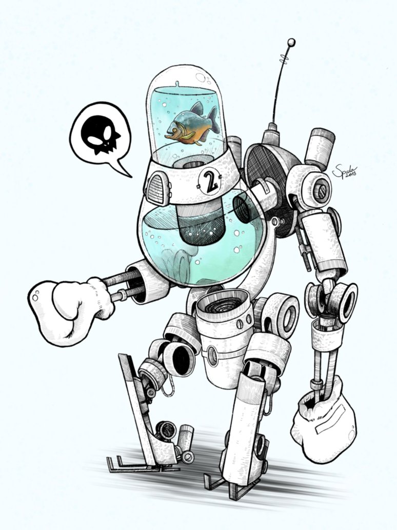
fishboxerbot by hubertspala.
unique design that is out of the box.
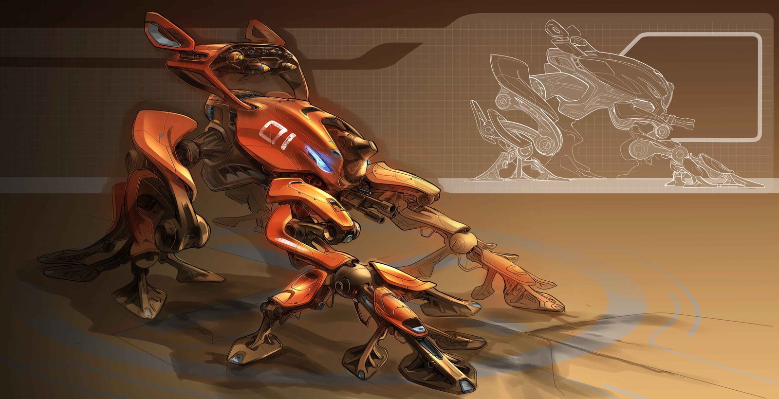
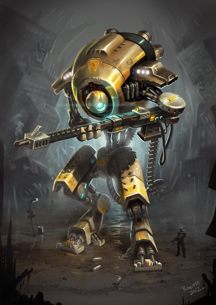
giga bot concept by ultimatemaverickx.
colour scheme, + shape
hammy the hammer head by andynd.
I really like this cute robot and simple shape
hdri bot by ethan.
Shape.
kuning bot by adry53.
Colour scheme
red boy by adry53.
Colour Scheme
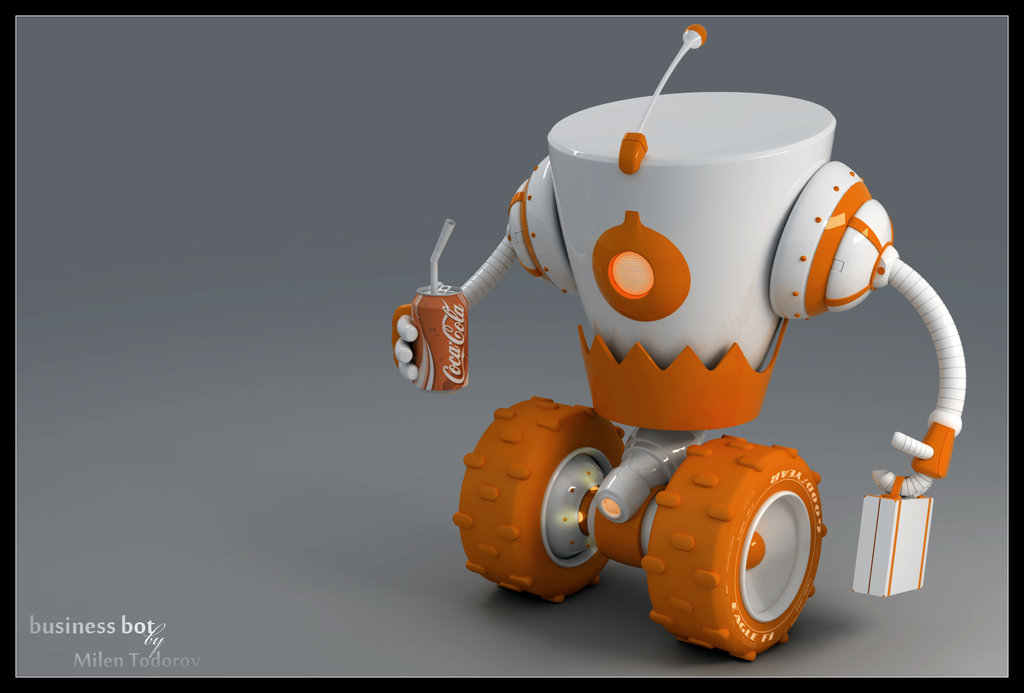
business bot by milenplus.
Colour scheme + the overall friendliness aspect seemed similar to what I have in mind.
mean frog by glaaarg.
cool robot like this might be nice too.
mech 3 by astrokevin.
overall presentation of a poster-like layout will be good on my FYP booth,
mech by nemanjas.
mech suit by flyingdebris.
Overall shape and details minus the limbs
mekachu by trudsss.
Colour scheme and cuteness.
mobile memory unit by tehan.
I like this and the idea in which the walking camera is a “Mobile Memory Unit”
remember to by inkgummi.
overall feeling + the screen head is nice.
robot by ahmadturk.
Colour scheme+ details + shape.
sir crow by trudsss.
Cuteness and the robotic like armor with organic head.
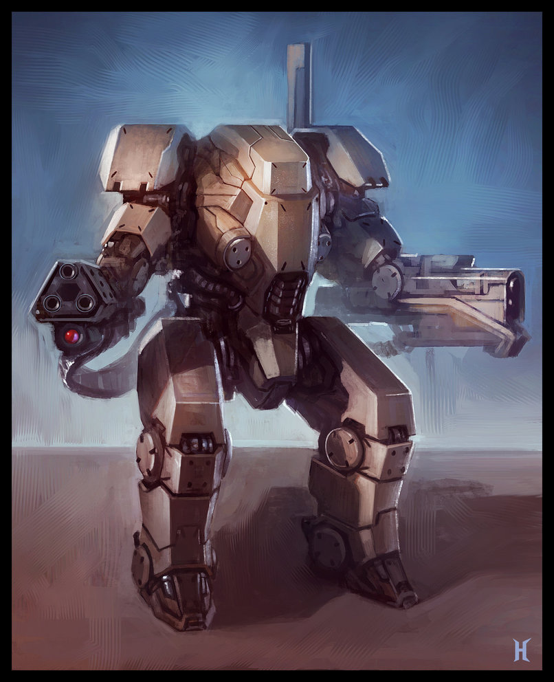
sniper bob by boxer18.
details + colour scheme.
Computational System Research:
There were many considerations made for this aspect of the project, firstly, the Cost and Value Analysis of the system must be made, of course, if money isn’t a problem, then this part would be really easy as I will just get the suitable parts which I need for the FYP, but sadly that isn’t the case… Money is a problem in FYP.
So, how can I maximize the output of my project by using the minimum amount of money? I have to also consider about how strong/fast the system is, and how would I like to have the user interface (touch screen) to be incorporated into the system.
These are the types of computation system which might be possible for my project at reasonable price –
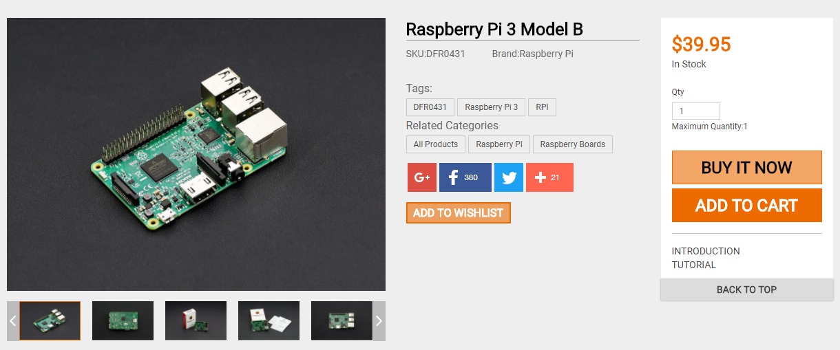
Raspberry Pi 3 –
This is the latest Raspberry Pi 3. It features a 1.2GHz 64-bit quad-core ARMv8 CPU with 802.11n Wireless LAN and Bluetooth 4.1. Like Raspberry Pi 2, it also has 1GB RAM,4 USB ports,40 GPIO pins,Full HDMI port and Ethernet port. This third generation Pi is an excellent tool for hackers, makers and educators because of its small footprint, low power consumption, and low price.
Pi 3 comes with build in WIFI system so that would save me about $30 for WIFI module, output of screen is easy to setup(like a normal computer), runs on Linux system, which I have a slight experience on and as a bonus, I own one of this so that would save me some money too.
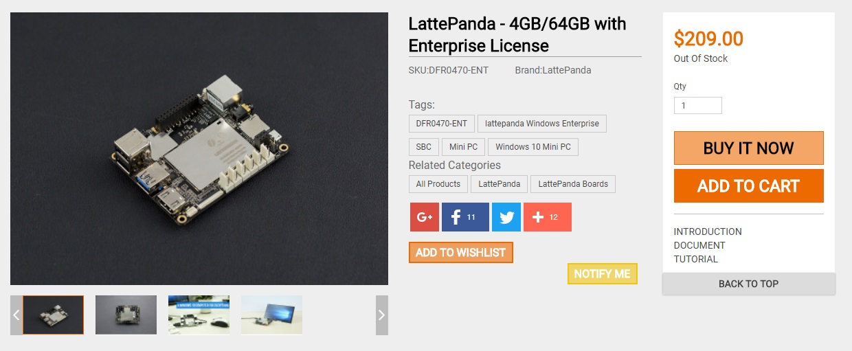
Latte Panda –
A LattePanda is a complete Windows 10 single board computer. It has everything a regular PC has and can do anything that a regular PC does. It is compatible with almost every gadget likw printers, joysticks, cameras and more. Any peripherals that work on PC will work on a LattePanda.
In terms of processing strength, completely overpowered Raspberry Pi 3, the price is however much steeper than Pi 3, also as an added bonus, I already own a Lattepanda and I would rather work on Lattepanda over Raspberry Pi as it runs on Windows system and that would save a huge amount of time for me, plus overall it is much faster at processing video and even runs Max MSP(a programming software) which is what I will probably be using. I am sure Latte Panda will be more responsive than Raspberry Pi 3 at the cost of more $$.
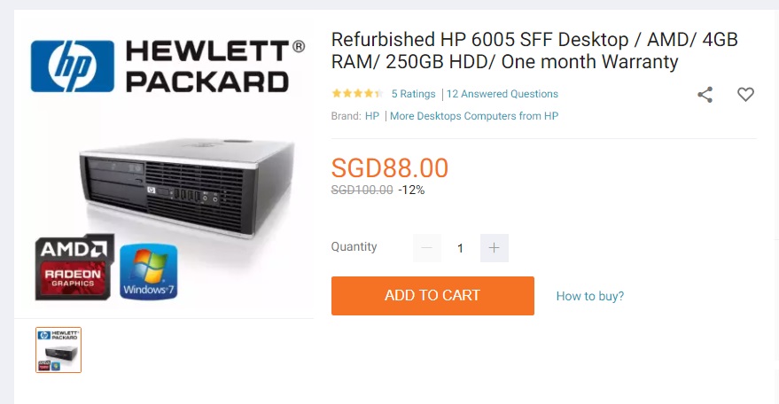
Cheap Desktop CPU –
Yes, I praised so much about Lattepanda, but the cheap CPU nowadays is already cheaper than a LattePanda, although bigger,heavier and more power hungry, it is way cheaper than a Lattepanda at relatively same processing power and also, a cheap CPU usually comes with Internal HDD(atleast 128GB) while Lattepanda only has a mere 64GB(minus operating system installed, leaving about 40GB). Best part, Desktop CPU comes with built-in cooling fan, which overheating is a problem for Lattepanda.
*REFURBISH is the word here hence the cheap price*
since I don’t really need a brand new computer to get the job done. This is the normal sized CPU, which is rather big but I am sure it is small enough to be build into a robot.
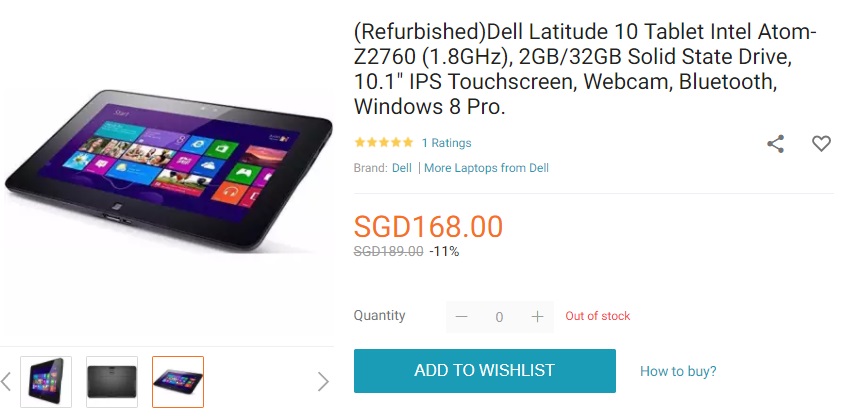
Second handed/refurb touchscreen laptop –
For me, I think that this is the best system i could think of for now which I will need, firstly, touchscreen laptop meant that I do not need to purchase another separate touchscreen(which is usually really expensive) secondly, it comes with all the benefit of a CPU like cooling fan and such, also, laptop have a additional battery which reduce the load of the power supply, like if the main power supply ran out, there will still be time for the system to send out notification to the control system which then battery could be replaced. lastly, laptop will be slightly lighter and uses lesser power in comparison to a CPU, which make it really good over a normal CPU.
These are really good deal I think, I have been also browsing on carousell to find cheap and well condition touchscreen laptops, will update when I found some.
By having a computer doesn’t meant that this project will work, of course, what I am going to do on the computer is all that matter.
Since I don’t have sufficient knowledge in programming for windows system or app, so I also looked up for some online courses which I think I may follow during the holiday.
If I were to use a car battery, I would get the deep cycle/marine battery as it is made for continuous discharge when connected to my computer within the robot/motors.
66 Meters Apart is a project that explores the disruptions in the train of thought when a speaker is articulating their words, as our brain functioned as it should, we’ve forgotten how complex the brain are in these almost instantaneous real time processing of information that we sensed. By using 66 Meters Apart, user will have personal experience of these disruptions within our thought and notice how easily it is to distract our focus even from simple task like reading out loud a few sentences.
The 66 meters refers to the metaphorical distance created between the mouth and the ear through digital latency of 200ms, which is the time for sound to travel approximately 66 meters. As we hear our own voice through bone conduction from our vocal tract to our ear (which is much faster than the speed in which sound travel in air of the same distance), the physical latency it took to hear ourselves speaking is almost instantaneous and we were accustomed to this. By introducing a 200ms latency of us hearing our own voice, it could greatly impede our concentration in thinking as well as speaking in most of us.
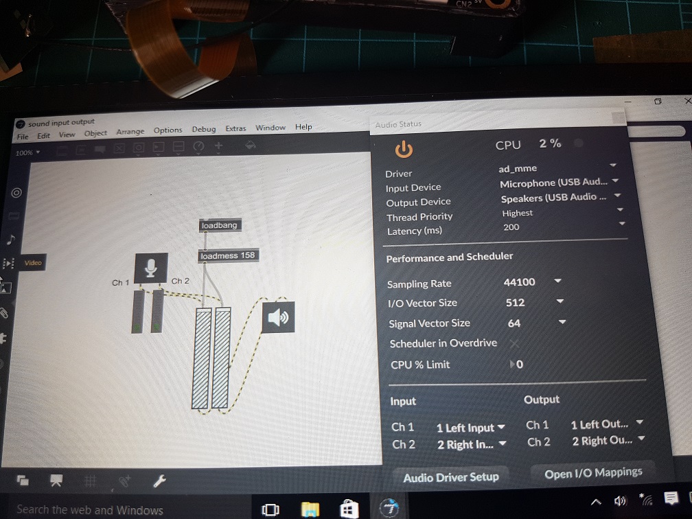
The system which I am using for this project is the Lattepanda, which is a hackable computer and I’ve installed Max MSP into it for this project.
As LattePanda does not come with a sound card for microphone input and the only headphone require input and output jack separately, I had purchased an USB soundcard on carousell and luckily it works.
I was prepared to write the slightly longer code which require to delay the sound from the input to the output, however I found out that there is a “Latency” function in the audio setting and so I used that instead, also, I’ve add an audio gain to the patch to increase the output volume of sound. This is the simplest piece of patch and it works just as I needed so being simple is really good!
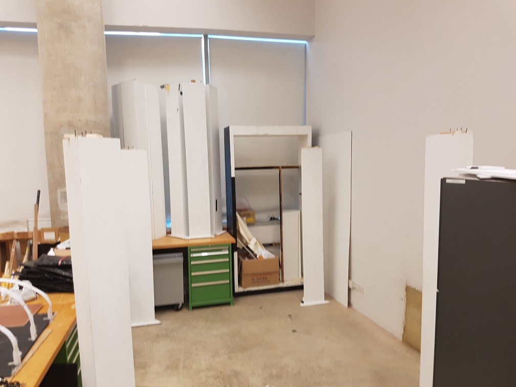
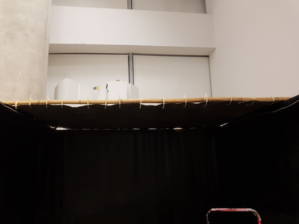
ziptie were used to secure the flap onto the pole.
after ziptieing
Ziptie were used to to make sure it looks nicer and does not collapse, again, structural strength is the main priority as this is made of cardboard and I am lighting fire in it, I don’t want anything to collapse onto the fire.
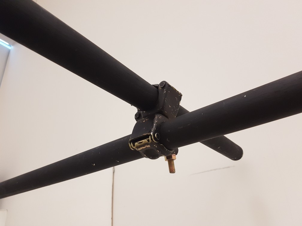
Afterward, I tied the structural loop which my candle stairs will be attached to it later, it was tied to make sure nothing collapse again.
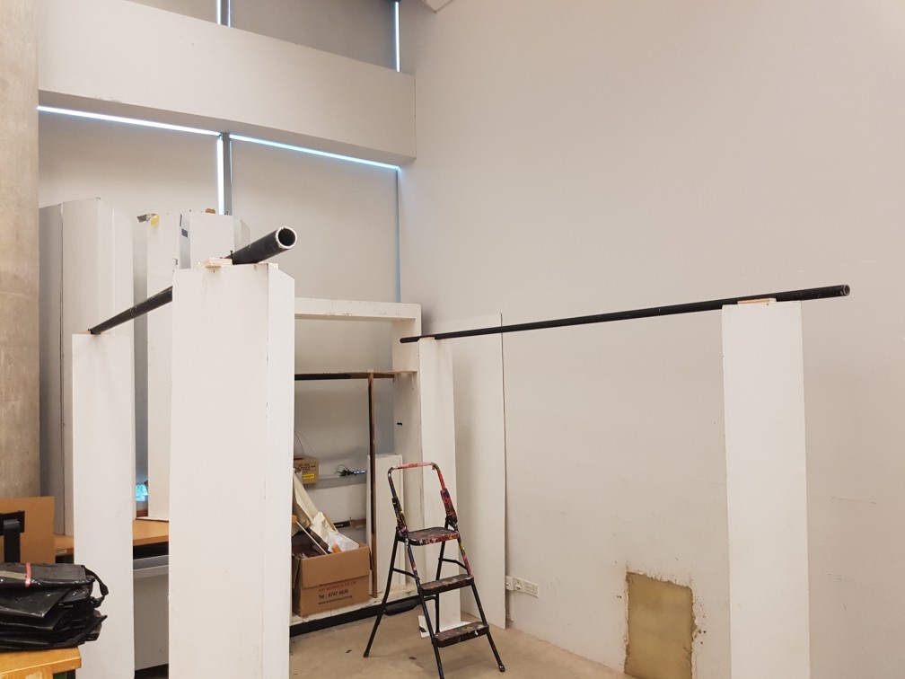
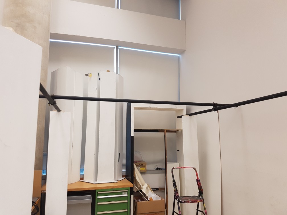
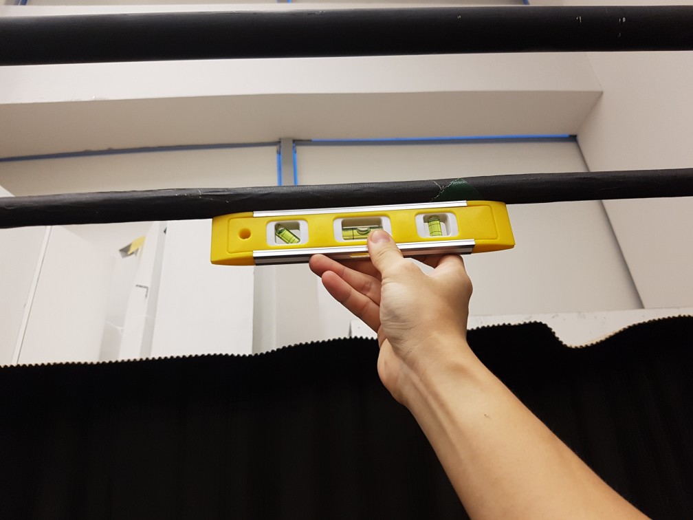
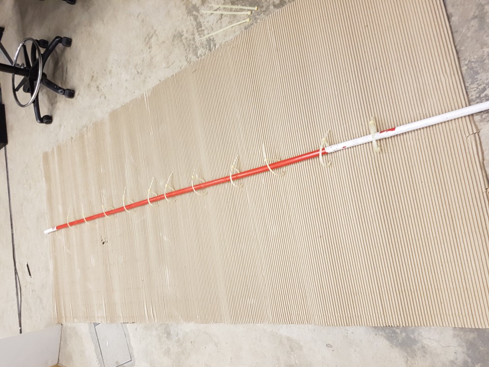
poles were put in place
to see if my loops were leveled.
Next, the sides of the candle stairs were secured with metal plates for hanging.
and its measured to make sure that it balances while carabiner were used in case i have to remove the candle stairs from the structure later. but i think it sure does look good here!
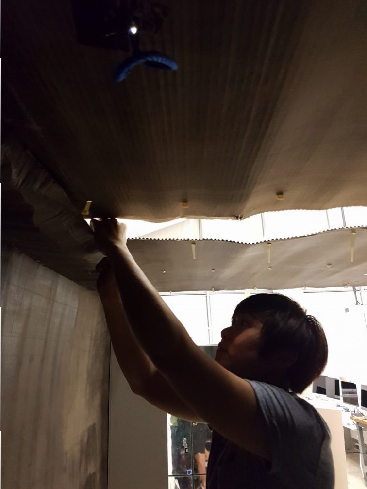
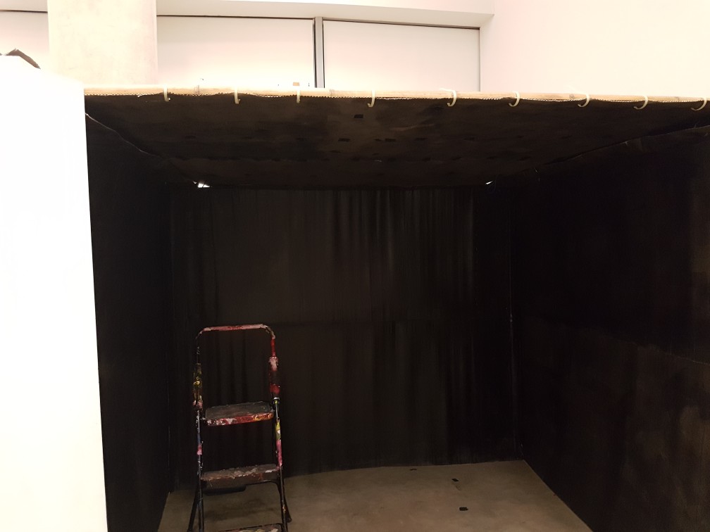
after I confirmed that the structure and overall look of the dark room, I proceed to build the roof of it, which is the most difficult piece to be build as it is really prone to collapsing and I did not want the structure to be seen inside, What i want to achieve was to have all structures outside of the dark room so it will feel legit like a room when you are in it.
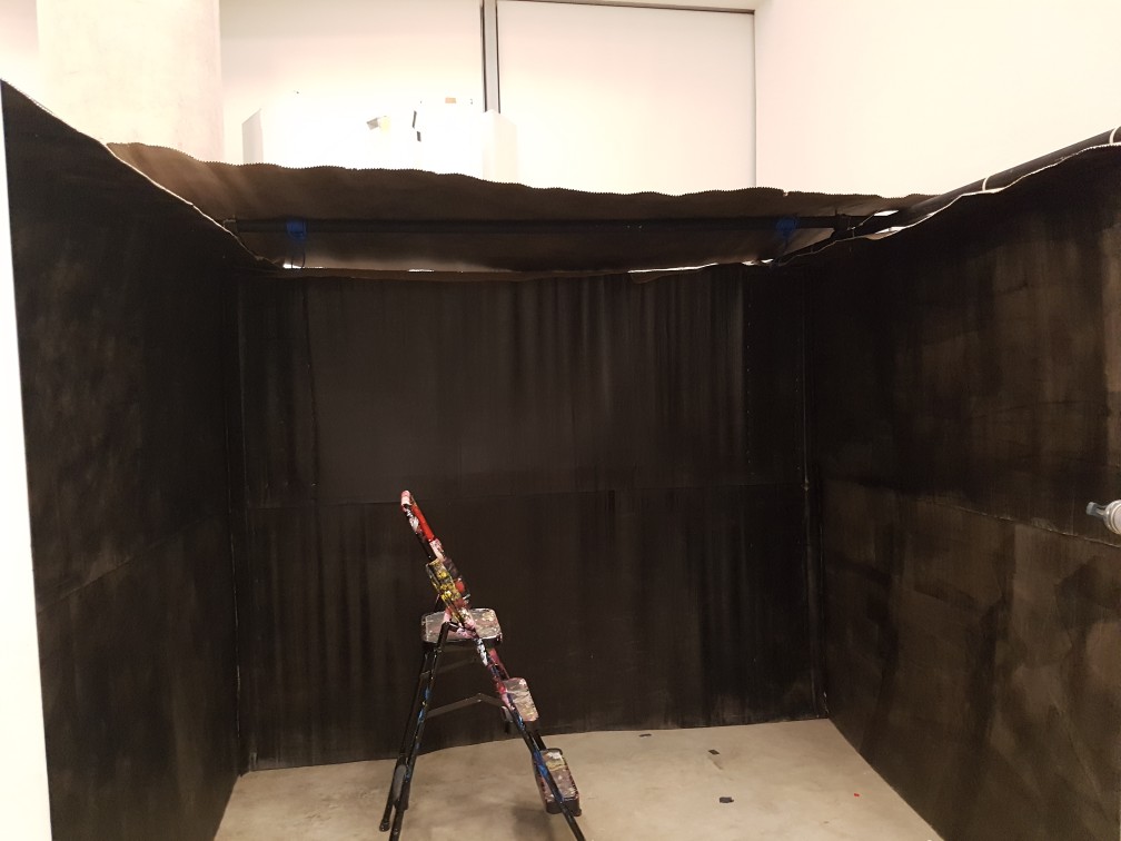
first look of the dark room
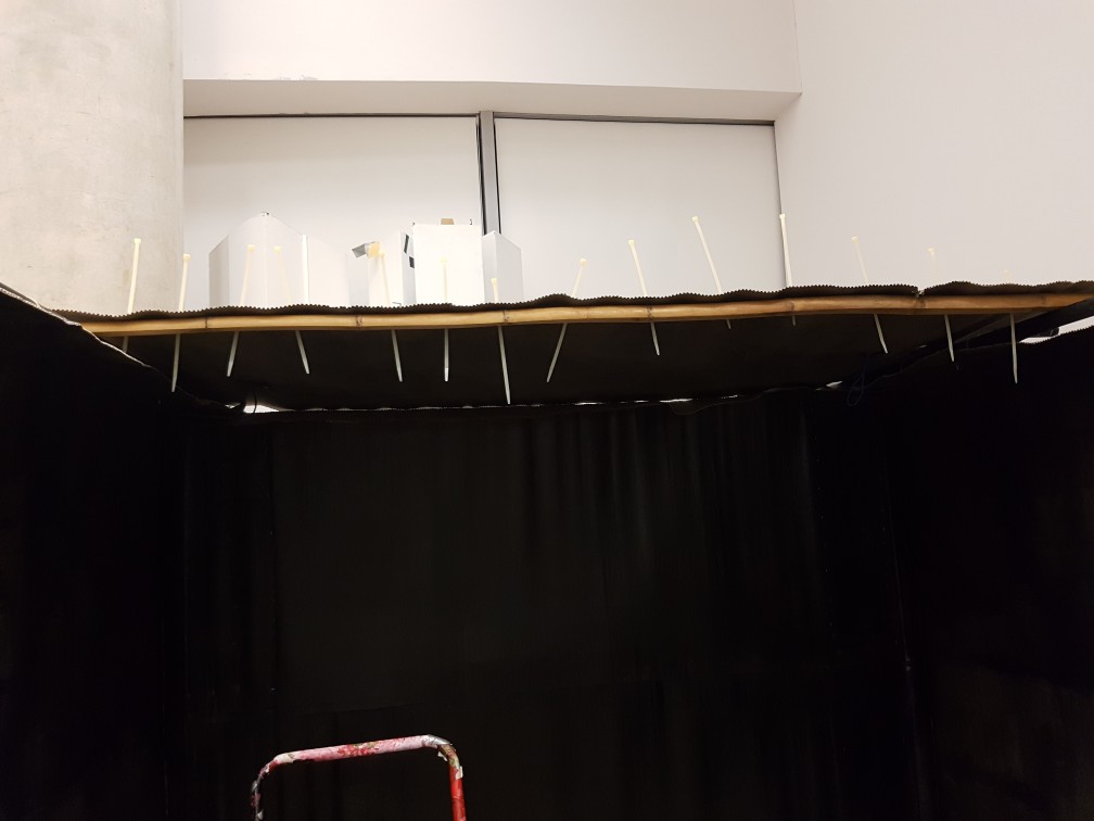
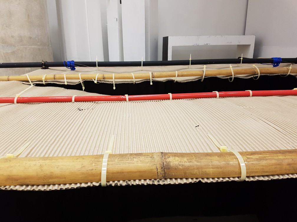
then i tried to secure the bamboo for additional support
but remembered that i want the structures outside so i flipped the pole out
and then again, it is easier to do it on the floor then bring it up.
so I cut and tied the cardboard roof onto the support on the floor and bring it up afterwards.
but I’ve realised that I should not fasten the previous pole as this new piece of roof has to be ziptied onto the previous pole too
so I’ve removed and refasten the ziptie
placing the ziptie through the small hole
and I sprayed it with adhesive just like all other cardboard overlap to increase strength and reduce light leak
the top of the roof with all cardboard fastened with ziptie.
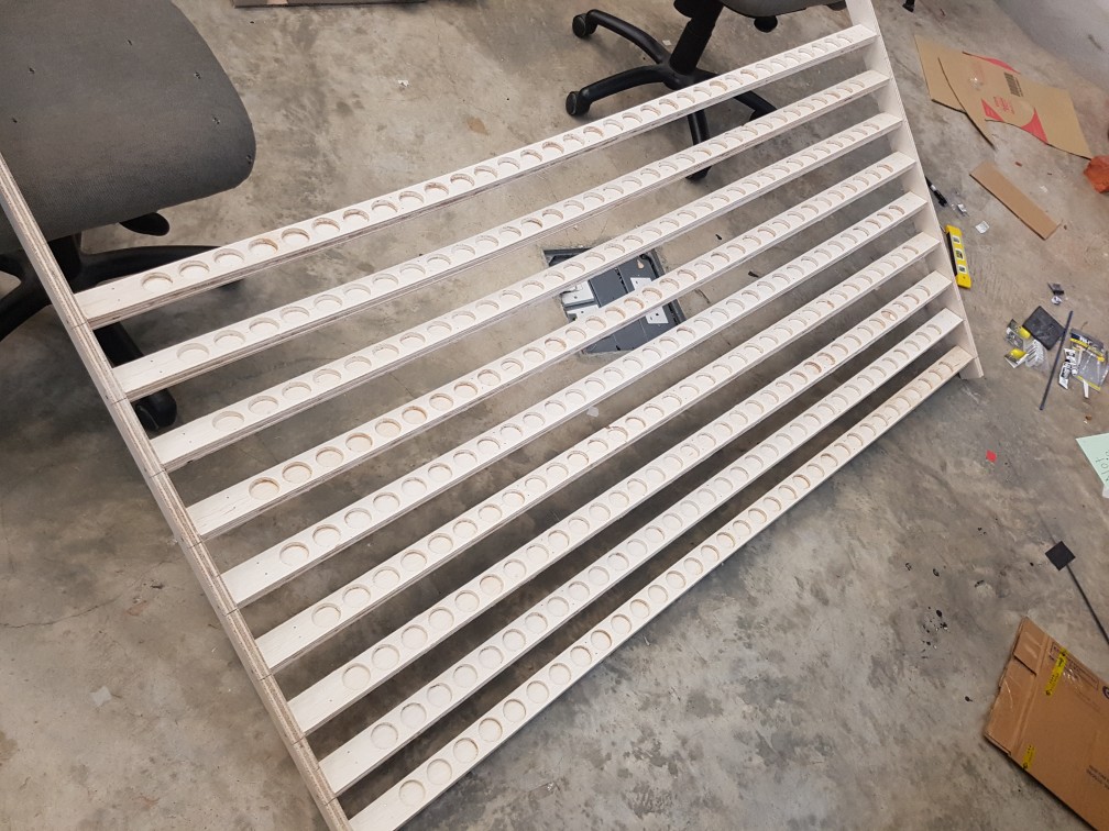
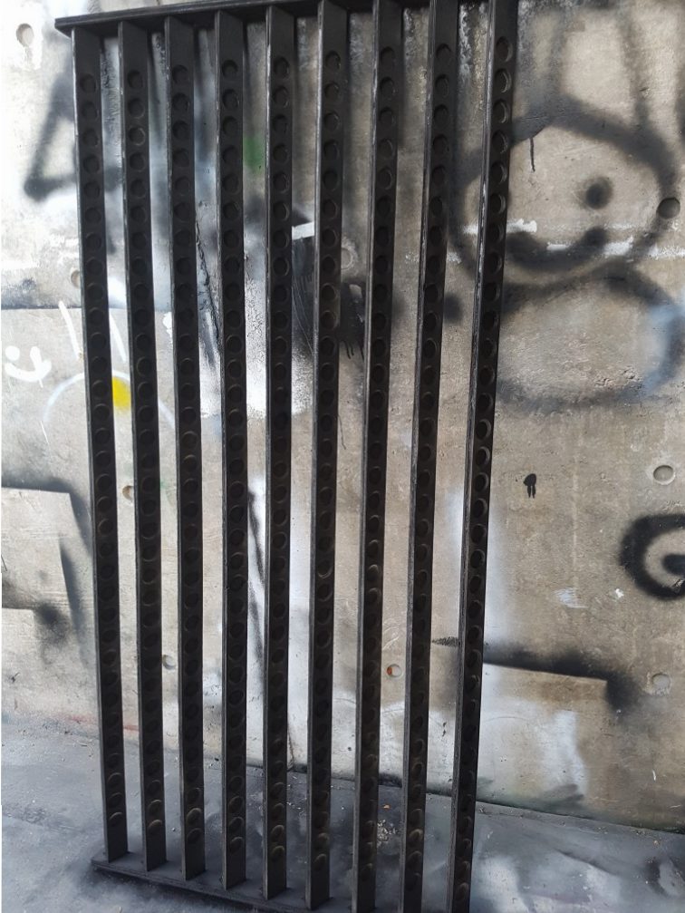
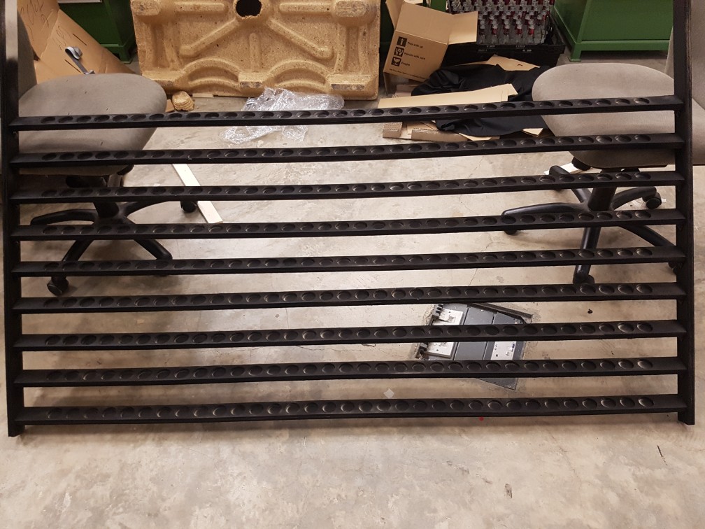
To build the stairs for the candle, I’ve estimated the size of it to be 180cm long and each step should be 5cm wide as the candle is 38mm, so having some tolerance for me to drill holes to place the candle into each hole would be really good to prevent the candle from falling off the stairs. I’ve not decided the total number of steps but since they sell 9mm thick plywood in the size of 2400 by 1200, I could possibly get 22 planks of 1800 by 50mm strip of plywood when I give some cutting tolerance to it.
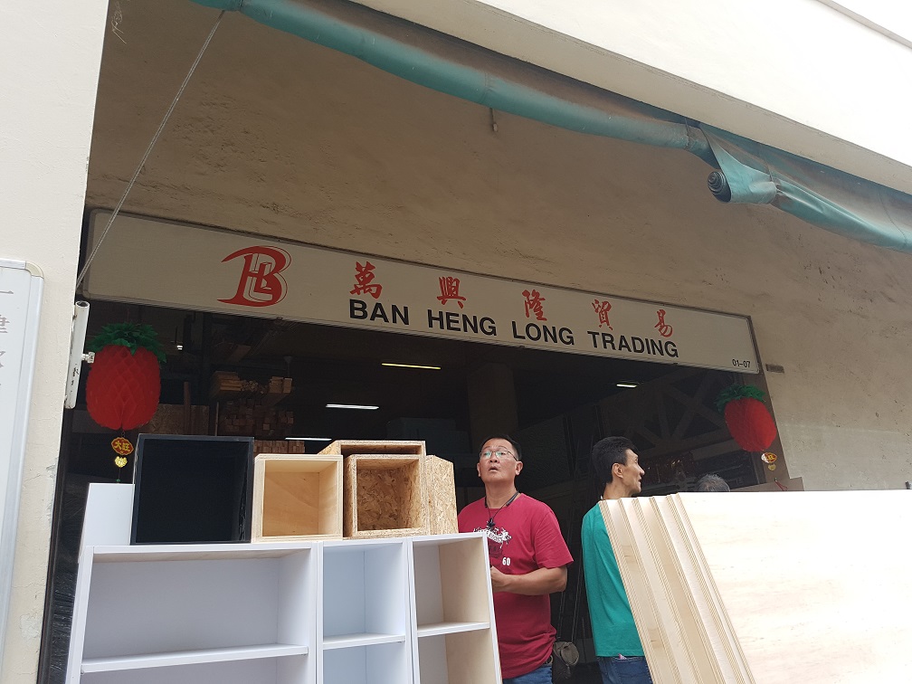
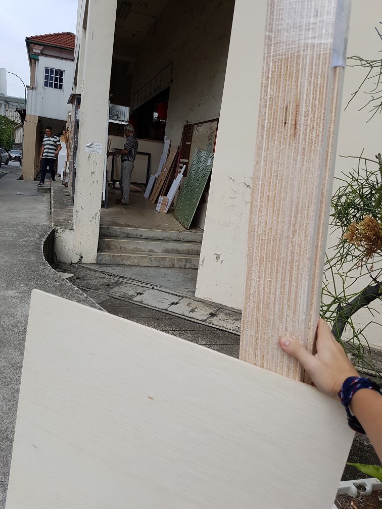
After calculation and calling around to find the cheapest plywood supplier that does cutting service at the cheapest rate, I found Ban Heng Long at Syed Alwi Road which the plywood is $20 and each cut is 50 cents.
Ban Heng Long
i’ve waited for 4 hours to get them to cut the wood as there were many orders before that
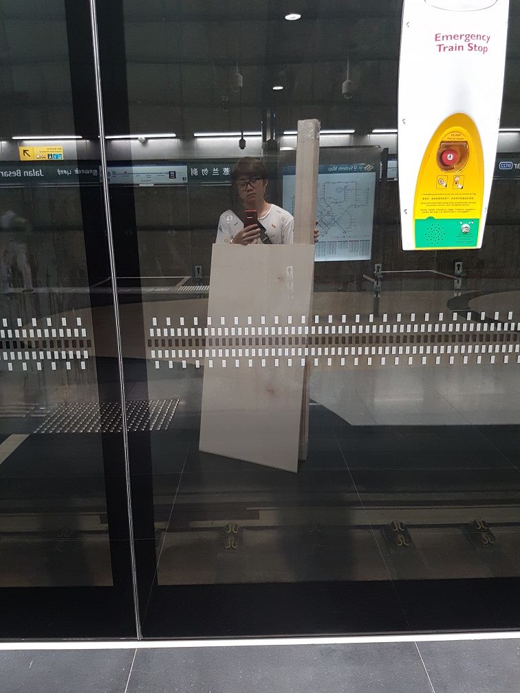
and I just took public transport to school with the super bulky woods
in bus to school
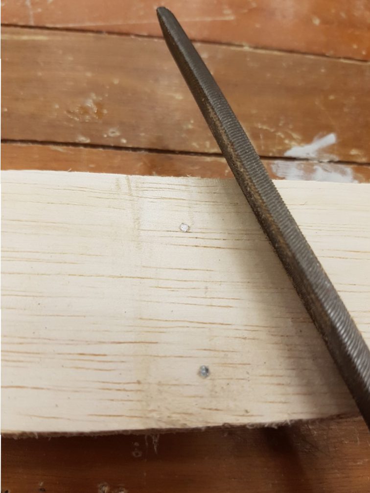
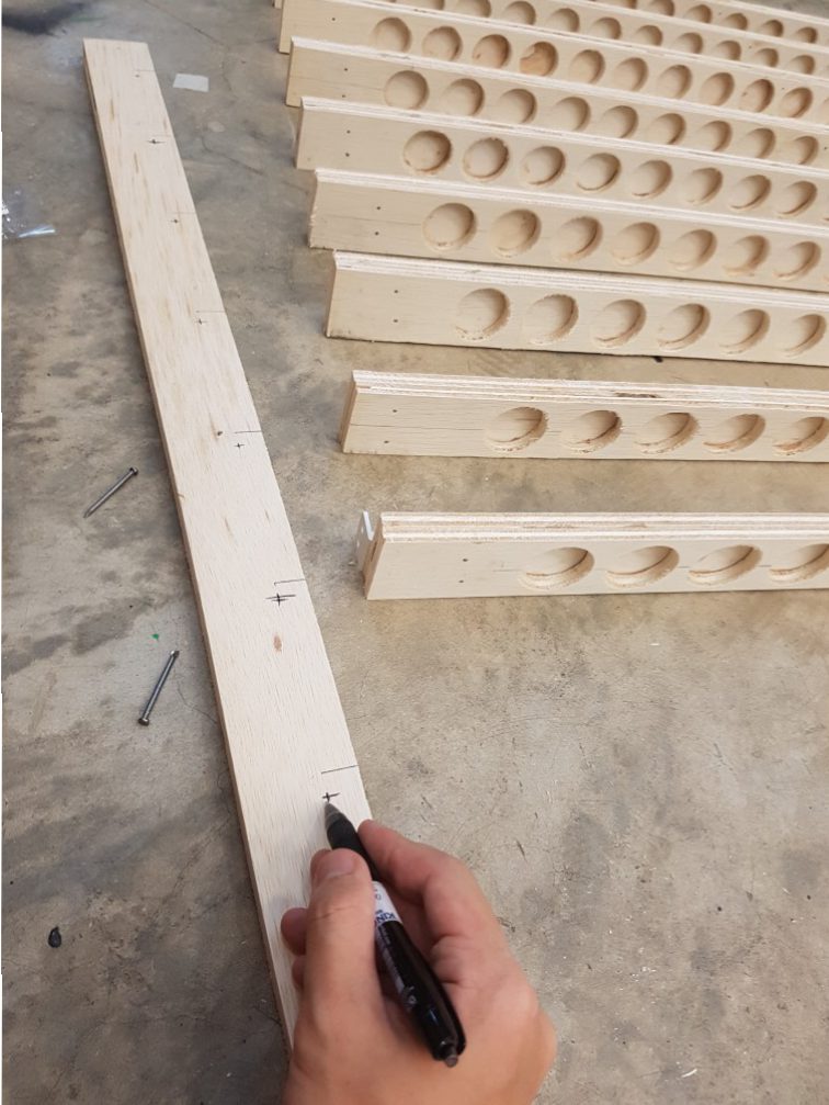
After buying the wood, I measured and marked out the wood for drilling later.
drilling a small hole as the center point for accuracy.
I bought this hole saw at Banheng long and I al really glad that I did, although it was tedious but it could be worst
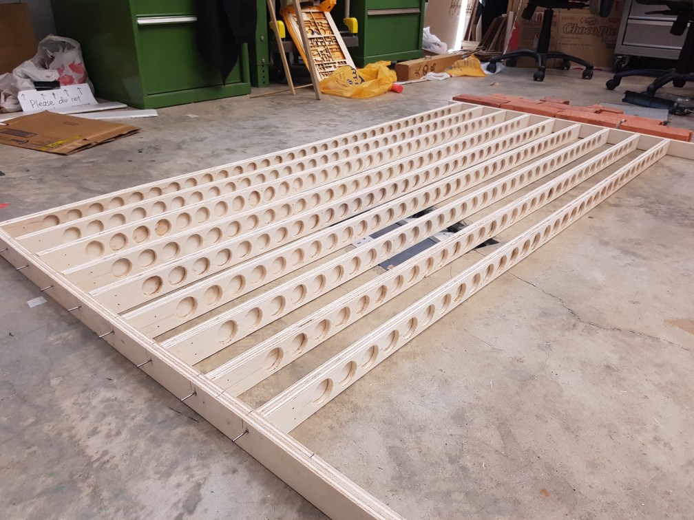
this seemed nice but the height of this might be too tall,
so I’ve reduced the distance bettween planks
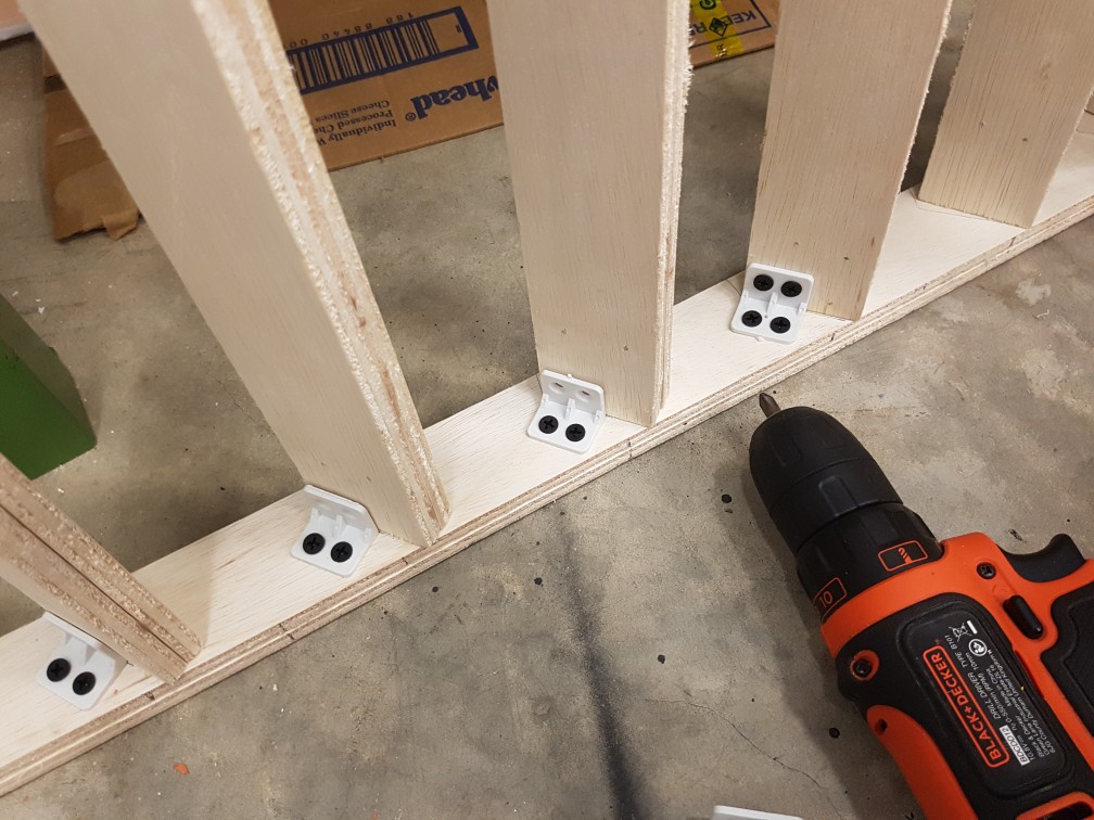
marking of the point to secure initial nails
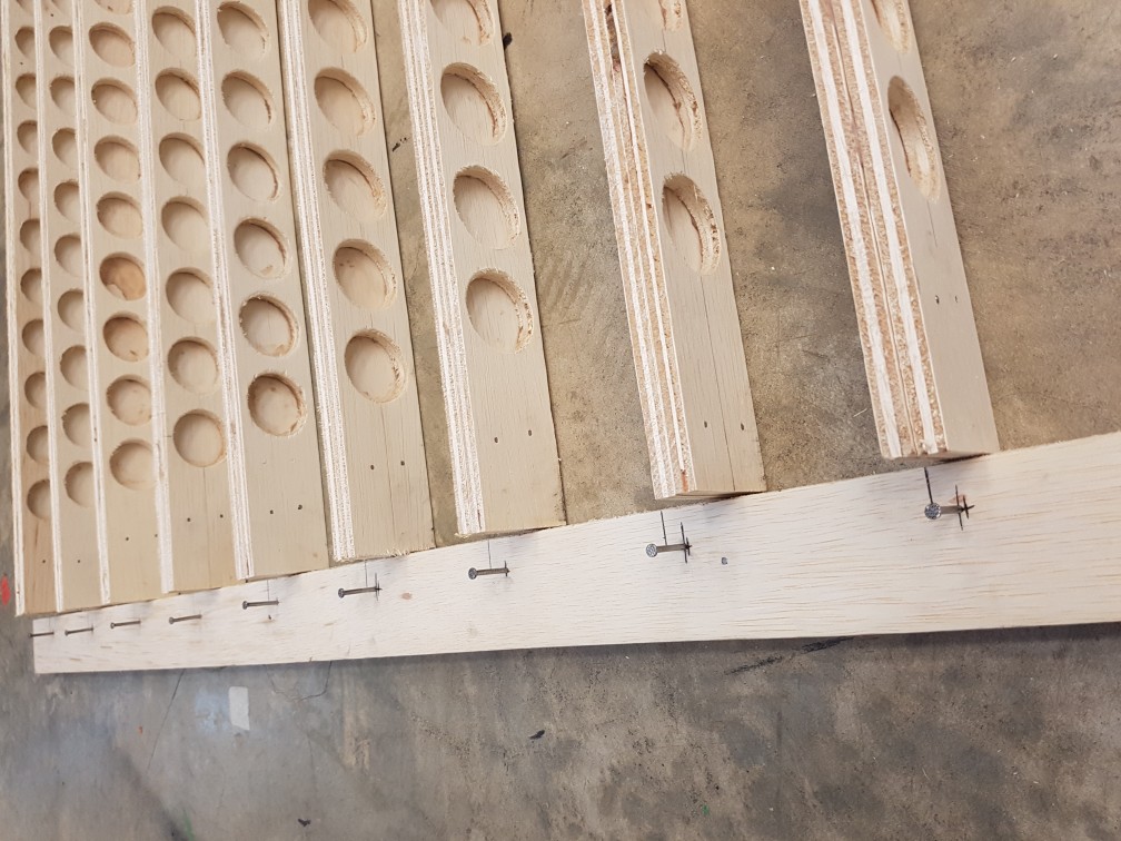
first I drive the nail through the side plank first
then driving the nail through the main plank
this was done by having bricks on the other side to hold it with constant adjustments
after the nails on the side was done…
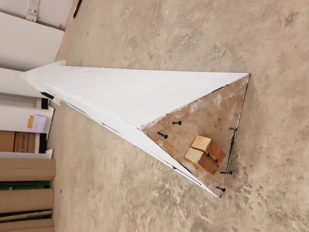
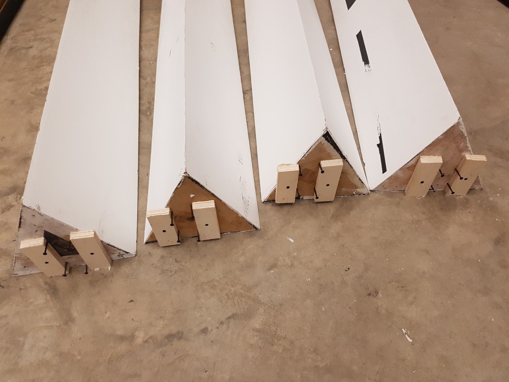
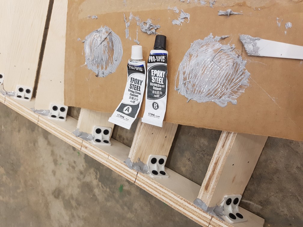
90degree support were then screwed to secure each planks.
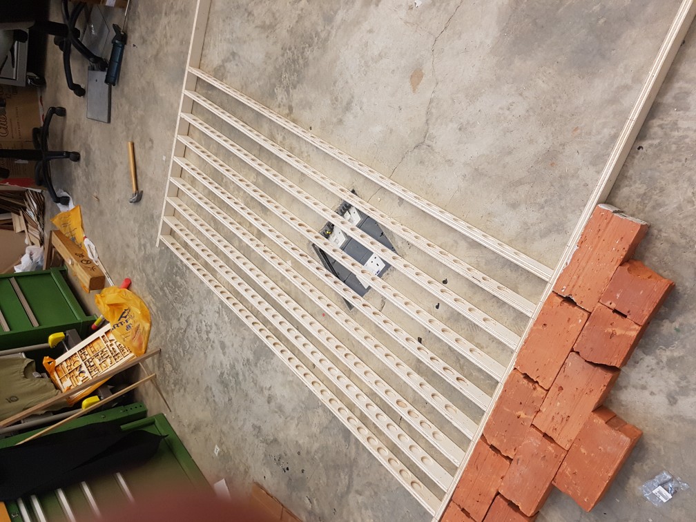
then steel epoxy were added to increase the contact and triple secure each planks.
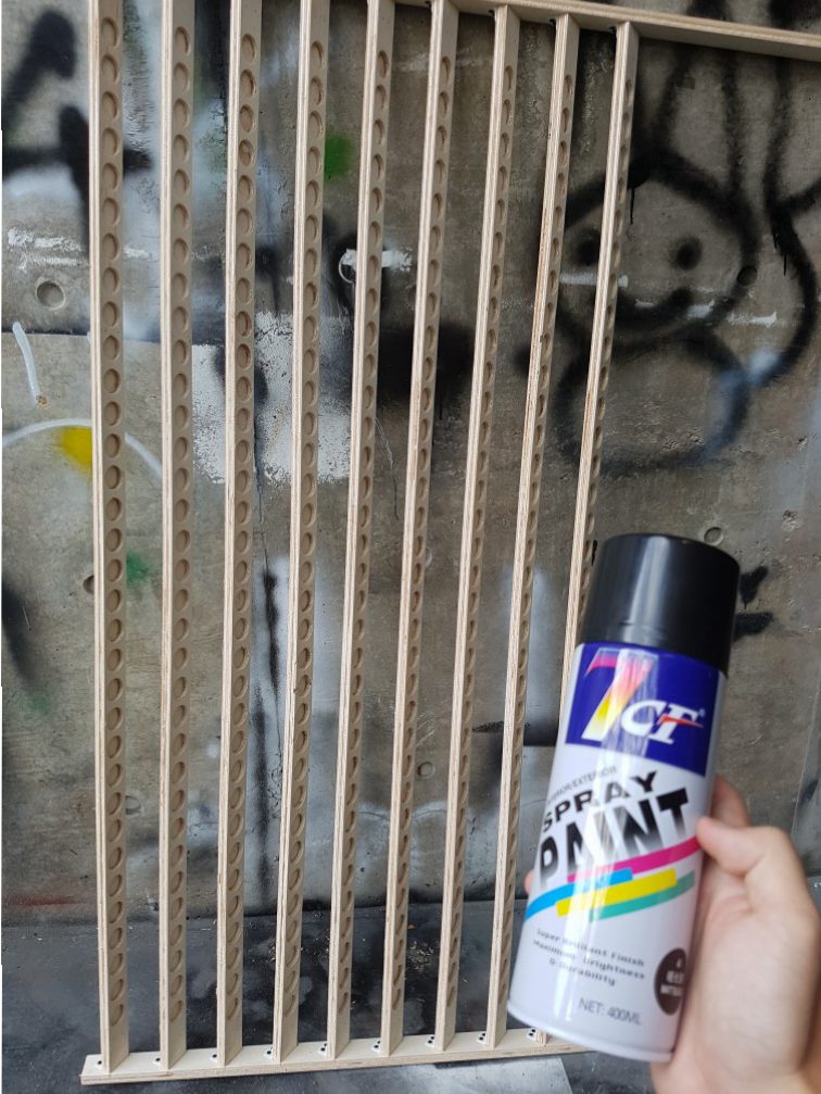
Next I brought it down to spray it black
after spraying
after drying
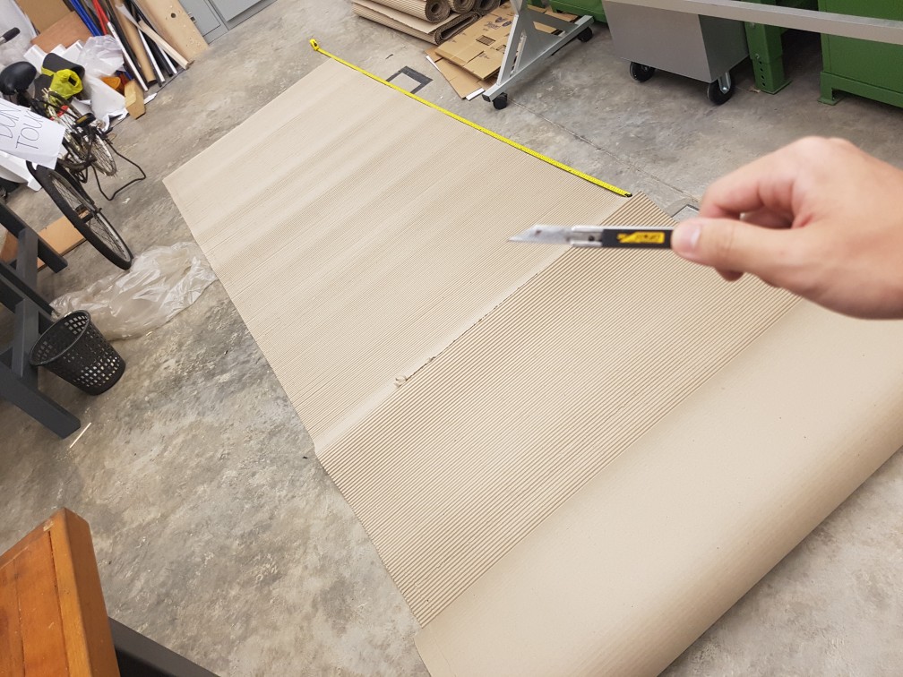
After that, I’ve purchase a 30m cardboard roll to build the dark room for my candles as I would really like to give a feeling of a customized space which one wont feel like in the same space when we are in the one I created, which actually is another space within what we are always used to, the IM room.
I cut the 1.2m by 30m cardboard into 8 pieces of 1.2m by 2.7m piece
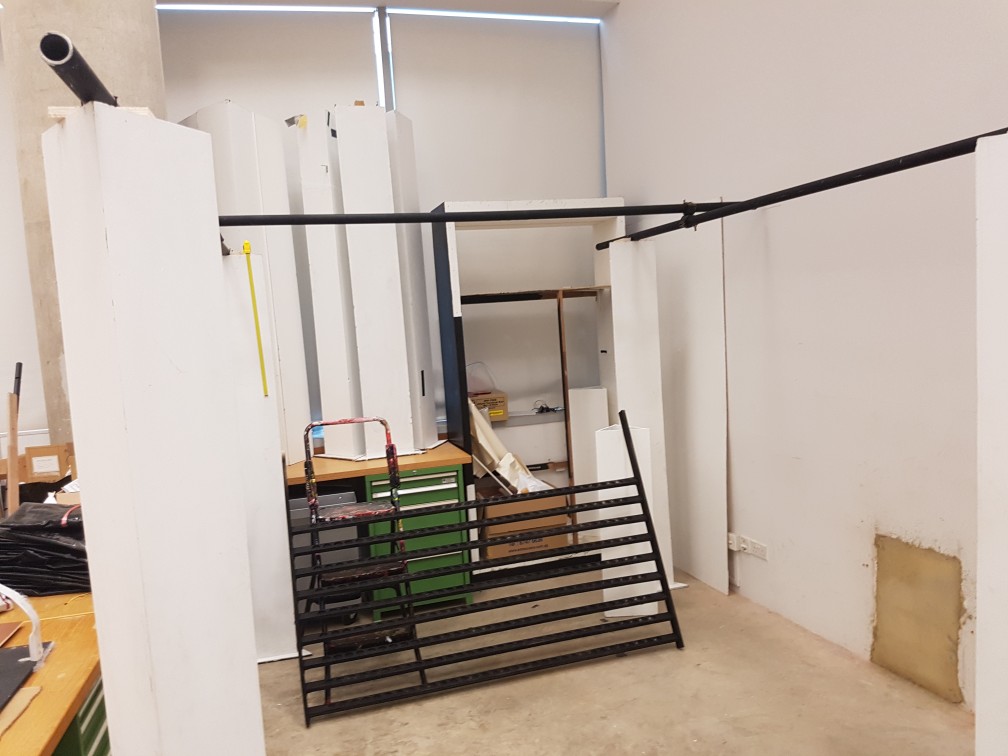
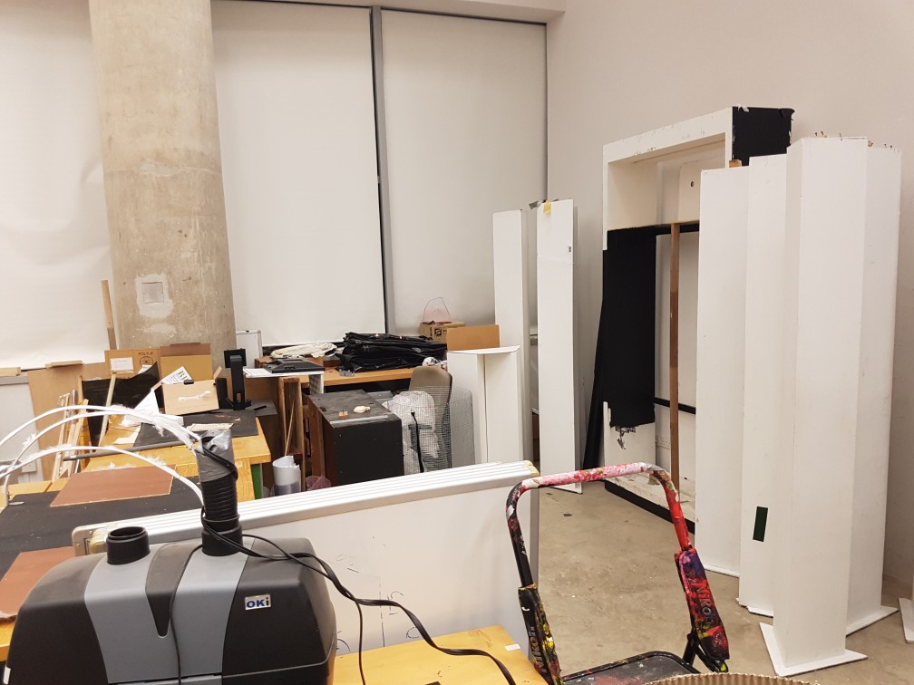
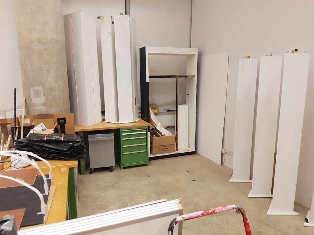
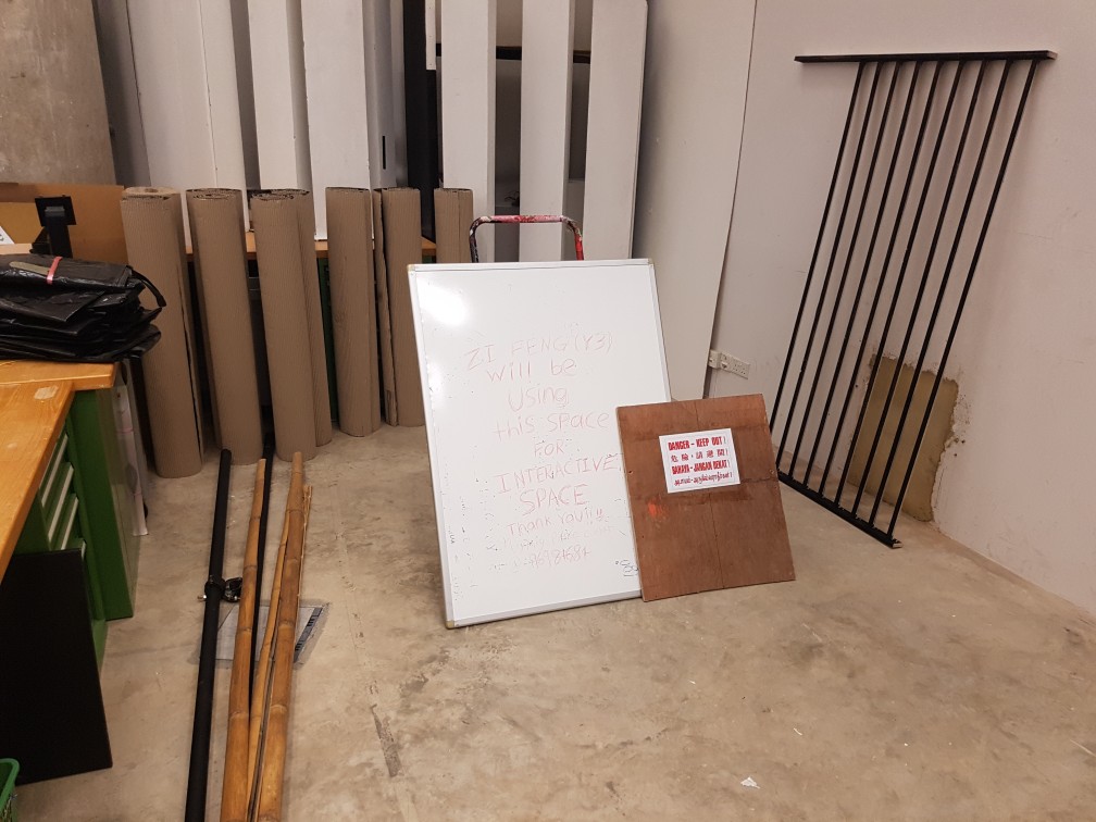
After dying, I brought the cardboard pieces up and decided a place to build my dark room… And I’ve decided to use the space that lesser people used in IM room which is the corner with lockers, however I have do do quite a bit of packing up and shifting of the tables to make space.
after shifting of tables but before packing
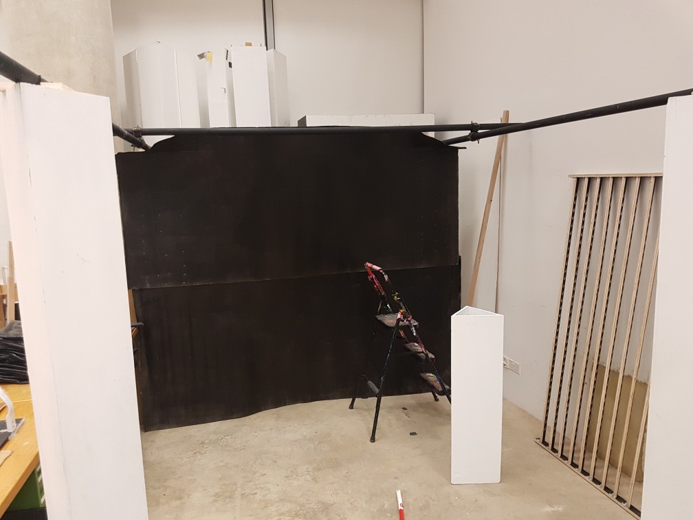
after packing and arranging the space into a 2.7m by 2.7m space.
this is the completion of the dark room and to add ventilation to it as i assume it will be really hot and there might be fire hazard if the hot air or smoke is not being ventilated out of IM room.
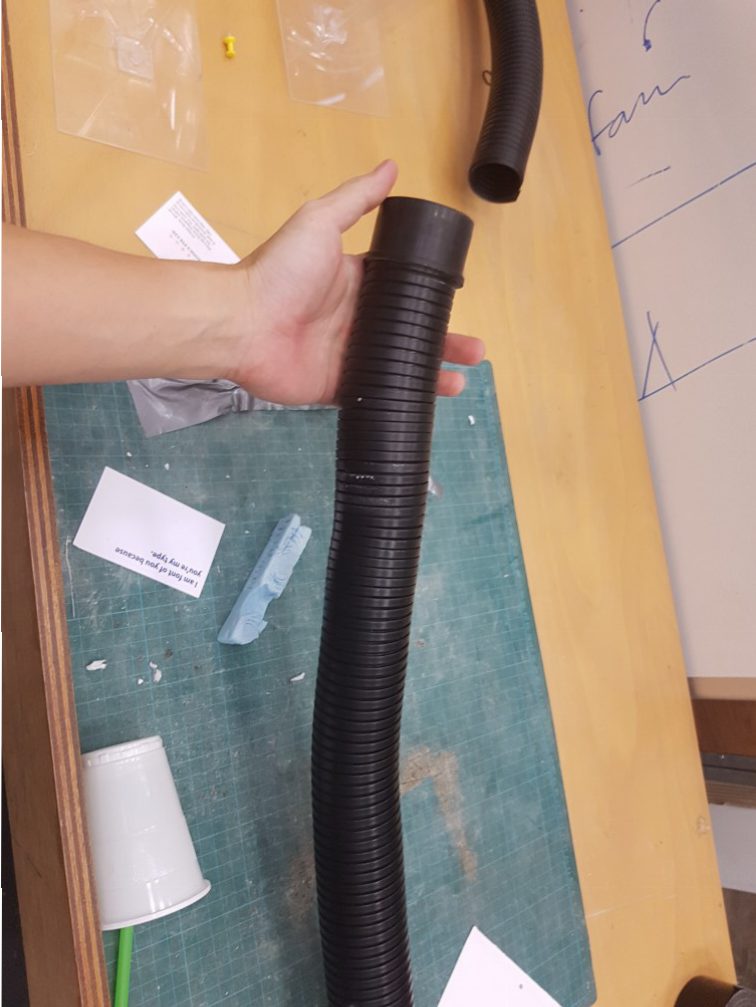
the pipe for the air pump for soldering in im room was damaged so i’ve repaired it
repair completed
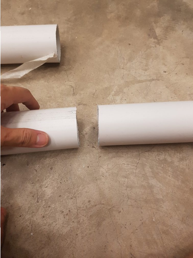
I’ve purchased 4.2m of PVC pipe and ask the seller to cut it into 1m length for easier transportation
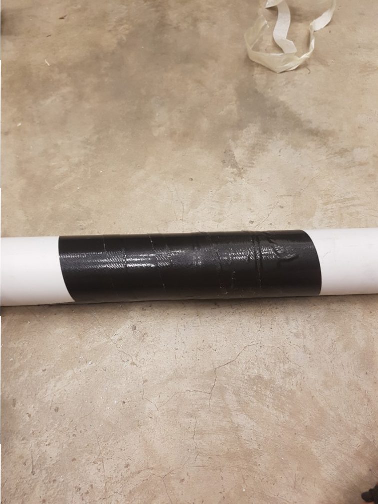
but I realised that i need the full 4.2m in the end so I stick them back
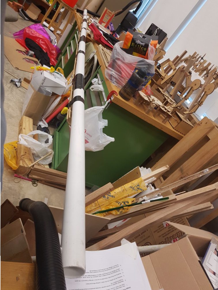
I also fasten the 4.3m PVC pipe to a bamboo pole to increase the strength. the machine was placed at the only openable window to draw the smoke out
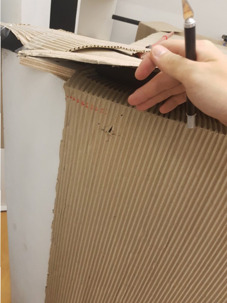
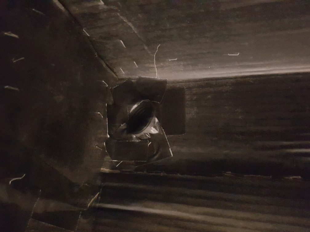
did a marking from the inside of the dark room for the ventilation pipe
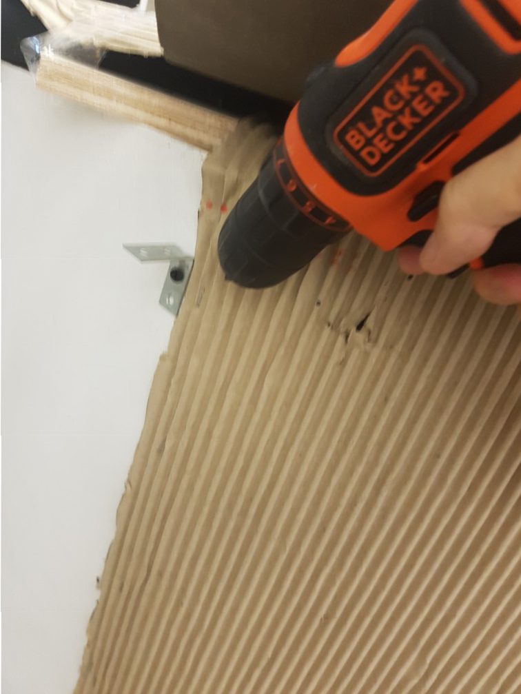
I screwed the 90 degree bracket to secure the pipe
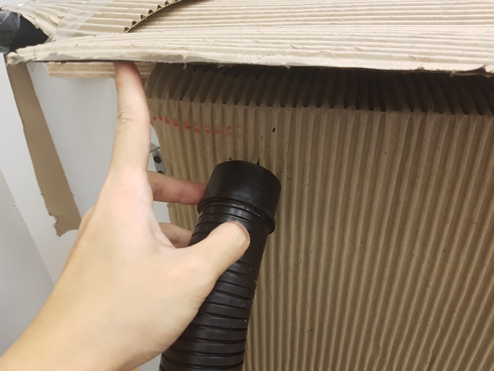
forcing the pipe in
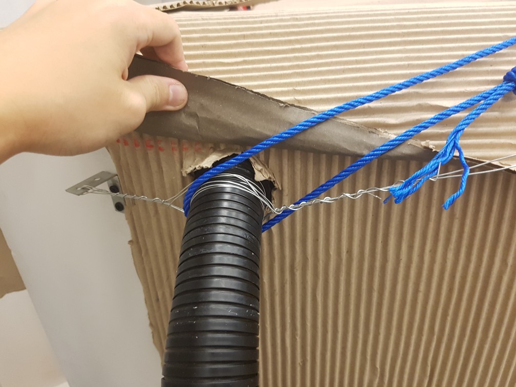
and secured using wires and ropes
tapped from the outside as well as inside.
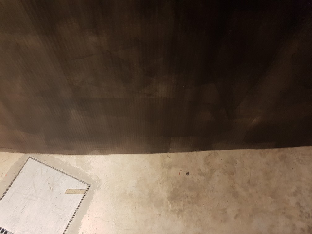
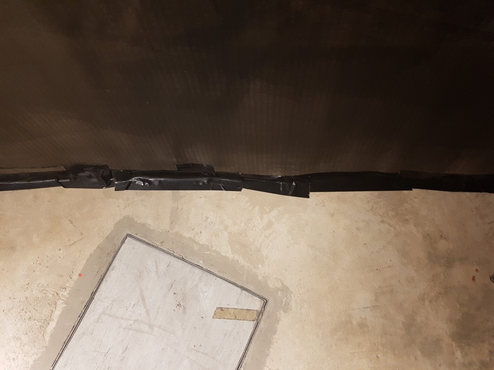
the bottom of the walls
tapped it securely to increase structural strength and remove light leaks
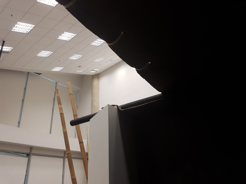
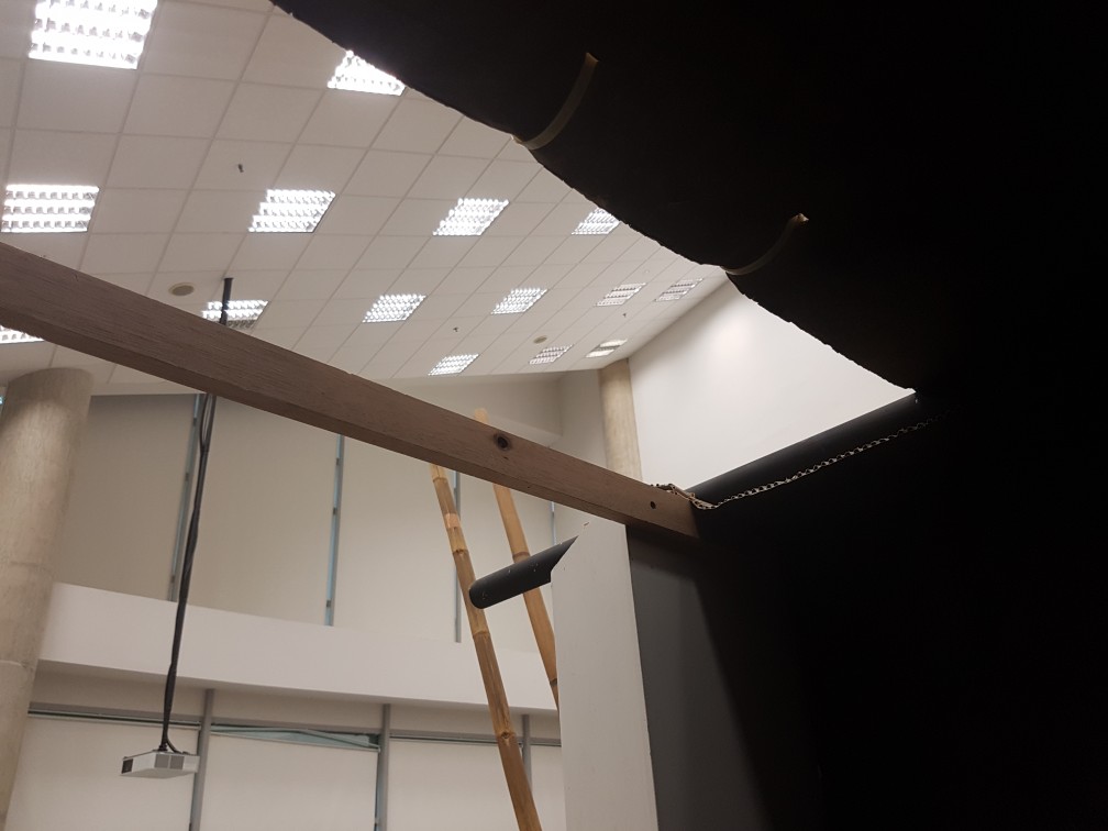
the top of the opening of the dark room
fasten a wooden plank for structural support as well as to finish the roof.
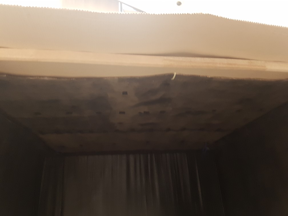
final piece of roof
previous ziptie were removed and re-fastened for the final roof piece
roof folded down
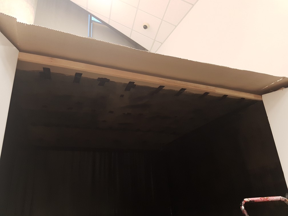
cardboards were cutted for a smaller opening
the side of the opening
the overall darkroom done.
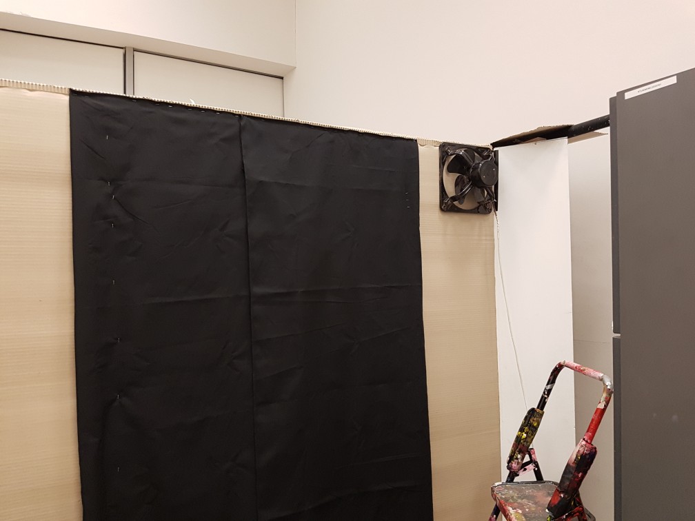
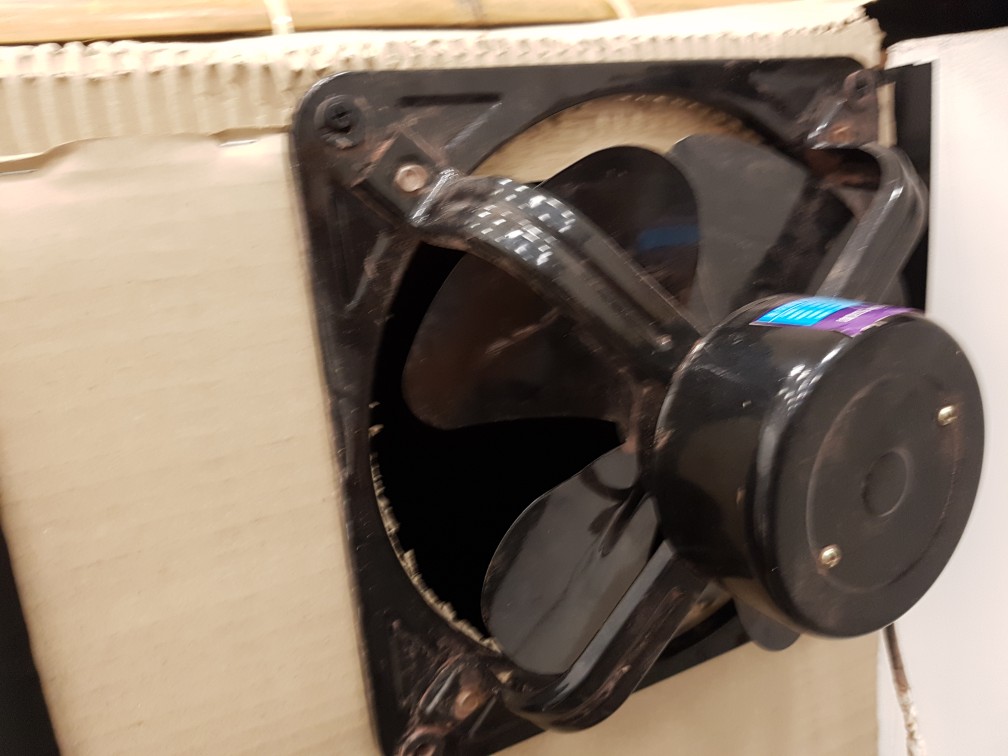
lastly, i realised that the air flow wasn’t that good so i detached a ventilation fan from my house and attached it onto the dark room.
The ventilation fan from my house
attached onto the structure of the darkroom with screws.
and the cardboard was cutted out
cardboard were added to reduce lightleaks.
And the dark room was done!!!
next post will be the final post for the Analog submission for this project.


 To experiment with speed and delay of Lattepanda with unity to control arduino, which is not bad!
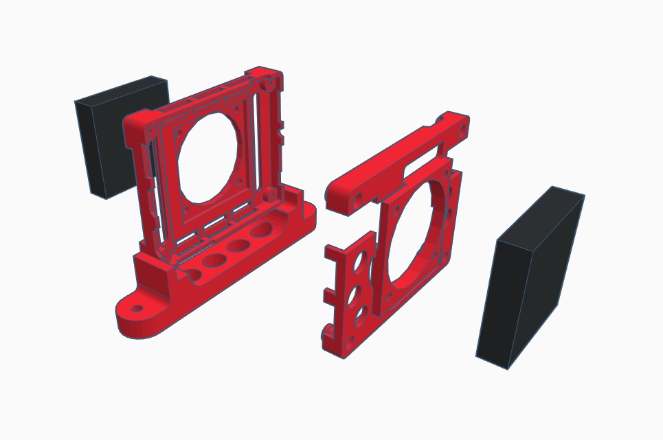


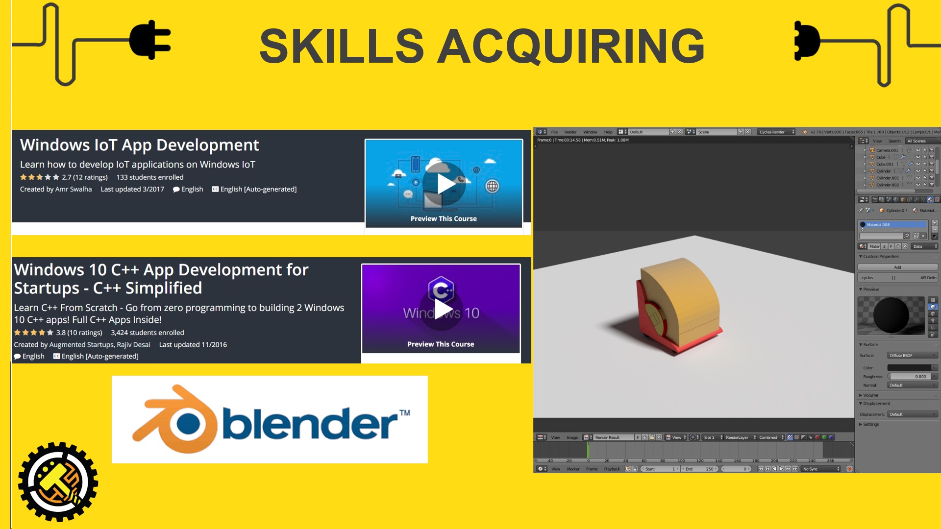


 https://www.udemy.com/the-complete-windows-10-c-course-and-build-2-apps/
 https://www.udemy.com/windows-iot/
 https://www.udemy.com/the-complete-design-course/
 As LattePanda does not come with a sound card for microphone input and the only headphone require input and output jack separately, I had purchased an USB soundcard on carousell and luckily it works.

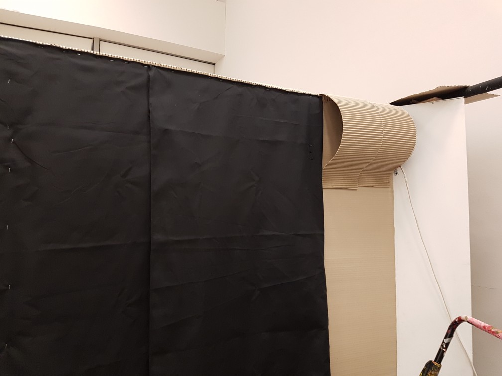
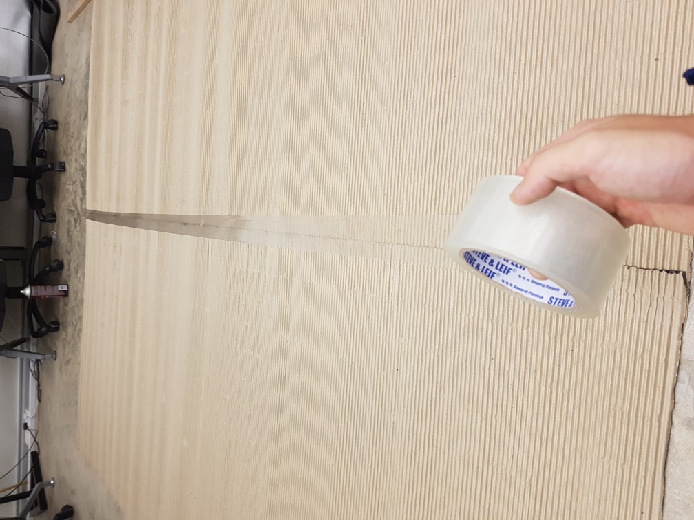 Ive spray mount and tape it at the back on the floor before mounting the side wall as it is SOOOO much easier and nicer to do so!

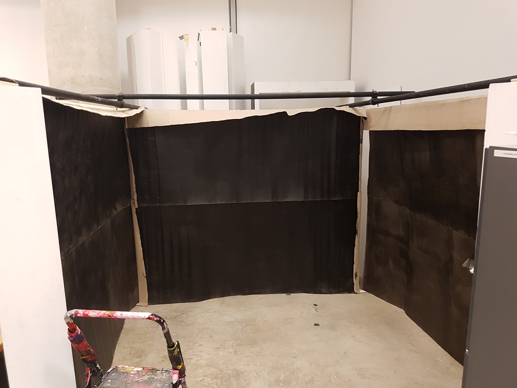


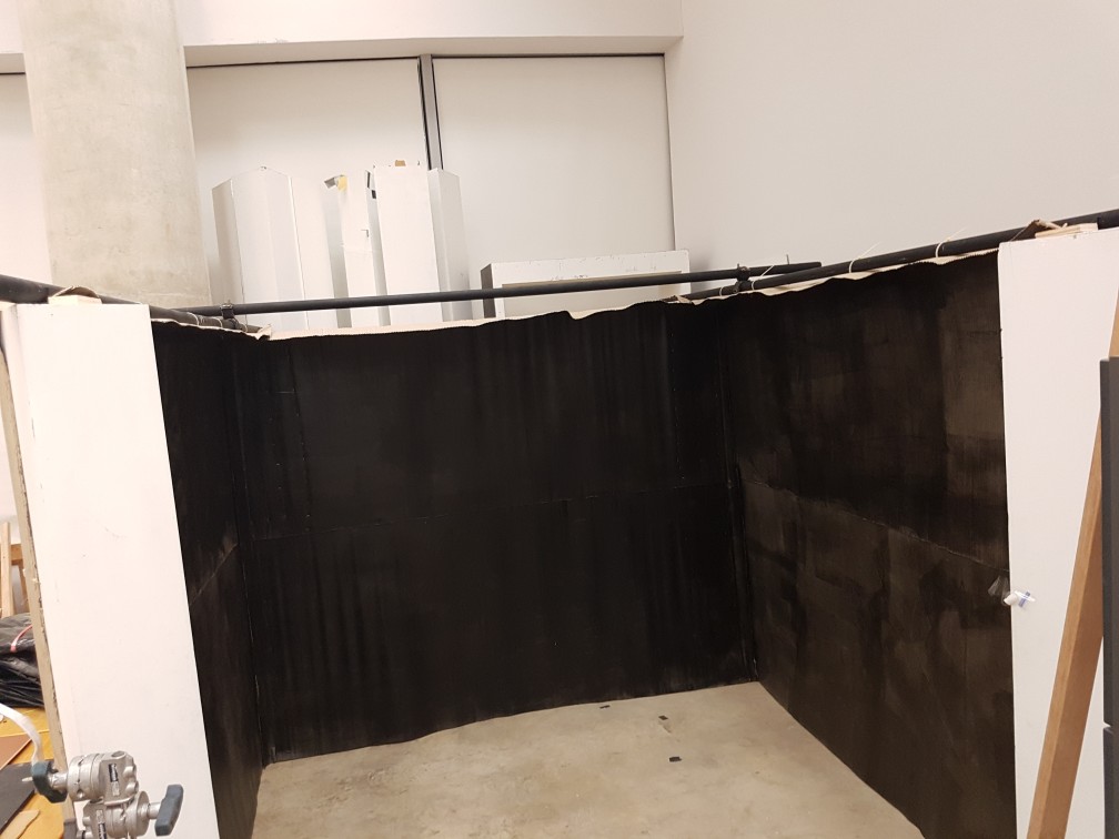


 I really like the overall appearance of it for now!

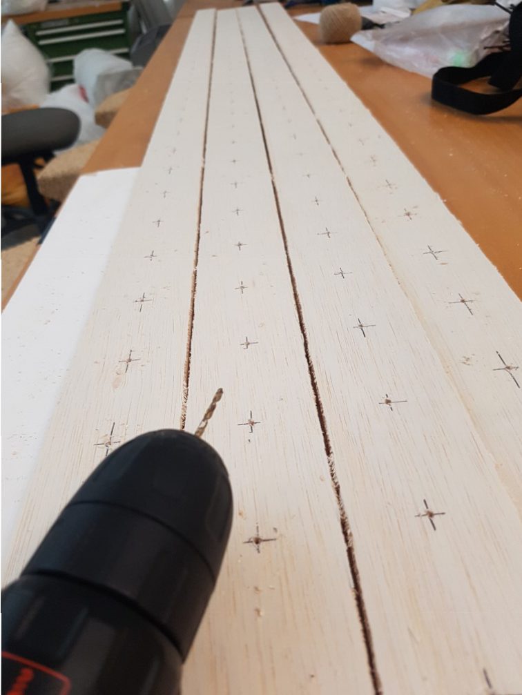
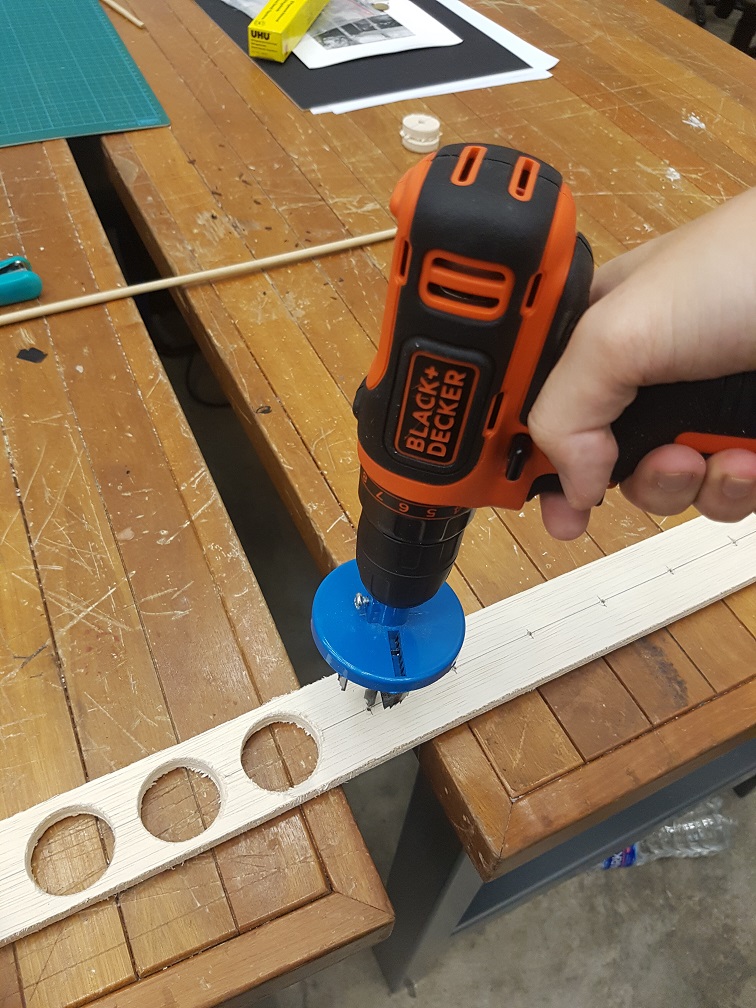
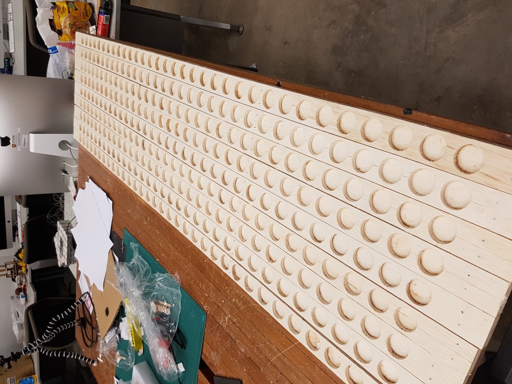
 100X speed and a total of 297 holes were drilled.
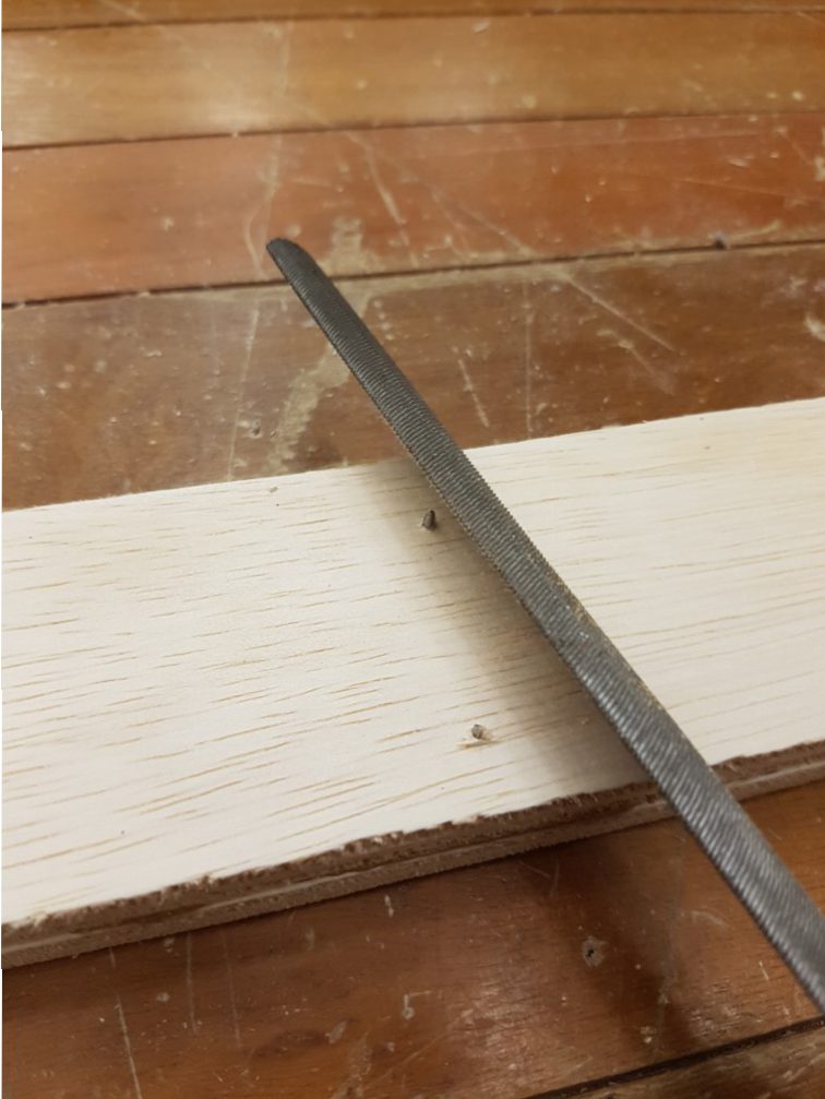
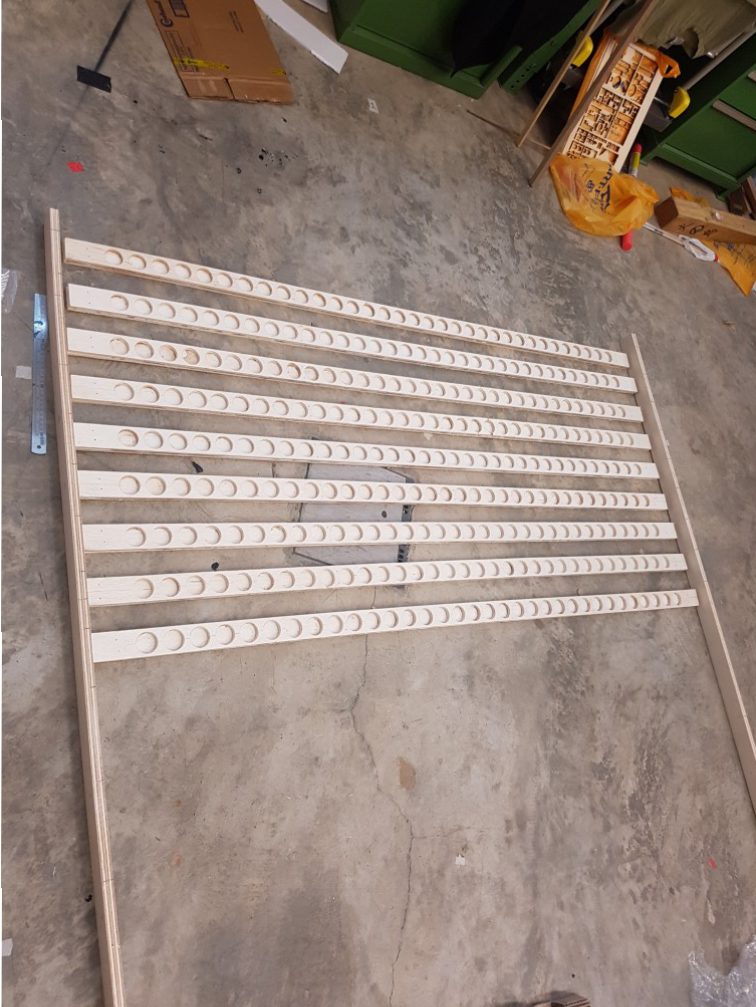
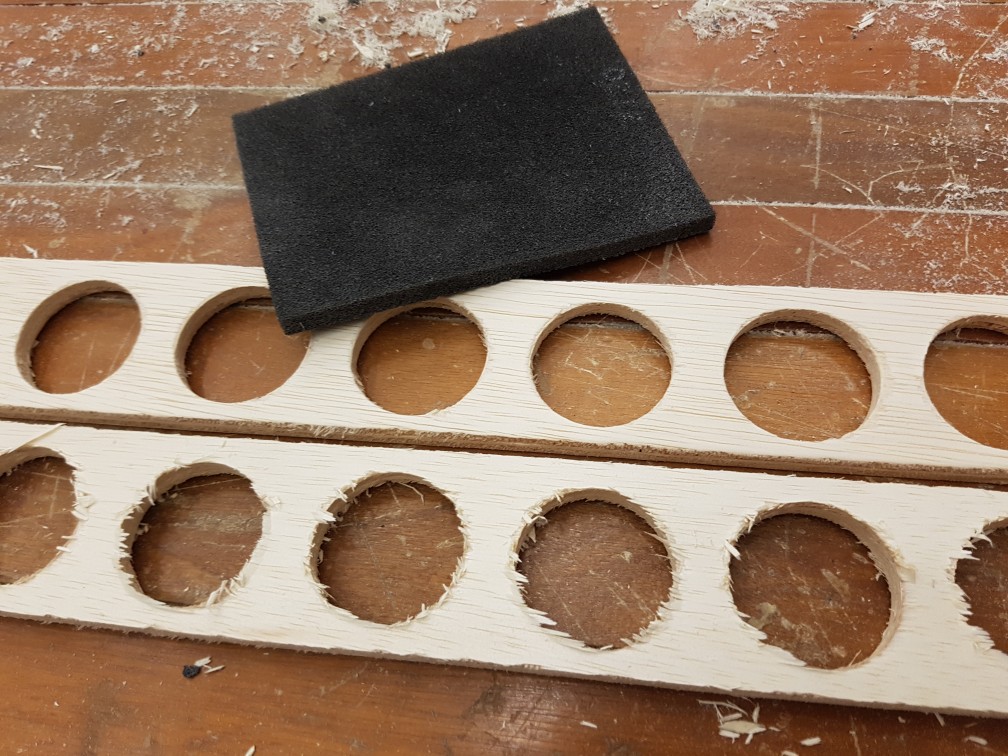 Sanding is so important for the finishing quality
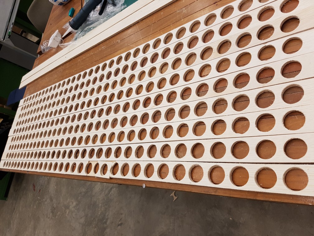 after sanding the 9 planks of 297 holes in total.
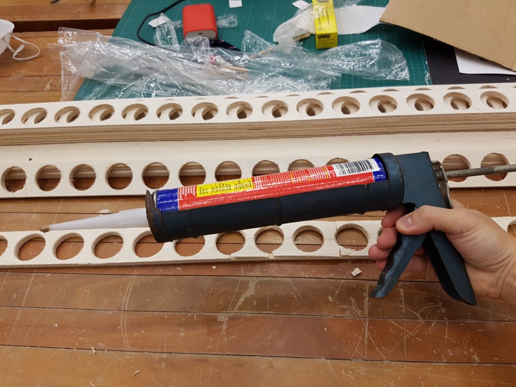
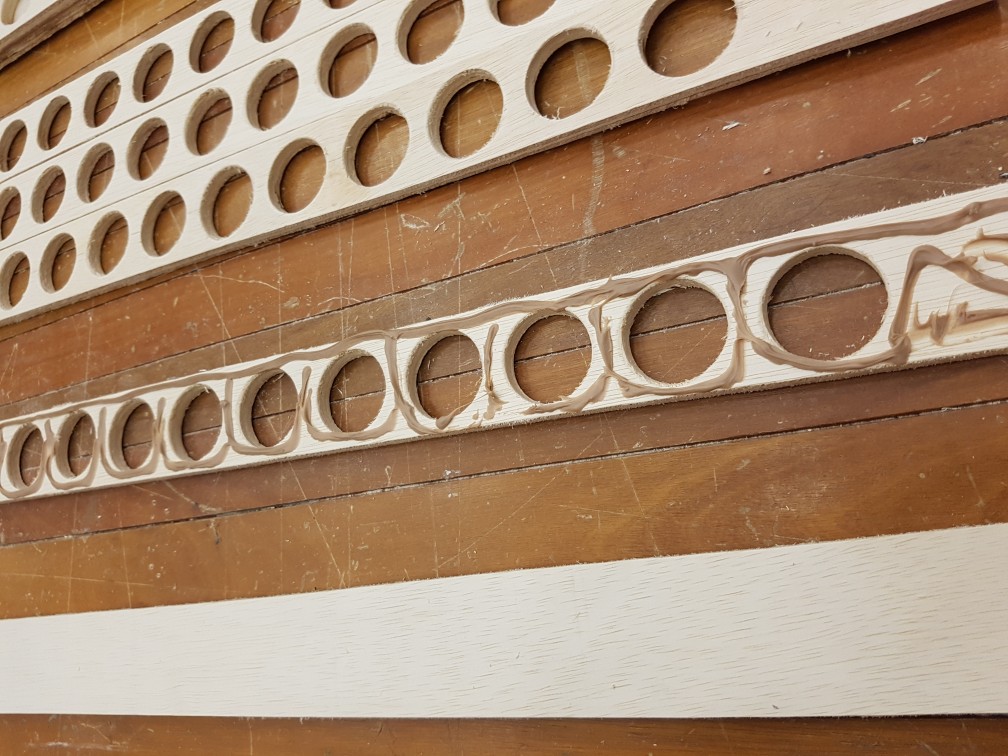
 after gluing done and excess glue cleaned up.
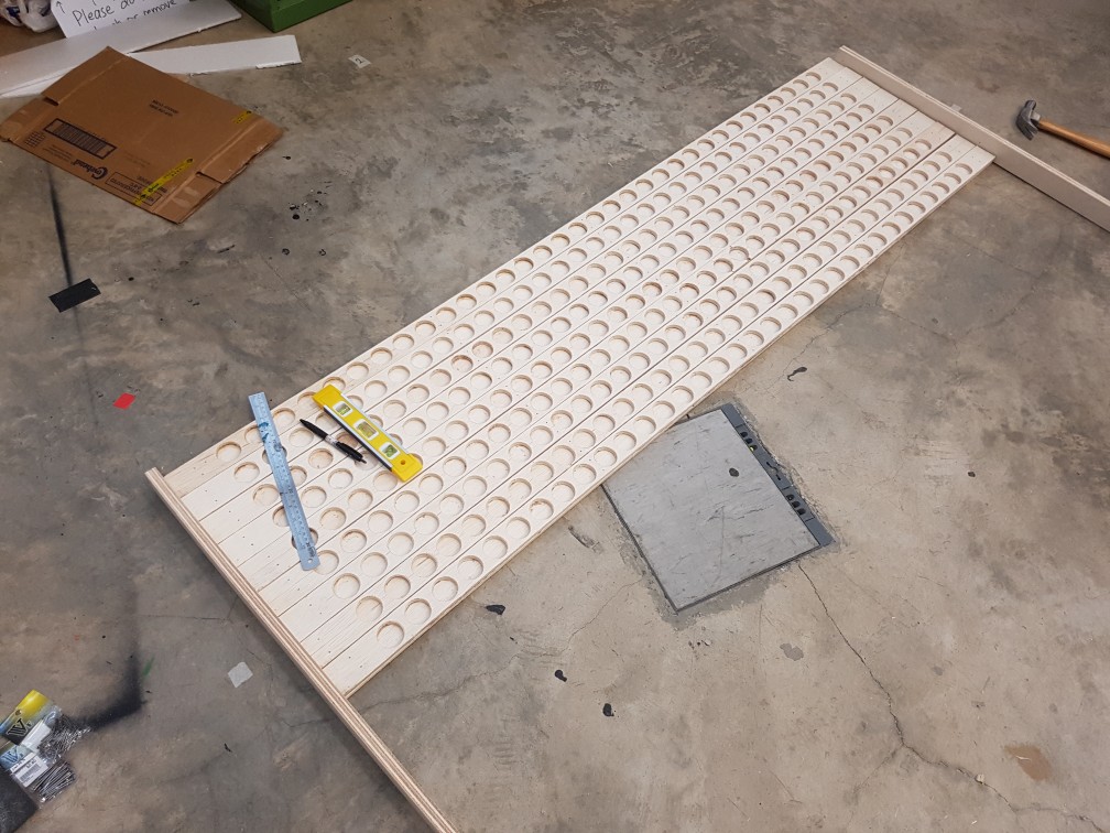


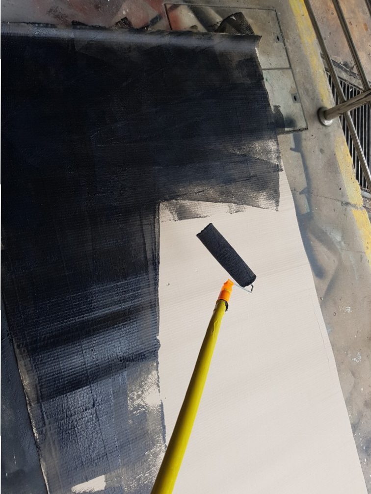
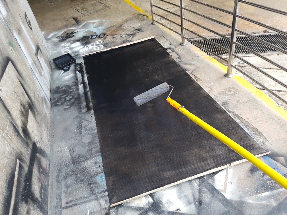
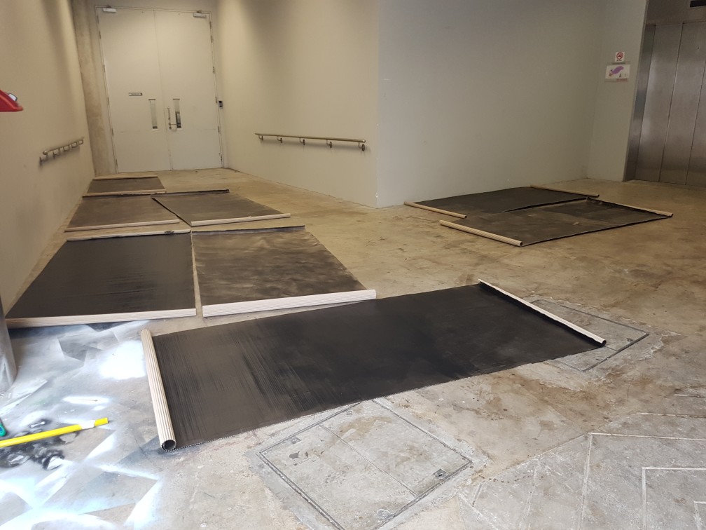
 Painting the 8 piece of cardboard roll with waterbased wall paint at 300X speed. the paint is rather expensive so only 2 piece were fully painted in black while the 6 rest were only somewhat black.
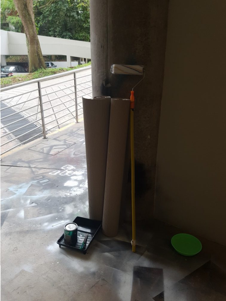


