

Project done by: Emma, Wei Lin, Natalie, Wan Hui
Our semester project is called Light Distance Away. It aims to send comfort by the hint of another person’s presence despite them being absent through the use of our setup and device. A camera will track User 1’s movements when they are within the display area and a white line will be projected into User 2’s room based on User 1’s movements. User 2 will then be able to see the personless footwear moving based on the projected line in realtime, ironically creating a rather haunting feeling of an absent presence, while comforting the user with the reminder of this presence. The physical distance between is shortened to a lighted path as both distant bodies now move together in their respective rooms.
We started with 2 separate development paths after researching in depth of possible tracking methods:
-
- Camera to track object
- Motor to follow path
Our goals for low-fidelity stage:
-
- Research
- How to track person’s movement
- Indoor Positioning System
- Image tracking
- Bluetooth
- Heatmap
- Color
- Computer Learning
- Gyro and acceleration
- Ultrasonic sensors
- Indoor Positioning System
- Possible softwares to use
- Processing + Open CV
- Arduino + Pixycam
- What kind of hardware to control motor
- DC Motors + Motor Driver Shields
- Consider dry hacking remote control cars
- How to send tracked data to the motors?
- Adafruit.IO
- Projecting out the tracked data?
- How to track person’s movement
- Prototype
- Stable Tracking system which collects x and y coordinates, then maps them out in processing
- Dirty prototype car that moves
- Research
Research Process for tracking:
Indoor Positioning System
Researching existing indoor positioning systems led us to understand that the cost of doing such a system had been high, with many high accuracy models costing from hundred to thousands of dollars.
Considering the price points, there had been low chances of us using this highly expensive system as we could not afford to do so.
System models such as bluetooth and image tracking involved either bluetooth beacons or high quality cameras with an in-depth machine learning code.
Thus we decided to forgo this idea and move on.
Gyro and Accelerometers
Gyroscopes and Accelerometers had proven to be rather accurate and suited what we had hoped to achieve, yet, there had been complex mathematics involved in this code that few online were open to share.
After several attempts of trying to do differentiation and integration of physics equations, we found ourselves at a loss to combine the two into an efficient way to solve our problem.
It had been a shame to be unable to effectively use this method since it had been used and said to work well, however, we had limited time and were unable to spend hours figuring out 1% of a long process towards our goal.
Given more time, we would definitely aim to attempt this method once more.
Ultrasonic Sensors
Ultrasonic sensors initially seemed to be a good idea, yet, we soon realised that there had been faults with the system, such as the need for zero blockage towards the sensors from the object to be tracked, and the object also had to be the same level as the sensor at all times.
In our case where we would have people lifting their feet off the ground as they walked, this system would have high chances of failure. Hence, we decided against this method.
Colour Tracking
Finally, we had thought about colour tracing, realising that instead of having a sensor on a person or using deep machine learning, we could use a simple colour tracker program to track a colour we have tagged to a user.
One thing that immediately came to mind was the Pixy camera, which by default came with a colour tracking system. As we considered this method further, we started to search for multiple ways to do colour tracking, with Pixy as our safety net.
Deeming this the most suitable and efficient method, we started our prototypes.
Research Process for motor:
DC Motors + Motor Driver Shields
This was the more direct method because we can change the rotation of the motors easily with code.
Dry hacking remote control cars
For this method, it was slightly more complicated because we needed to dismantle the toy cars to figure out how they worked internally. The challenging part about this method is that different toy cars would have slightly different internal components, but in order to keep it consistent, we had to find 2 sets of identical cars, which we did not have access to.
Prototype Trials:
Camera Tracking
Pixycam with Arduino
The Pixycam is attached to an Arduino Uno board. Data is sent to the arduino through the serial monitor, with the controls to the Pixycam settings in Pixycam’s own software, Pixymon. Colour tracking was rather jittery in the beginning, however we teaked the settings in Pixymon to ensure that color detection was as stable as it could be. Some changes to the settings we made included:
- Changing camera brightness to accommodate our dark room. If camera brightness is not increased, then whatever colour we detect will be too dark and risk blending into the surroundings
- Changing max blocks and max blocks per signature to 1, so that only one light will be detected at one time
- Changing min block area to one so that we do not need a huge source to be able to track users


While it had rather good colour tracking, we realised the camera quality was pretty bad, having a size of 319 x 199 pixels only. As such, we decided to test out another camera, and use processing along with it.
Open Source Computer Vision Library (OpenCV) in Processing
Using Logitech c930e web camera in Processing to track a specific colour. Coded it so that when specified colour is detected in frame, it will form a rectangular area (blob) and only the area with the biggest colour will be registered. Compared to Pixycam, the webcam quality is much clearer and colour detection is more stable/less jittery. However, we realised that having a better image quality might not be necessary in our project. The main thing we needed was actually which camera would be able to track better from a further distance as our camera will be eventually mounted from above, so it needs to be some distance away.
As such, we decided to test the two side by side. We found out that despite having a blurry camera quality compared to the webcam, this did not affect the color tracking. Pixycam was actually able to track the color from a further distance compared to Processing. Additionally, setting the color we wished to track was much more convenient for the Pixycam. Pixymon allows for users to quickly set color signature by taking a screenshot of whats on the camera screen, then allowing users to drag and select the area they which to detect. Conversely in Processing, we would need to manually change the (R,G,B) values of the color we want to detect. This means that it would be much harder to accurately track our intended colour if we did not input the correct/similar RGB values. As such, a range of values from the same colour could be detected in Processing, but not for Pixymon, which we were trying to avoid.

Lastly, in our Processing code, we were able to get the size for the area of the colour detected, but had trouble trying to code so that we could extract the centre coordinates of the detected area. With the pixycam, it was very straightforward to extract the x and y coordinates and to send that info to Processing.
Camera Conclusion (Lo Fidelity)
Realizing that the pixy cam was much more stable and convenient for what we needed, we decided to stick to it. And then continued on with trying to connect it to arduino.
To begin, we decided to track one’s position, we would need to use the x and y values of the user. Thus, the code was written to send values to Processing from the Pixycam via Serial Port in Arduino.
Process of Arduino to Processing for Camera
- Arduino receives X and Y coordinates from pixy
- Sends the X and Y coordinates to processing
- Using CurVertex, a Vector line is drawn
While we initially started with a straight line, we then continued to try and change the line into a smooth curve using curve vertex. Following this, we tried to make the lines as smooth and clean as possible. This was done by trying to ensure the new points added to the curve vertex were a good distance away to prevent accumulation of points, and also cleaning our older points so the screen would not be cluttered.
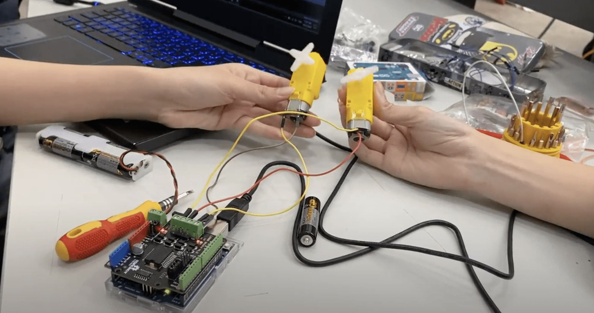
Motor
Conclusion to hardware for moving shoes: We did try to get cheap RC cars online, but the delivery took some time and when it arrived, we still had to spend time to figure out the hardware for it. We ended up using the DC motors because we already had a few DC motors available, and we could start with the Arduino programming right away.
DEMO: Motors moving in opposite directions & Motor with wheels
With the DC motors we had on hand, we first tested it out to make sure that it worked. For this, we did a simple code that controlled both motors based on keypress (using WASD layout). So for the shoes to turn left, we made the left motor stop and the right motor rotate in the clockwise direction, and vice versa for the shoes to go right (i.e. right motor stop, left motor rotate in clockwise direction).
Links to Documentation
Research references:
Interactive Devices
Indoor Positioning System