FOUNDATION 3D // DN1003 // PROJECT 3 – FOR EMIKO’S KIND
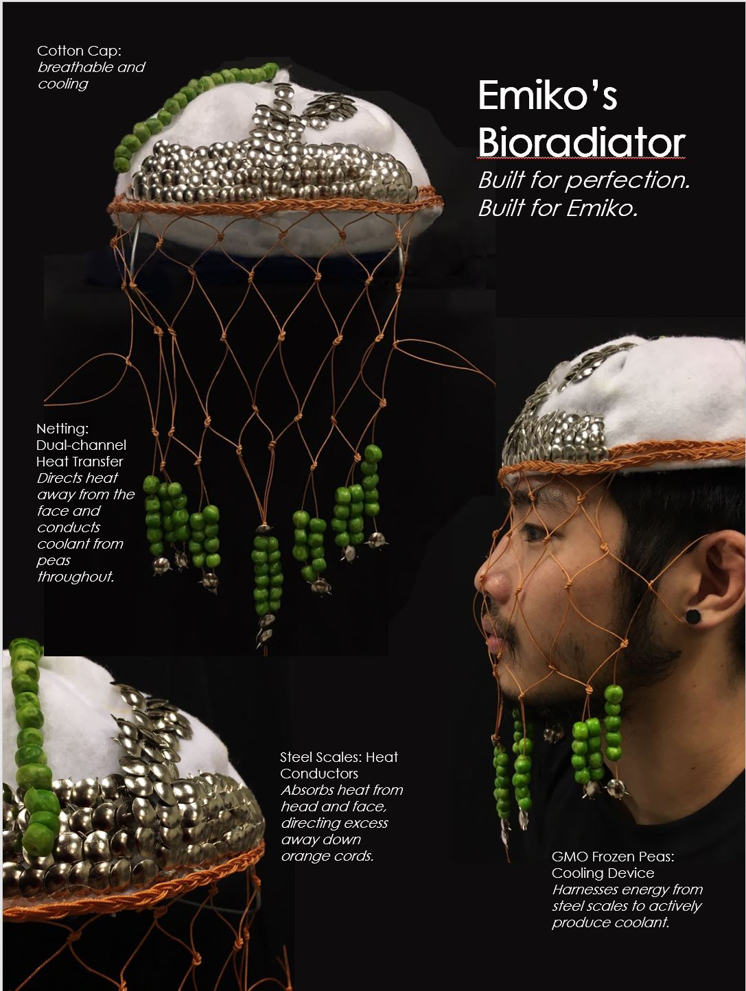
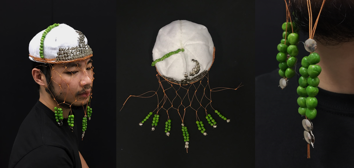
Emiko’s Bioradiator
Built for comfort, beauty and thermoregulation.
some subs
FOUNDATION 3D // DN1003 // PROJECT 3 – FOR EMIKO’S KIND
Built for comfort, beauty and thermoregulation.
FOUNDATION 3D // DN1003 // PROJECT 3 – FOR EMIKO’S KIND // PROCESS Continue reading “The Bio Radiator: Process”
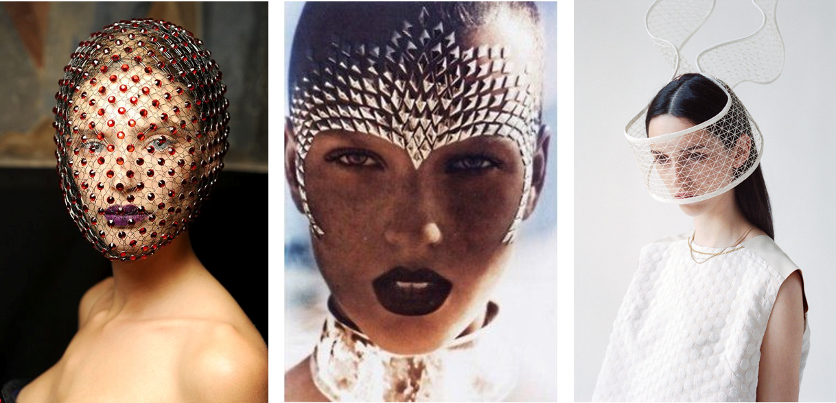
FOUNDATION 3D // DN1003 // PROJECT 3 – FOR EMIKO’S KIND // RESEARCH Continue reading “The Bio Radiator: Research”

FOUNDATION 3D // DN1003 // PROJECT 3 – FOR EMIKO’S KIND // MORPHOGENIC STUDIES


Initial experiments with koko crunch (I thought the koko crunch I bought was the original shape and not ‘koko’ koala shaped). This was not in reference to the tarpon scales but instead a SEM photo of a scaly plant.


Despite enjoying the final forms to the koko crunch webs, they did not resemble the original image clearly as the koko crunch pieces themselves had texture that distracted from the form.
I then proceeded to use thumbtacks instead as they had a smooth surface to form scales.
Different overlapping styles.

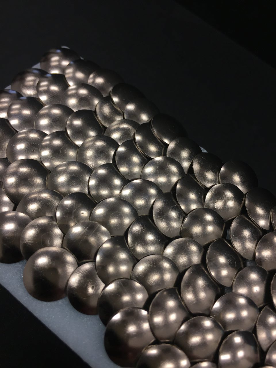


Upon closer study of the tarpon fish scales, I realised that the scales only overlap in rows and not adjacently.

With this in mind, I experimented with different materials as the base for the thumbtacks to attach to. I wanted the ‘skin’ to be a tactile form that could mould around something – so, I mostly used different types of fabrics.
Steps to secure thumbtacks to fabric:
(my little sister’s) DENIM (skirt) The denim material is thick and holds the tacks in place well.
Dishcloth made of a woven fibre. This dishcloth was thicker and the fibres were very closely packed. This made it easy to secure the tacks to the material, even without the glue . However, the cloth was stiff and did not convey the fluidity and “flexibility” of the skin that I wanted.
(an old) COTTON (t-shirt) Thought it was harder to arrange and secure the thumbtacks, the soft material offered the fluidity I intended for the ‘skin’.
A piece of thin foam covering. Good for securing tacks but bad for mimicking fluid cloth.
Spare black poplin from my mum’s scrap fabric box.
I made an approximately 20cm square of thumbtacks. It took around 18 tacks and 17 tacks for alternate rows. For the first few rows, I marked out the lines where the rows of tacks would go but because of inaccuracies, from the third row on I stopped marking out lines. The thumbtacks also varied in diameter which disrupted the pattern and created more mess further down the rows.
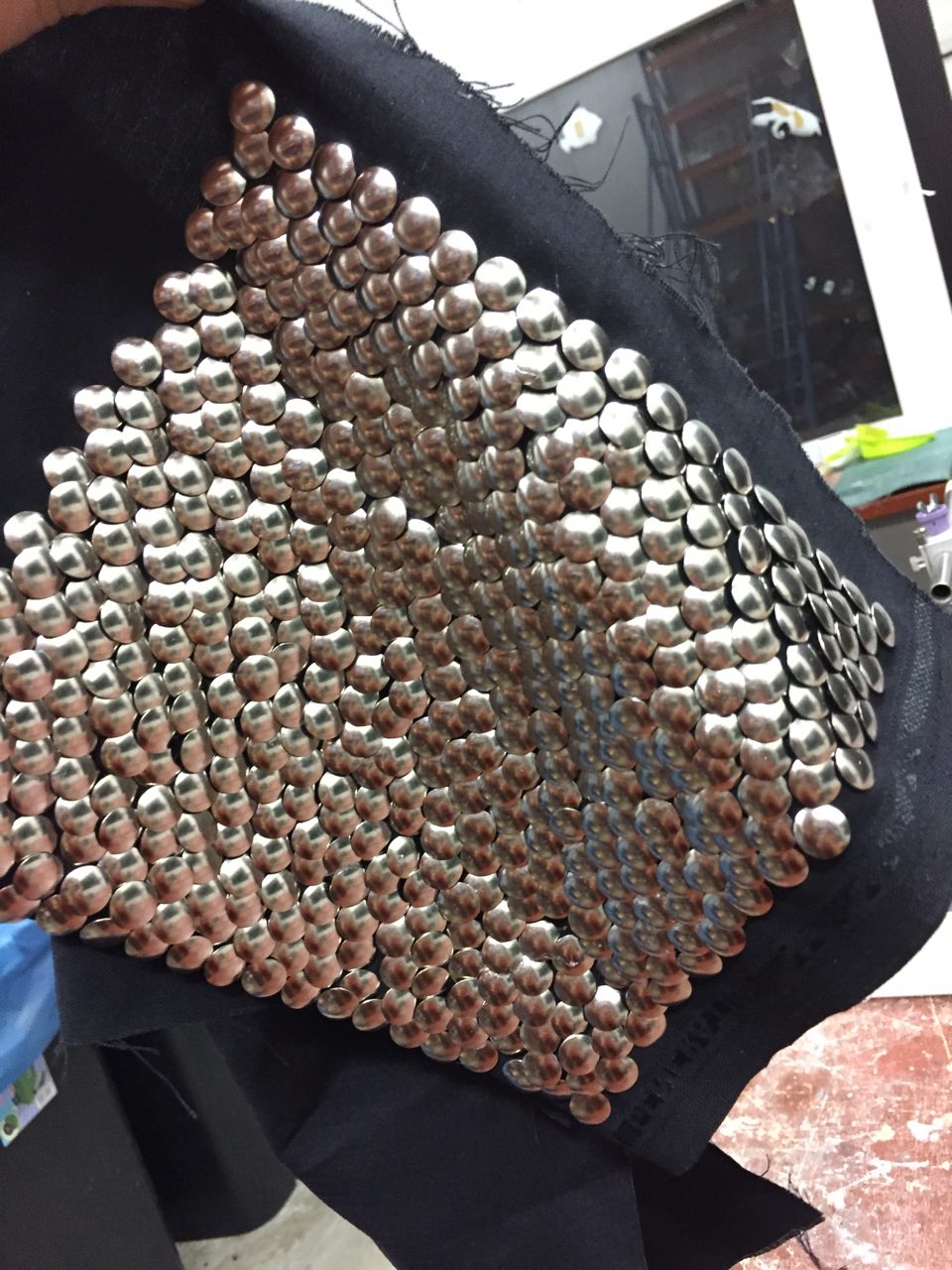
Securing the tacks was a difficult task as the impact of the hammer would break of the actual pin part of the thumbtack. An average of one broken thumbtack per row. Consequently, I tried to hammer the thumbtacks as little as possible to achieve the clamp on to the fabric. However, this resulted in a lot of loose tacks that needed more and more glue.
UHU glue also may not have been the best choice of adhesive as it is flexible and thus the pins of the thumbtacks managed to wiggle out of the glue hold. Despite this disadvantage, the glue’s flexibility allowed to fabric and thumbtacks to move and flow as I wanted, so I need to do more experimenting for the next part of this assignment.

FOUNDATION 3D // DN1003 // PROJECT 2 – EN POINTE Continue reading “En Pointe – Final Project”

FOUNDATION 3D // DN1003 // PROJECT 2 – EN POINTE // PROCESS Continue reading “En Pointe – Process”

FOUNDATION 3D // DN1003 // PROJECT 2 – EN POINTE // RESEARCH Continue reading “En Pointe – Research”
FOUNDATION 3D // DN1003 // PROJECT 1 – POLYHEDRON DREAMS Continue reading “Polyhedron Dreams: Final”

FOUNDATION 3D // DN1003 // PROJECT 1 – POLYHEDRON DREAMS // DEVELOPMENT

For the first model (Wire/Line), I referred to a net of a tetrahedron to give me an idea of how many equilateral lines made up the polyhedron.
Tetrahedron: 9 equal lines
At first, I used rubber bands to join chopsticks together in almost a tipi/teepee fashion. I marked out 2cm from each end of all the chopsticks in an attempt to keep all the sides even.
However, I realised that I could use the full length of the chopstick as they were all even in the first place.
I then applied hot glue in two different stages:
I chose hot glue as I preferred the accurate points of the tetrahedron to the crisscrossing that tying the chopsticks with rubber bands produced.
Result:

————————————————————————————————-
Approaching the planar model, I did not initially have a specific target or final sculpture in mind. Thus, I went with instinctual motions of trying to visualise the internal planes and try to create them physically.
This resulted in me marking four points on my wire model and sticking my ruler inside in an attempt to produce a shape as a plane. Proving to be an extremely inaccurate method (especially due to the lack of protracters on hand), I decided to find a better technique in creating planes.

In my second attempt, I used tape to mark out where I wanted my planes to exist in within the wire model. From this, I found that this is a more accurate way to measure and visualise the planes. Without a compass on hand, I resorted to laying pieces of paper against the taped lines and cutting rough templates of the triangle in order to achieve a semblance of the angles within the triangle.
Additionally, I decided to use tape because it allowed me to visualise and measure intersections between two planes. This helped me to cut slices into the planes to create interlocking pieces of cardboard which attributed to the sculpture being self-supporting.

This new technique was successful for the first two planes as shown below. However, I struggled to add a third plane into the sculpture and the more attempts made, the more unclear how the sculpture would represent the internal volume of a tetrahedron. I decided to scrap this and rethink my approach towards achieving the internal volume of the model through planes.
Perhaps two planes would have been enough, but I felt that it did not show the whole volume tetrahedron as it barely touched any of the apex points of the shape.

2. Tape guides that fell apart.
3. I wasn’t sure where the third plane would fit in.
After taking a step back and looking through the provided references (Lygia Clark), I took a more measured and geometrically accurate approach.
As the original wire model had 20cm sides, I started with an anchor isosceles triangle of sides 12x20x12cm and based the other planes from there.

I taped the faces together section by section and kept struggling with one planes. It was possibly due to an error in measurements but I enjoyed the new dimension this gave to the work. This missing piece forced an asymmetry in the work and resulted in more interesting angles to view it with.

After taping the planes together, I realised in its current form, it was purely supported by adhesive. I then decided to add an element of interlocking with smaller shapes with a maximum length across of 2cm.

I cut 2cm deep grooves into certain planes in order to accommodate the slices.

This gave the work an almost futuristic aura to it with its simplicity in shapes and clean cut lines.
Measurement guides (not to scale)

Final product:
————————————————————————————————-
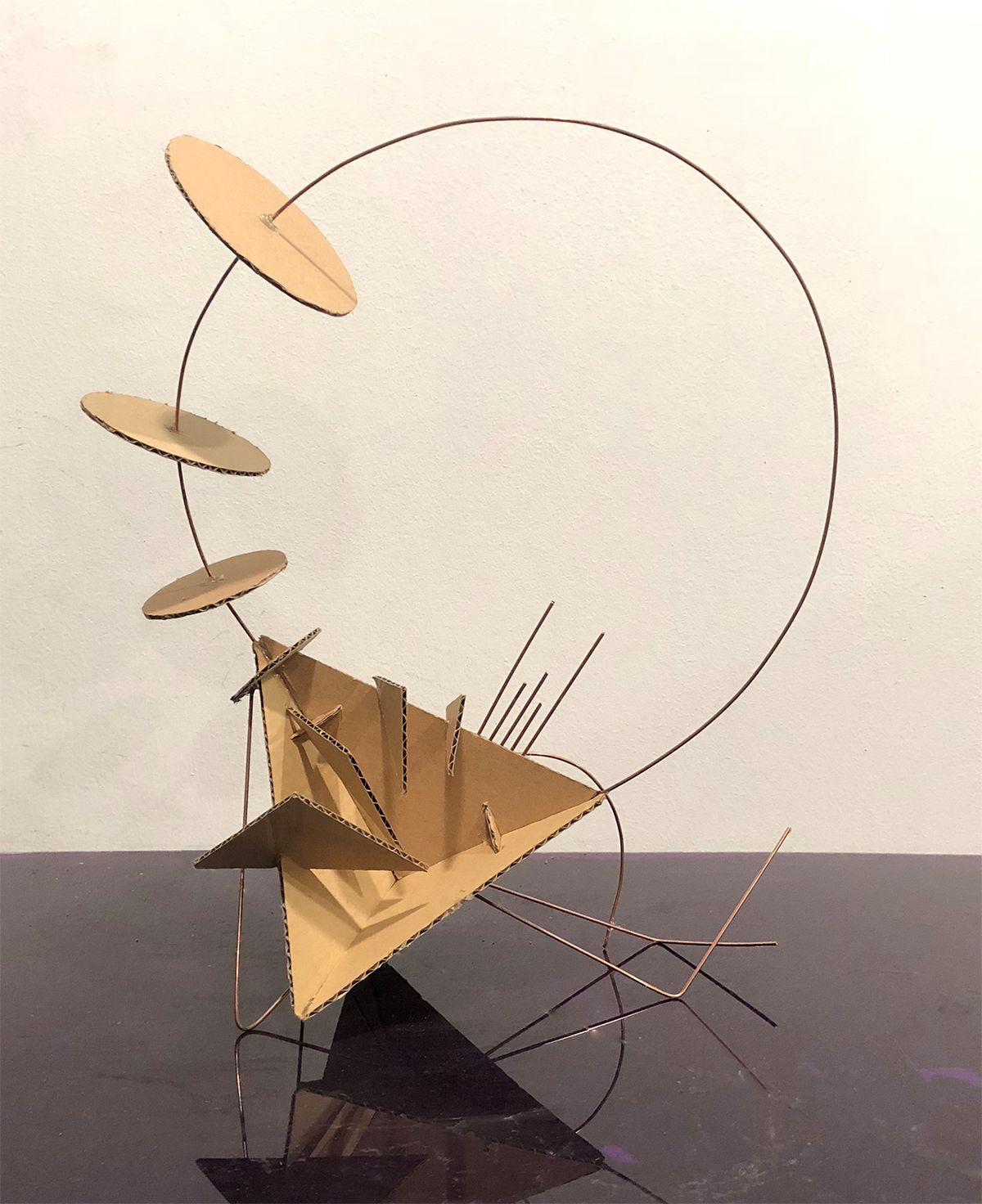
I started on the third model by adding elements to a replica of the planar model. After some consultation, I decided to focus on the small slices and expand on them as focal points on their own. I had the picture of the circle and triangle extrapolating out as if the model was phasing out and away from itself.


I started with the circles:
To transition between the base tetrahedron and the ‘outer’ circles, I added a disc of 4cm in diameter that intersected with the near point of the planar model. I then cut out circles of increasing diameter (6, 8, 10cm) and pierced the centres through with a wire.

I glued them in place at about 3cm apart from each other and held the sliced cone where I wanted to attach it. From this, I realised that the wire was too thin and not strong enough to support the discs without more reinforcements.
In an attempt to figure out how to counter this drooping wire, I cut a longer piece of wire and was going to double line the circles. However, when slotting the start of the wire into the base model, I noticed the resting position of the wire gave a very graceful curve and that this curve provided enough resistance to keep the discs upright.

I then recreated this curve with a sturdier wire (copper) by slowly bending it and around different objects (including Mayle’s waist). This proved to be a better choice as it not only held the discs upright, but it also created a stronger presence of line in the line and plane model.

Moving on to the triangles:
I wanted to stray away from the same idea of the shaped extrapolating out of the base model and rather experiment with having this extrapolation almost curve along the edge of the tetrahedron. Again, I used increasing sizes of triangles (with heights of 4, 6, 8, 10cm) and interlocked them onto one ‘face’ of the model.
On the other face, I wanted to incorporate lines of copper wires:
I added to ‘legs’, mimicking the other adjacent cardboard triangles and decided to add some asymmetry in another straight line connecting the floating triangle to one leg as well as a semicircle to weave in some harmony with the extrapolated discs.

After understanding some essentials in interesting sculpture:
Anchor
Subdominant
Subordinate
I attempted to now find an appropriate subordinate to the model after recognising the anchor being the base tetrahedron and the subdominant being the large circle lined by the loop of copper wire.
I started with a cuboid shape out of copper wire and tried to find different ways to incorporate it into the model. The best result was propping the model up, but after deliberation, I realised the reason why it was better was because of the tilt the wire cuboid created.

I then added some new spokes to the model to create a tilt where it would rest back on the triangular legs. These spokes were bent at a 90-degree angle and I realised I could use the holes of the corrugated cardboard as points to insert the wires into.  I added to spokes and then an additional 3 wires pieces of short wire next to them to create some visual harmony.
I bent the ends at first to mark out where I wanted to cut the wires (as that length provided the desired tilt) but I liked the way the bent wire directed the eye back up to the loop.
I also re-placed the semi-circle to bring the sculpture together as I felt that one face of the model was very plane.

FOUNDATION 3D // DN1003 // PROJECT 1 – POLYHEDRON DREAMS // RESEARCH Continue reading “Polyhedron Dreams: Research”