The first 2 functions that came to my mind with this was blobs and jit.lcd, and I will try my best to make it work!
To-do list:
01 Blobs to jit.lcd
Initially, I wanted to link blobs to the mousedrawing patch under jit.lcd, to make use of the threshold to detect light and then using light to draw. But linking blobs.centroids.draw to jit.lcd was probably a bad idea, since MAX kept crashing every time I tried to have them both toggled on at the same time. I also tried deconstructing the mousedrawing patch to see if it could work with blobs, but it somehow doesn’t.Then I tried using suckah to link to cv.jit.threshold and jit.lcd. Suckah allows us to take a pixel from the display and link the detection to other functions. Nothing happened when I linked the displayed image directly to jit.lcd. I managed to link up suckah and jit. lcd using the same color tracking patch which Jace and I used in our final project. It seems to be working quite well, but only displays squares on jit.lcd for now.
I tried changing the squares to other shapes under the colourtrack patcher, but probably because I was using a flashlight and not a laser, it still couldn’t work.
Having to work on this assignment without a webcam, one of the coolest things that I discovered was that our phone can actually be used as a “webcam”! This makes camera-related assignments a lot more convenient, and can be used as substitute if we need more cameras in our MAX MSP projects in future.
Okay now, moving onto the project!
To do list:
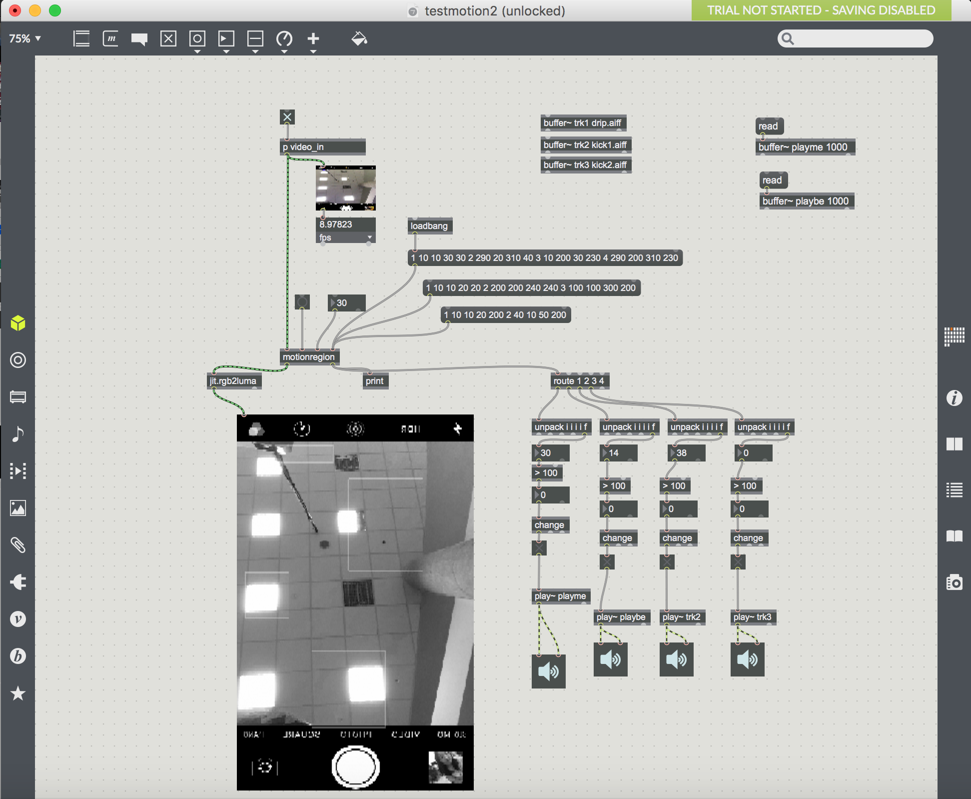
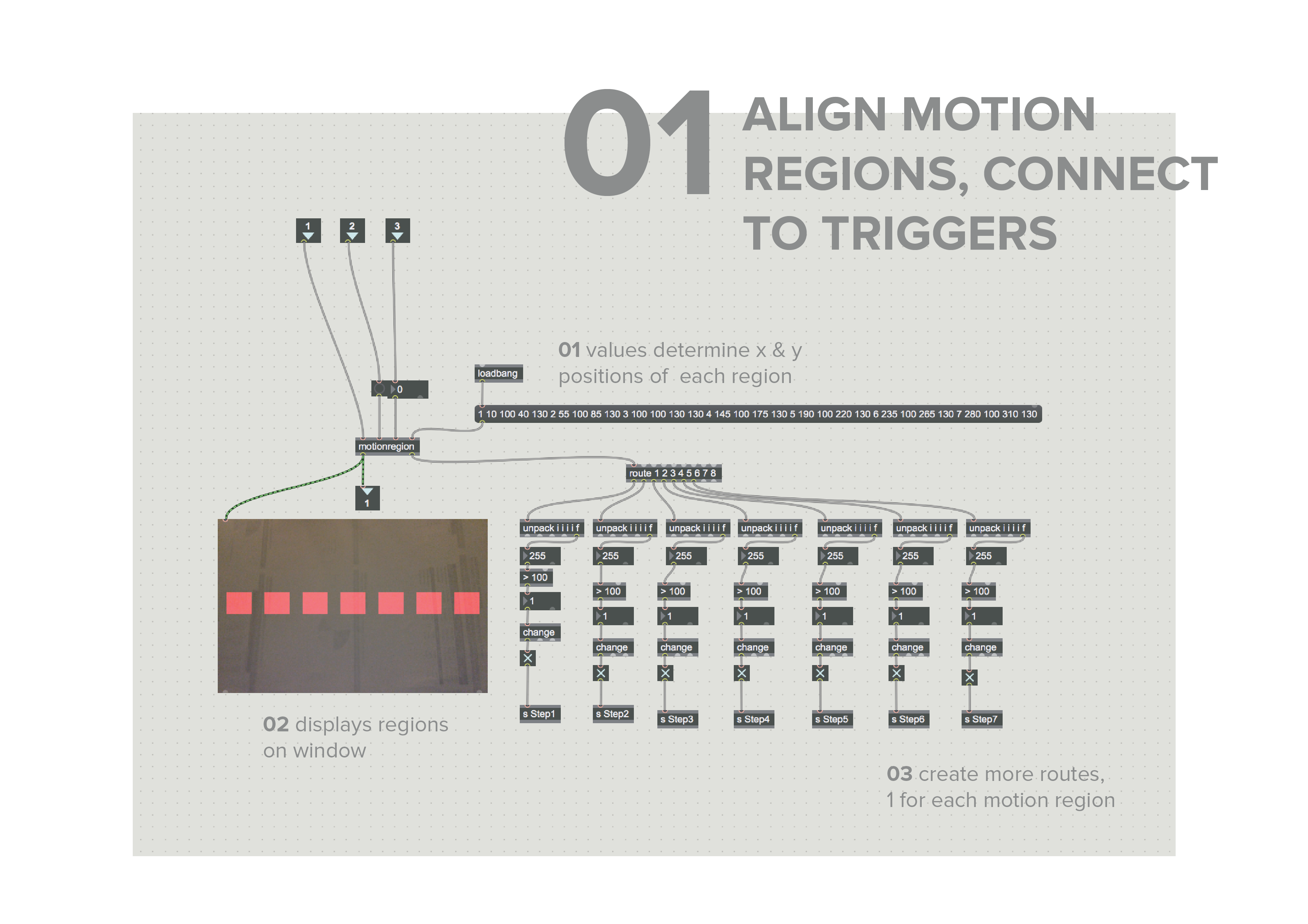
01 Align motion regions, connect to triggers
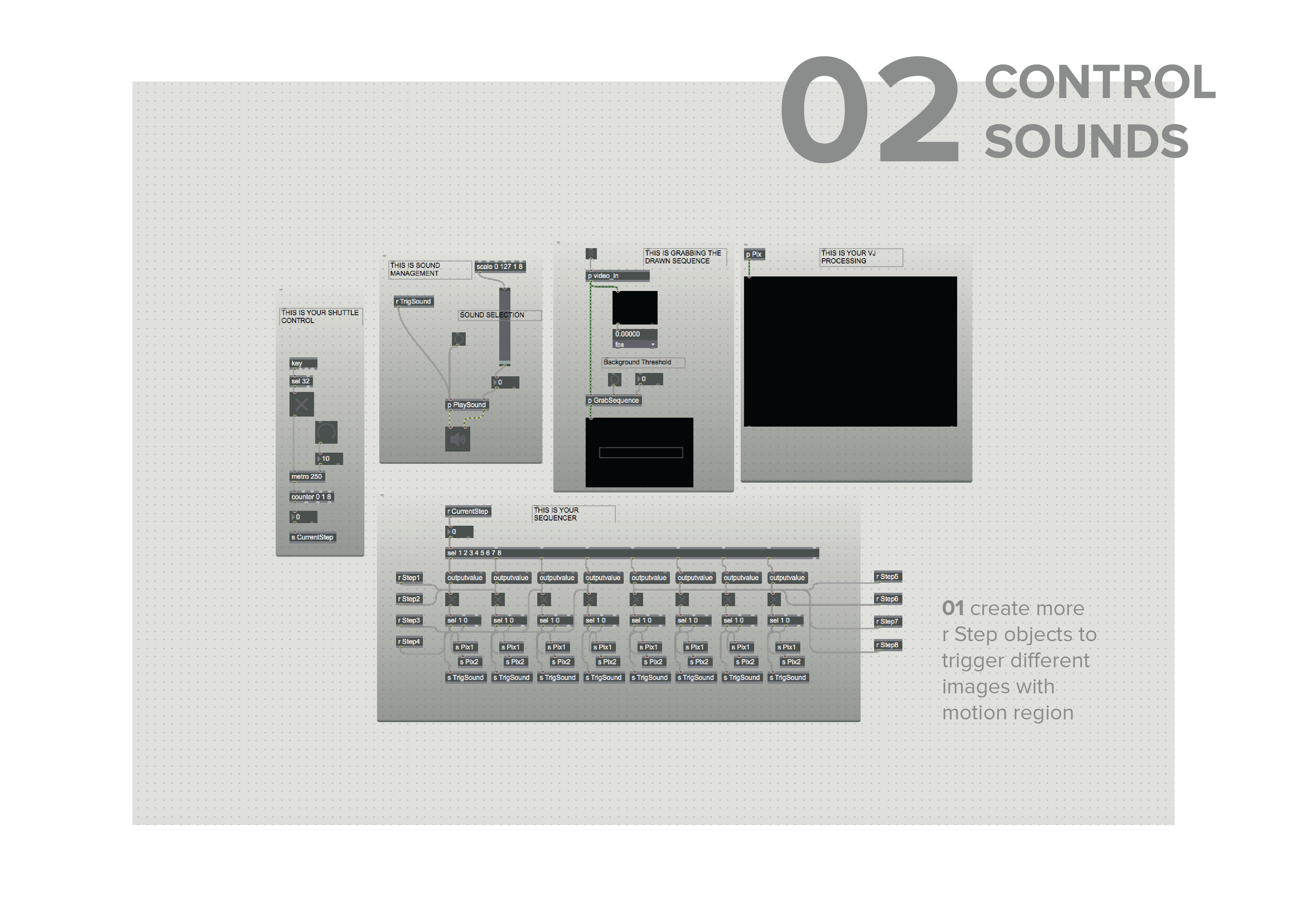
02 Control sounds with motion regions
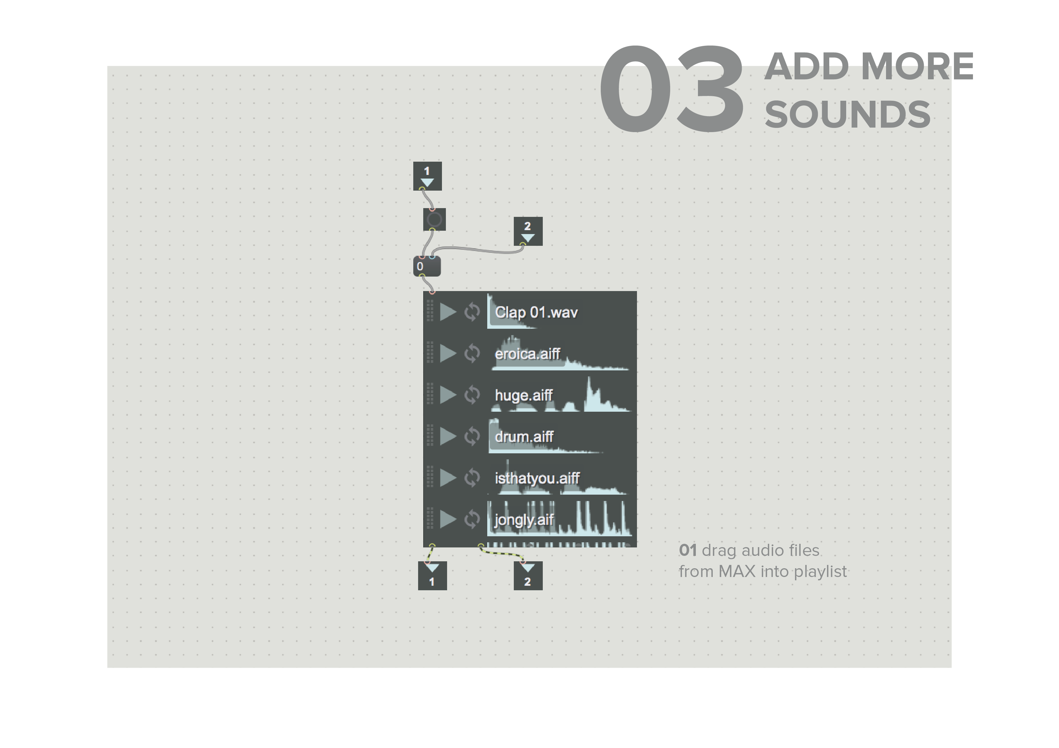
03 Add more sounds
To be able to trigger 8 different sounds, we first have to create multiple boxes by using x & y values to position each of them in a message. I had quite some difficulty figuring out the distances and sizes of each box such that all of them will fit in a row. However, I realised that it might be easier to have them not all in the same position so that the detection would be more accurate. The boxes are then displayed on a p window, showing the areas where the motion regions are. To allow the motion regions to function as detectors, more routes have to be added and linked to an output in the main patch.On the main patch, the motion regions are linked using s Step & r Step, functions that enables data to be sent and received within the patch and makes it neater. Initially, I linked every output value alternatively to r Step 1 & r Step 2, but I realised that only 2 motion regions were connected. More r Step objects had to be added to enable the other motion regions. I tried testing if the motion region works with the triggers first:
To add more sounds, simply drag in audio files built within MAX from the left bar, and pull it into the playlist. The sounds are triggered in order and can be controlled by the slider on the main patch.
But somehow, although different motion regions were triggered, they all kept playing the same sound. I’m not sure if there was something wrong with the patcher or with the s TrigSound & r TrigSound objects, but I could only play different sounds by pulling the slider. I tried connecting it to r CurrentStep, thinking that the values were displaying which motion region was triggered.
The sounds started playing immediately after i turned on the speaker output, and I realised that it was not linked to motion region at all. (I’m still not sure what it is for)
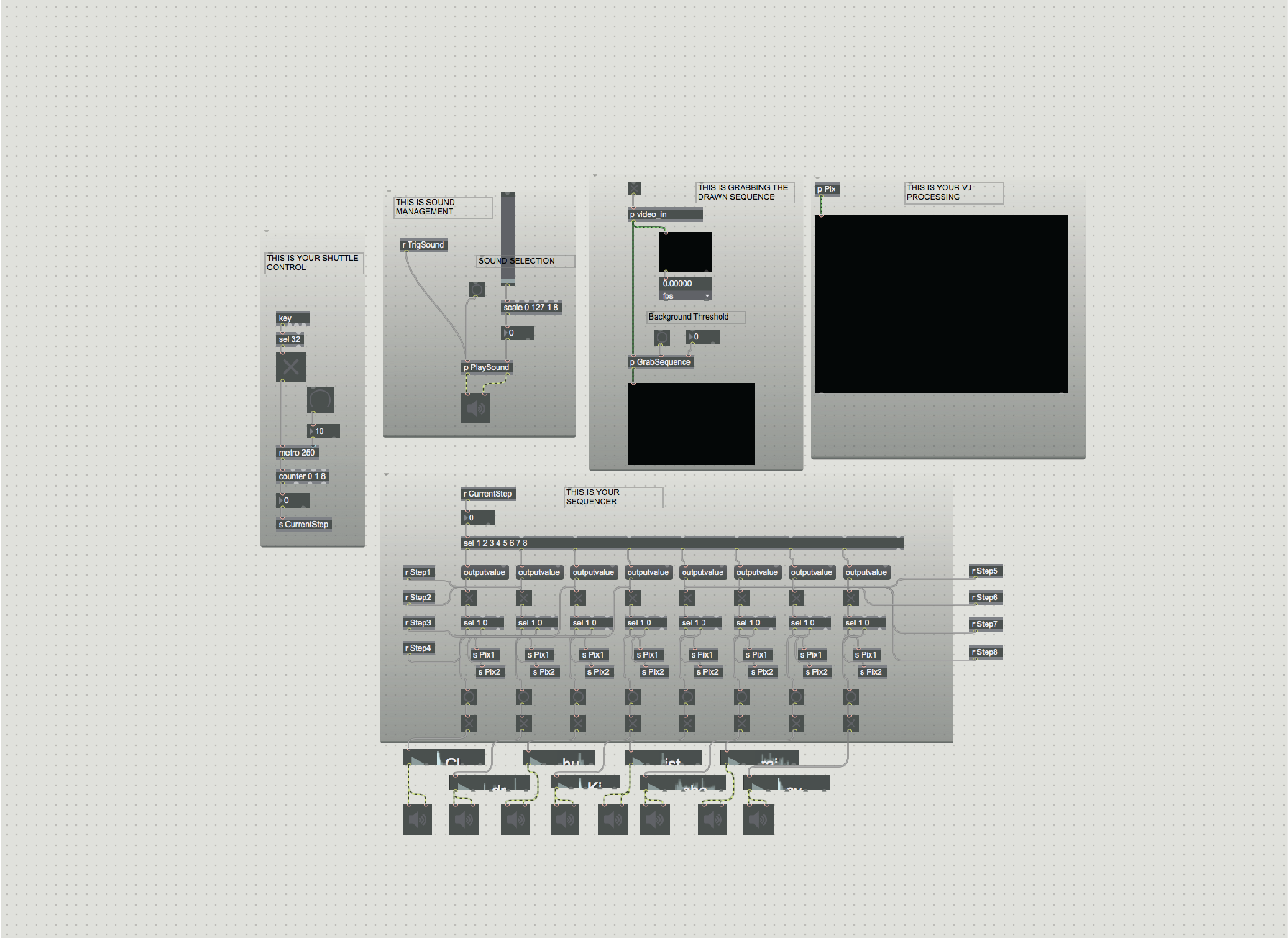
After playing around and attempting to connect the r TrigSound in different ways, I realised that it doesn’t send any value through at all, and only sends a bang to the playlist, causing it to only play 1 sound all the time. Hence, I put aside the playlist and decided to connect all the sounds individually to the output values instead.
I can’t seem to figure out why r TrigSound is unable to play the audio files according to the audio on the playlist, and will work on finding it out!
For this assignment we had to place a face over ours and try to make it as blended as possible, but I was wondering what it would be like if I was able to “create” my own face instead? Through this I discovered the jit.lcd function, which basically allows you to draw with your mouse on MAX.
To-do list:
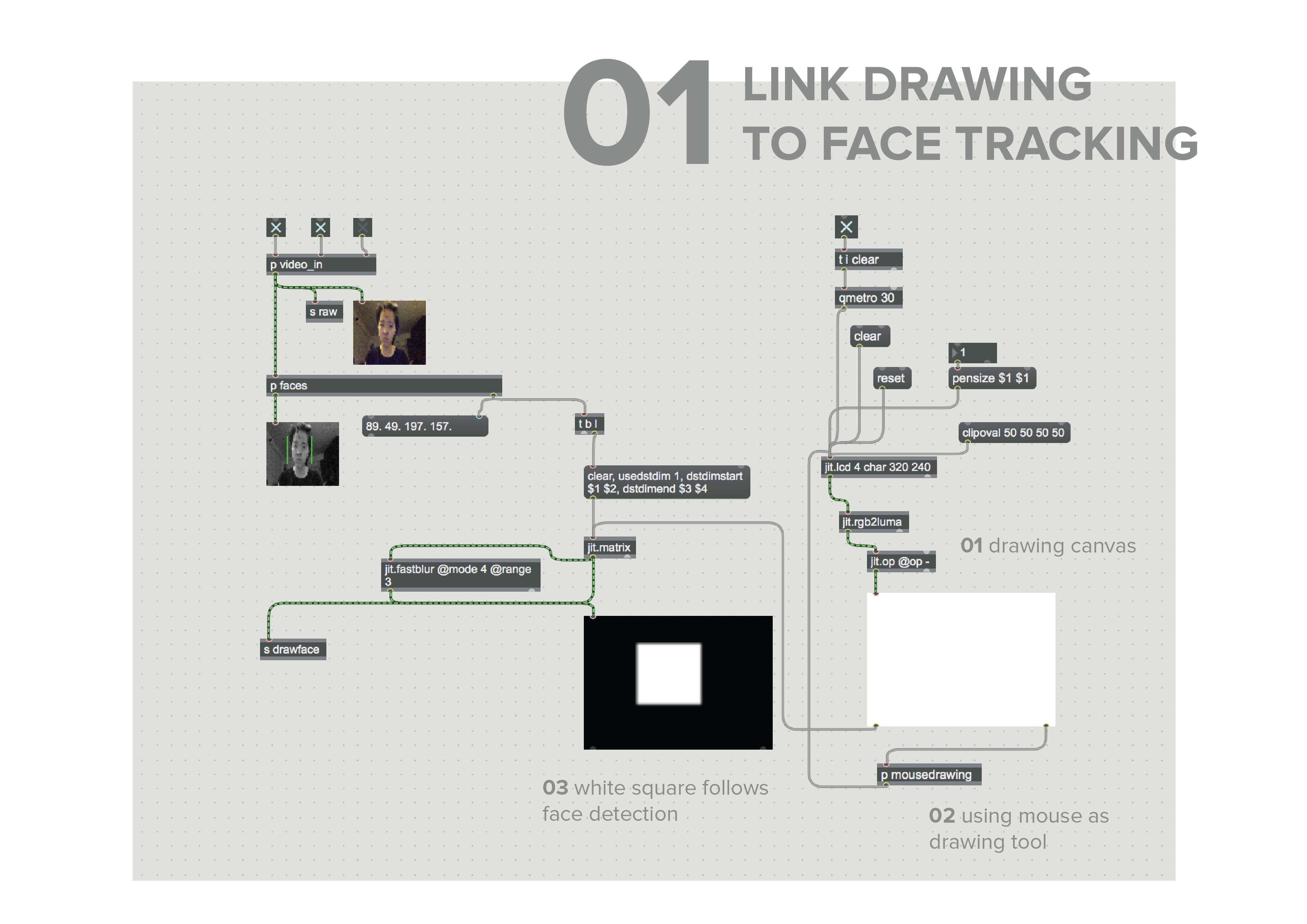
01 Link drawing to face tracking
02 Crop image onto face
Initially I was having difficulties with finding out where jit.lcd should be placed. When I linked it to p faces (where the face tracking functions are) and attempted to jit.alphablend the image from the camera and from jit.lcd, the combined image just kept flickering. Working from the Step 1 file that LP provided, I extracted everything onto the main patcher and replaced the image file with jit.lcd so that it could be connected to other functions as well.
02 CROP IMAGE ONTO FACE
I wanted to make sure that the drawn image was only mapped onto the face. I searched online and found that there was a message called clipoval which can help to keep drawings within an oval dimension on jit.lcd. I thought this would be ideal for what I was trying to achieve, but sadly it doesn’t seem to work. The closest I could get was to remove the clear function from the mapped square that was linked to the captured camera image, such that it will leave a trail wherever my face moves, “erasing” the darker parts and creating the impression that I was only drawing on my face.
However, it still doesn’t create a very clean image, and trails of the drawing can be seen at parts where my face cannot cover. Unfortunately, this is the closest that I have managed to get with this, but I am quite determined to figure out the issue with the cropping.
In our first lesson with Max, we were tasked to do three things to achieve Christian Moeller’s Electronic Mirror effect, whereby the mirror fades to black when a user approaches it, only showing them a clear reflection when they are at a distance.
To-do list:
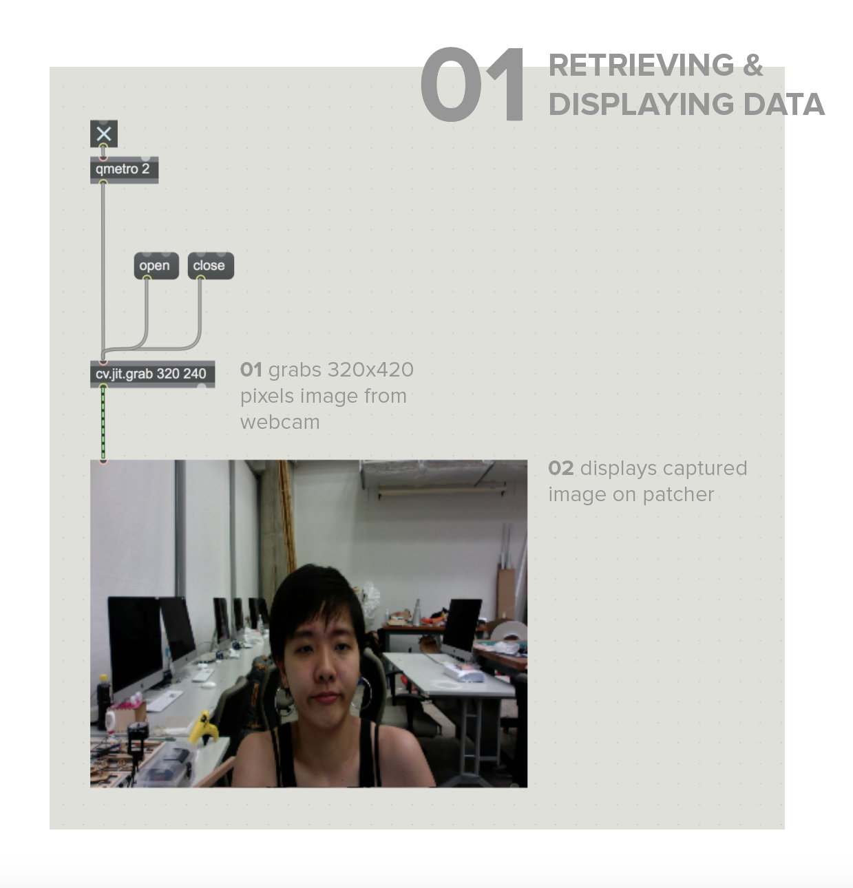
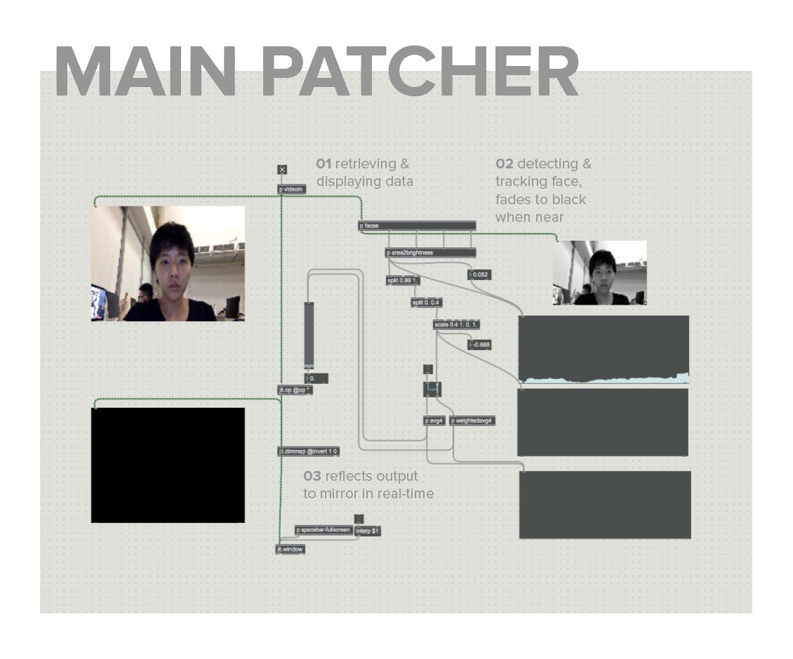
01 Retrieve & display data from webcam
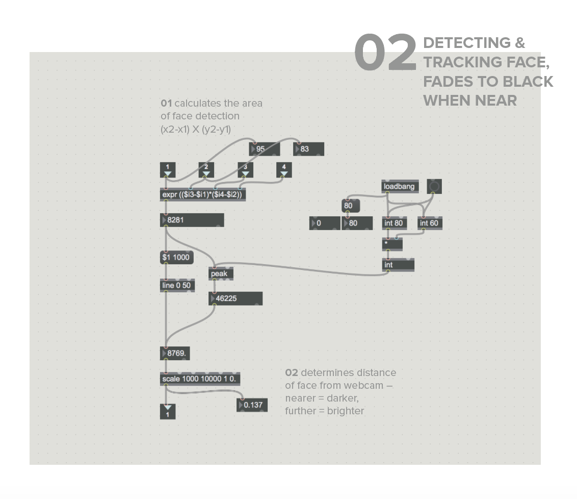
02 Detect & track size of face + fades to black when near
03 Reflect the output so that it reacts like a mirror
Within p videoin, the functions were kept simple – to only control the flow of input from the webcam using the open and close functions. The image is sent onto the patcher using jit.pwindow, so that we can visualise what is being captured.
To determine the area of the face, we calculate the position using the maximum values of position x & y. This value is then sent through 2 outputs, the first is to $1 1000 & line 0 50 to smoothen the transition of brightness within 50 milliseconds. The second output is through peak, which tracks the nearest distance that the face was to the camera (aka highest value). The values are then sent through scale, where the maximum and minimum values for distance & brightness is adjusted. In this case, we can change the gradient from bright (1) to dark (0. <), at a distance of 1000 to 10000.
After running through various jit. functions, in an attempt to find one that could invert the image, I finally landed on jit.dimmap, which inverts the output screen. However, it was flipped on a vertical plane, instead of horizontal as I wanted it to be. By including the invert value and playing with the 1 & 0 values through trial and error, it finally reflected to mirror my movements.
E X P L O R A T I O N S
Initially, I tried experimenting with other functions to adjust brightness because the original file looked really complicated and I found it difficult to comprehend what was going on with all the splitting of values. After running through the jit. functions (and getting distracted by many cool things along the way), I landed at jit.brcosa, which adjusts an image’s brightness/contrast/saturation. I soon realised it was not what we really want to achieve here, but it’s worth a try anyway!
Although the transition was not as smooth yet, using jit.brcosa overexposes the output quite drastically.
I tried fiddling with the values and overexposed my face till it was the same white as the background (which is pretty horrifying), but I also realised I was able to change our control by inverting the values and having the image brighter when closer, and darker when further.
In an attempt to smooth the constant flickering, I added an object and typed “smooth”, hoping some magical function would appear. And sure enough, I found Smoothr (no surprise there). This replaces the original method using scale, and also visualises the values in a graph. Although it seems to smooth out quite evenly, the fading seems a bit too slow and obvious.
Changed the smoothing value and it works much better than before! Will definitely work on improving this further and try out other methods of using faces to trigger other changes.

 Then I tried using suckah to link to cv.jit.threshold and jit.lcd. Suckah allows us to take a pixel from the display and link the detection to other functions. Nothing happened when I linked the displayed image directly to jit.lcd. I managed to link up suckah and jit. lcd using the same color tracking patch which Jace and I used in our final project. It seems to be working quite well, but only displays squares on jit.lcd for now.
 Initially I was having difficulties with finding out where jit.lcd should be placed. When I linked it to p faces (where the face tracking functions are) and attempted to jit.alphablend the image from the camera and from jit.lcd, the combined image just kept flickering. Working from the Step 1 file that LP provided, I extracted everything onto the main patcher and replaced the image file with jit.lcd so that it could be connected to other functions as well.