concept
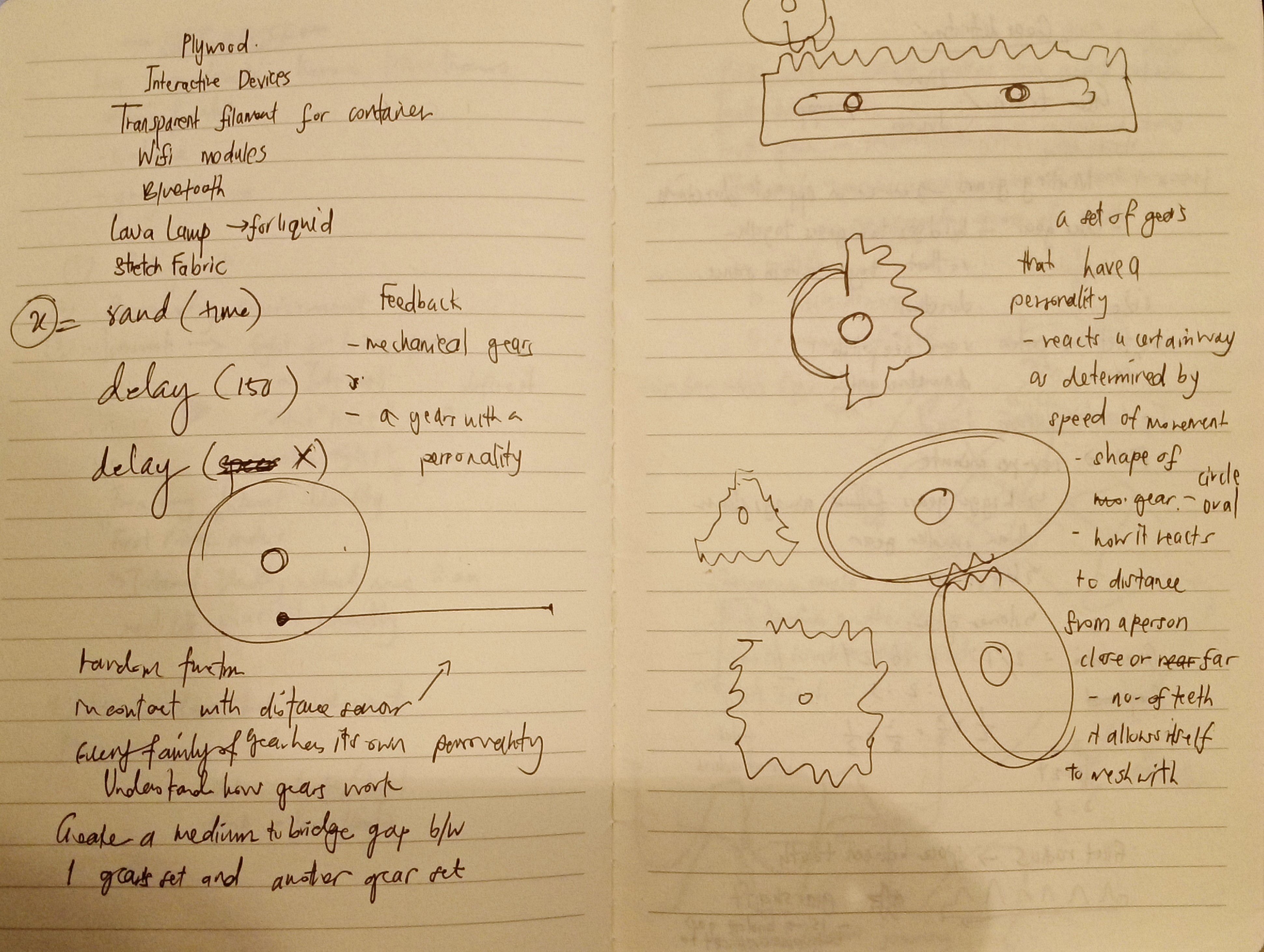
As a follow-up of my recent mid-term project, which makes use of threads to represent the places people in NTU have visited around campus, I decided that there would be a better use of materials in representing a digital form of my concept. Without venturing too far off the use of circles, and cyclical nature of how human relations are formed, I thought that using gears that move would be best suited for this final project.
As gears are normally fixed with other gears, and moves according to how its neighbors move, this was a direct way of representing how one thing leads to another – similar to how relations are formed through communication and interaction between one or multiple people at the same time. Also, the type of interactions we have with people can trigger various forms of reactions – emotional reactions I would say. By trigger it could mean a dialogue, a presence, the level of closeness with a particular person evokes certain emotions that range from pleasant to unpleasant. This would mean that every person’s reactions are personalized according to such variables when presented at that.
(add video of two family of gears moving at different speeds )
In the video clip above, I basically showed Kristy and Biju about my progress in using gears – playing around with the delay, speed of movement using Arduino software. It was highlighted that some gears had different “personas” to these gears, it would in a way, represent gears which are “personalized”.
At the same time, there were several more ideas that came to mind in use of materials and technologies used, where an the interactive element could be formed by adding a sensor. With the use of distance sensor this would show the viewer’s interaction with the said personalized gear – that would trigger reactions in both the viewer and gears too. And when we tie this back concept, it does show some relationship aspect in representation of gears.
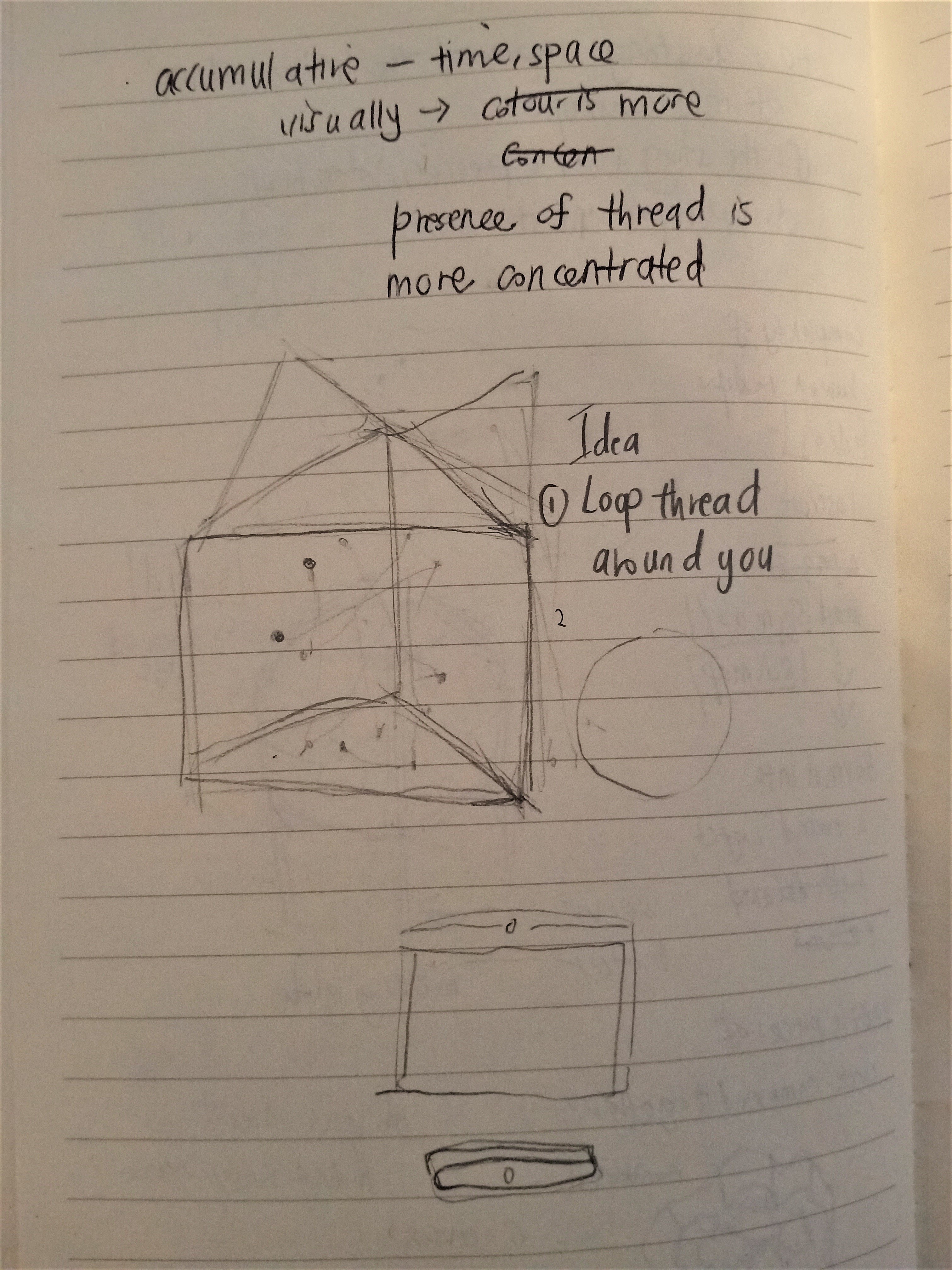
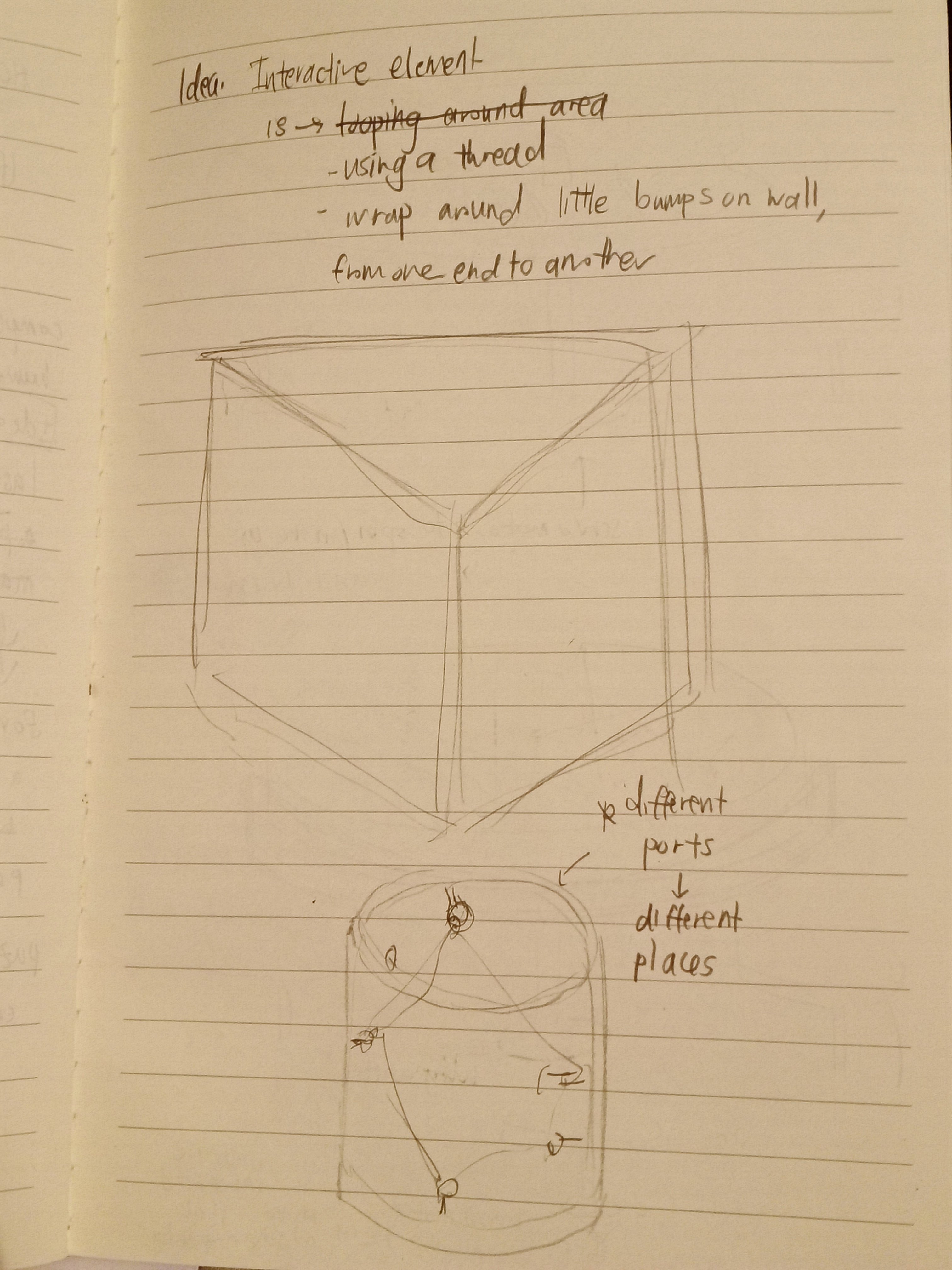
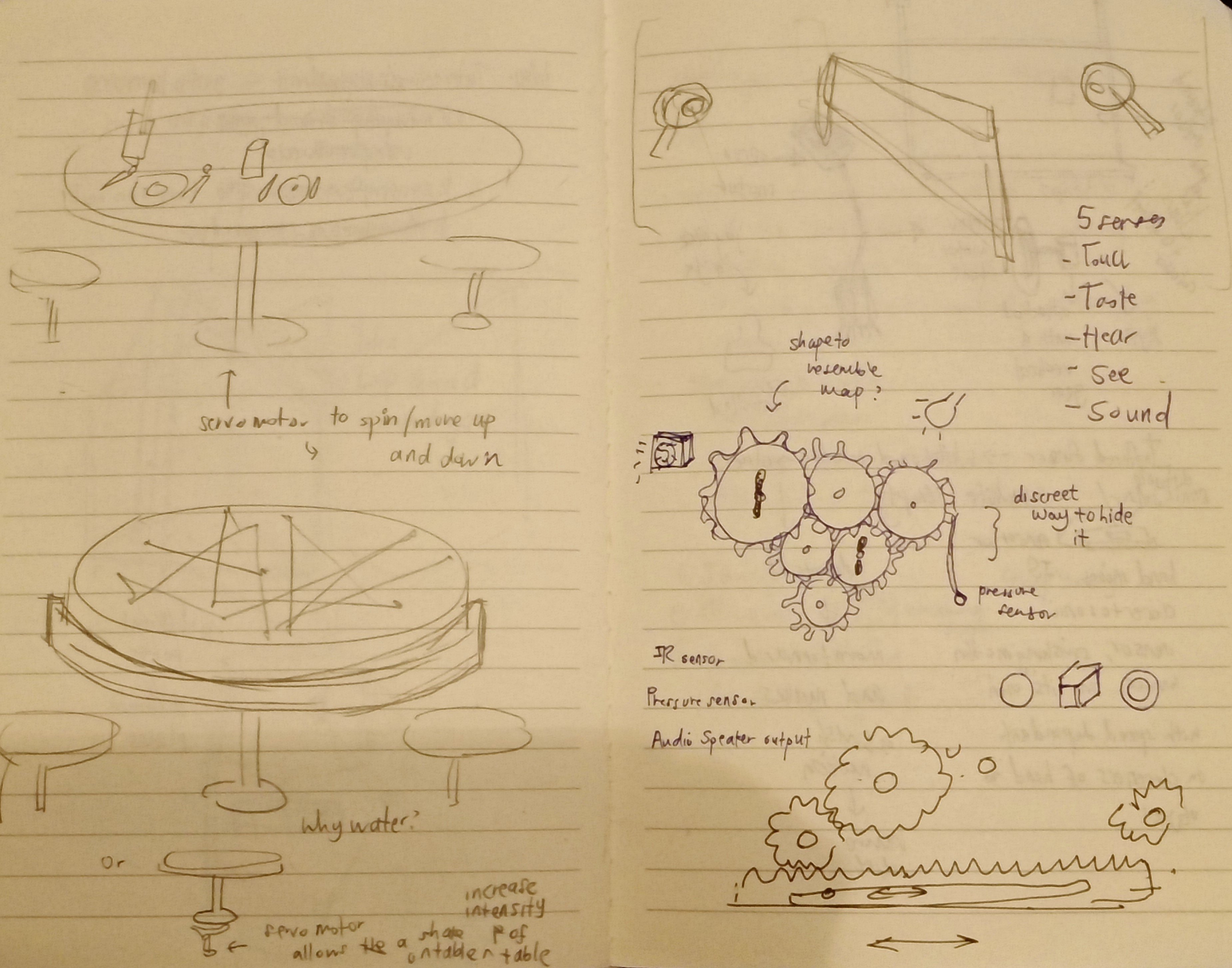
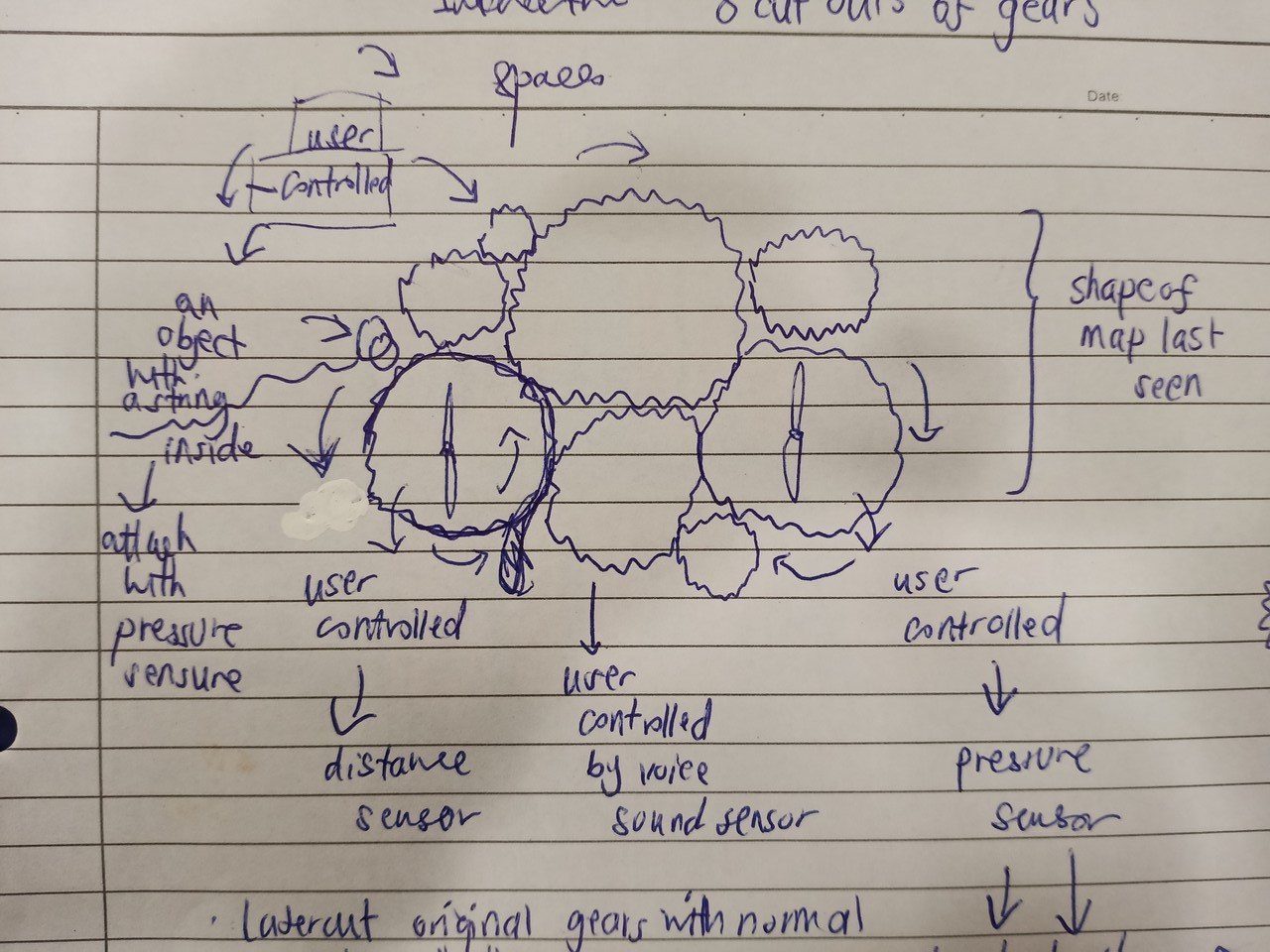
drafts/ideas to show concept
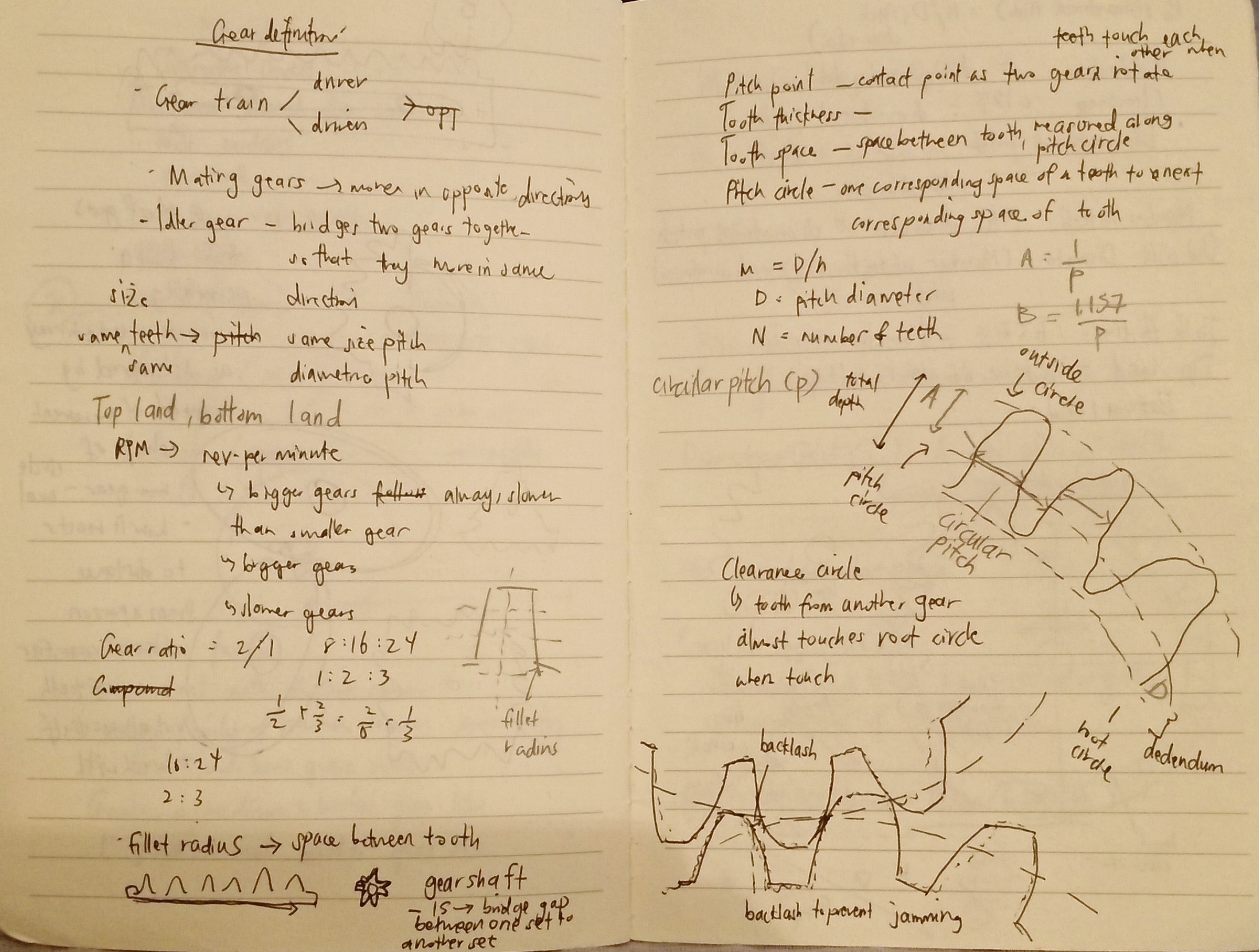

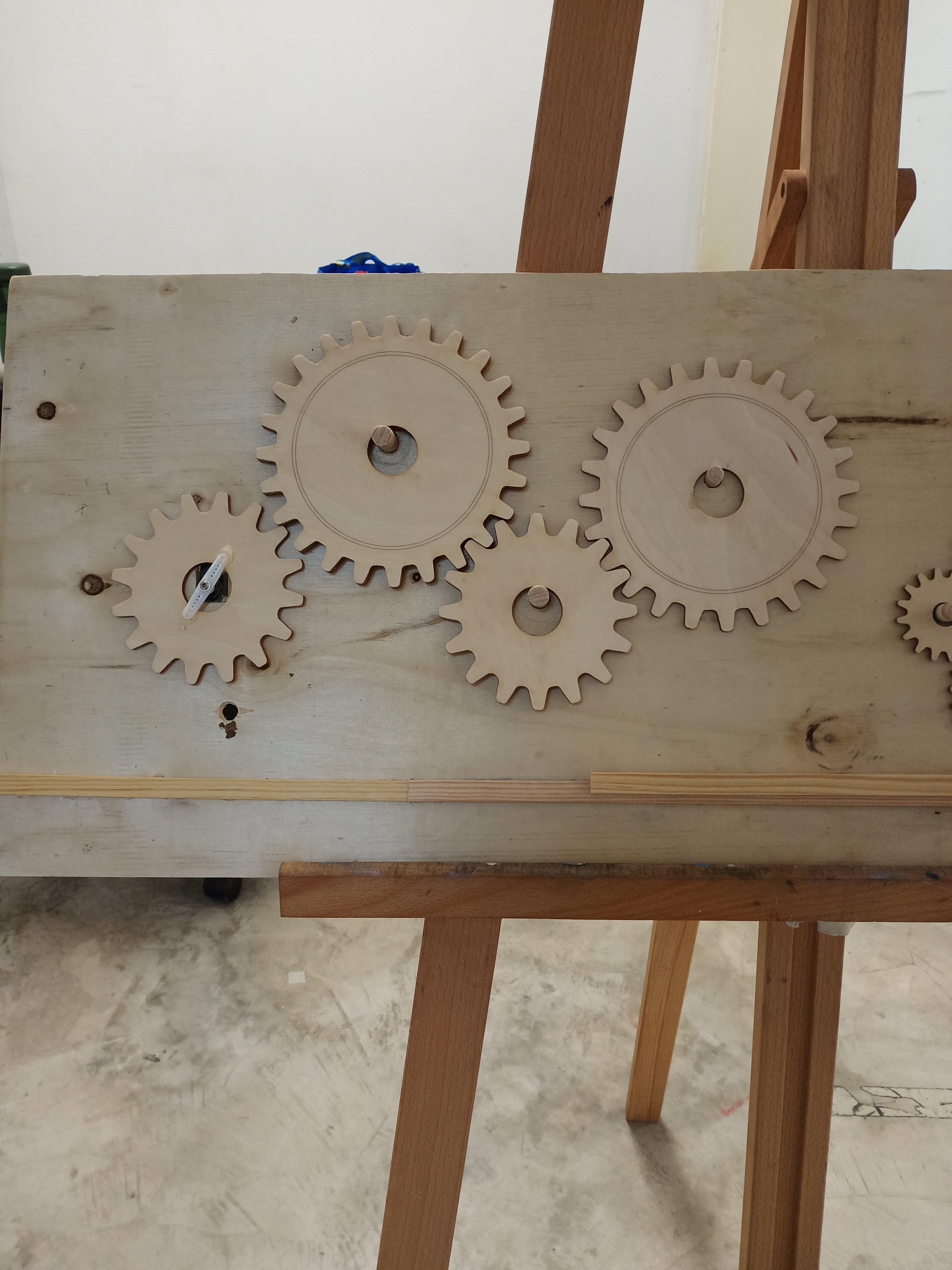
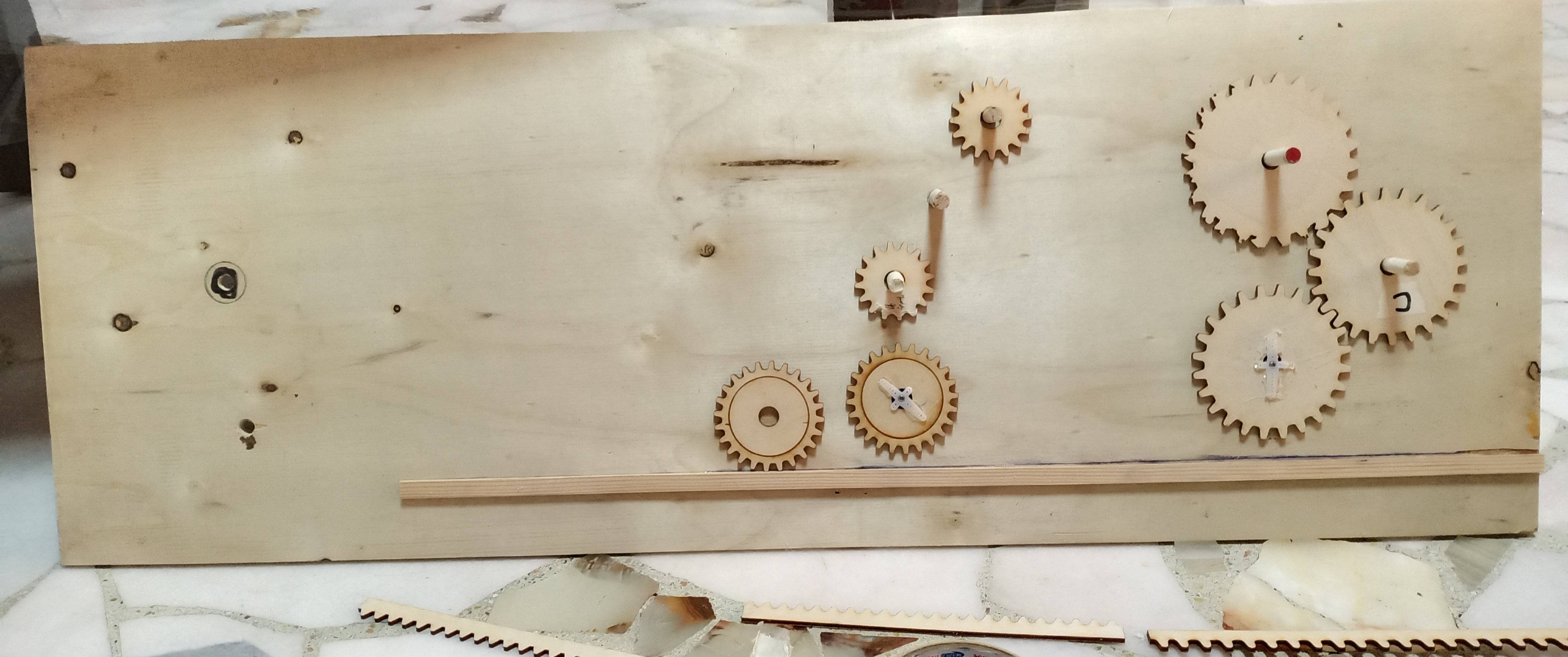
process of making gears
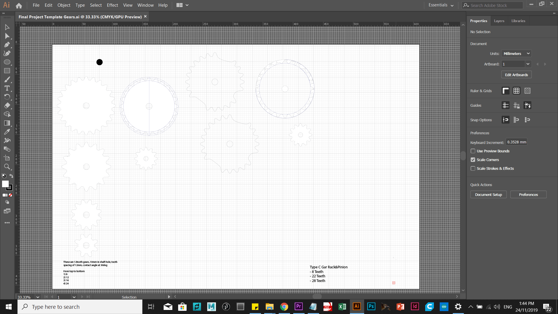
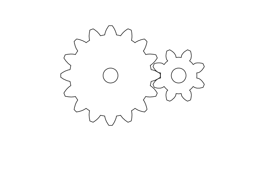
This was the website I visited to get accurate measurements of the gears that I wanted. https://woodgears.ca/gear_cutting/template.html
I was able to get customized version of the gears that I wanted – from tooth spacing, number of tooth, rack&pinion ( which would be used eventually) and this helped a lot in making and “image trace” these images into Adobe Illustrator. Afterwards, I laser cut them in 3 mm thick plywood in the laser-cutting room at ADM Level 2. Prior to using gear generator, I simply took images off google – but that was not the best option, especially considering you do not know the exact measurements of the said gears. Hence, with my limited amount of budget for purchasing expensive plywood, it would be best to be precise with what gears to add in your Illustrator file.

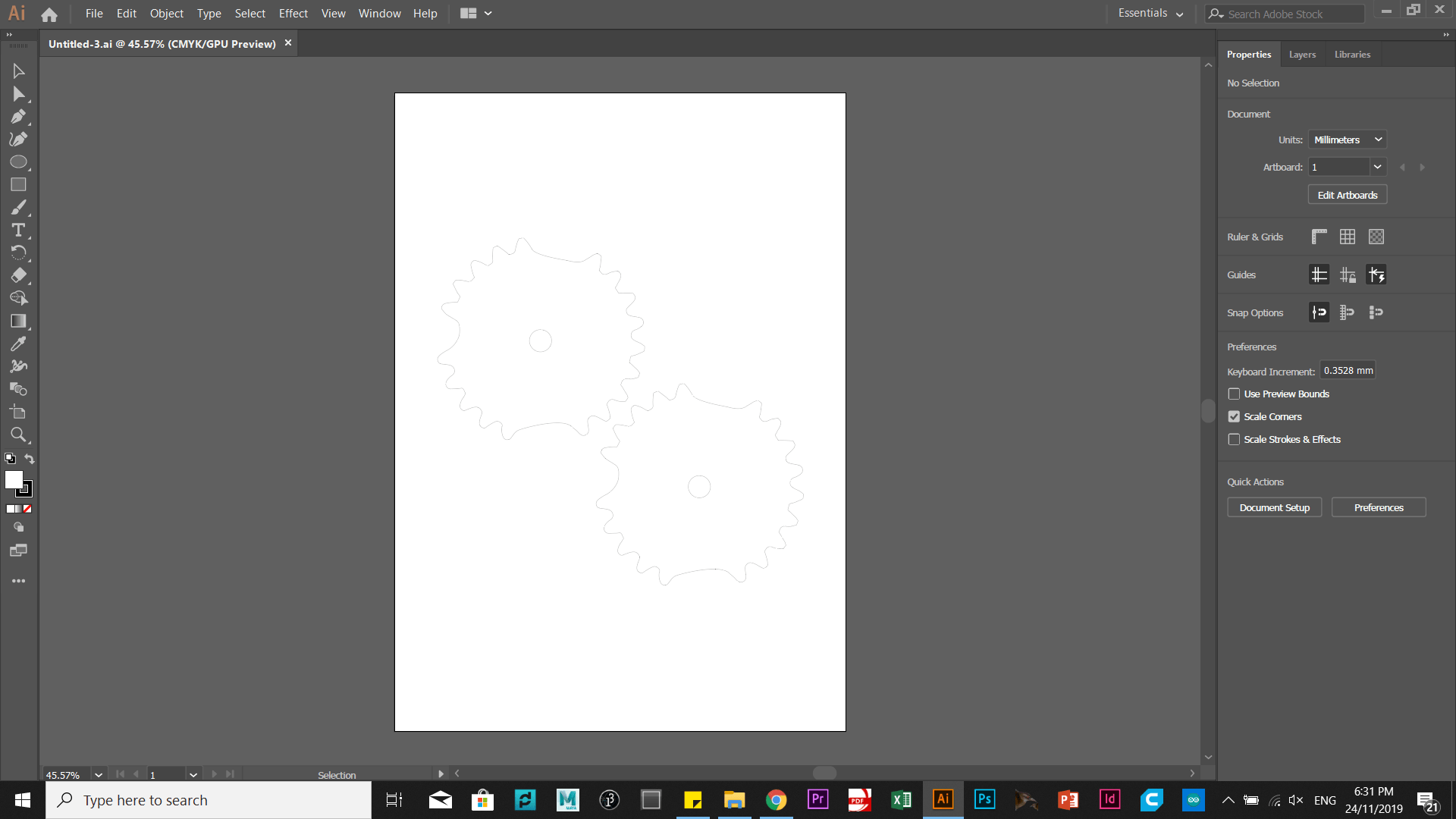
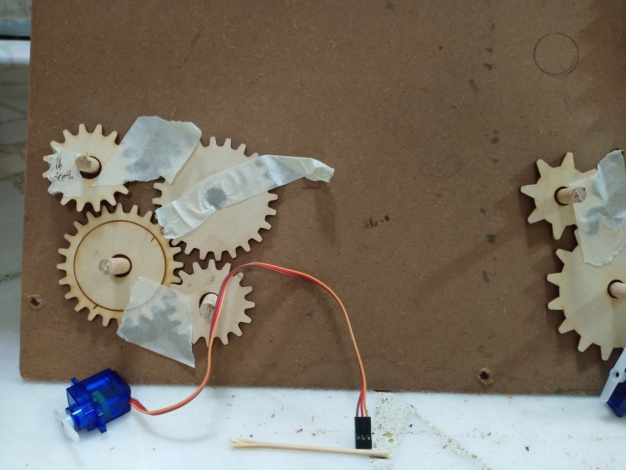

Afterwards, I put the gears cap of the gears together with the cap of the servo motor – glued them together and they would form a moving gear!
I made use of different kind of servo motors – but eventually the most responsive one was the small Sservo motor (180d). That worked well.
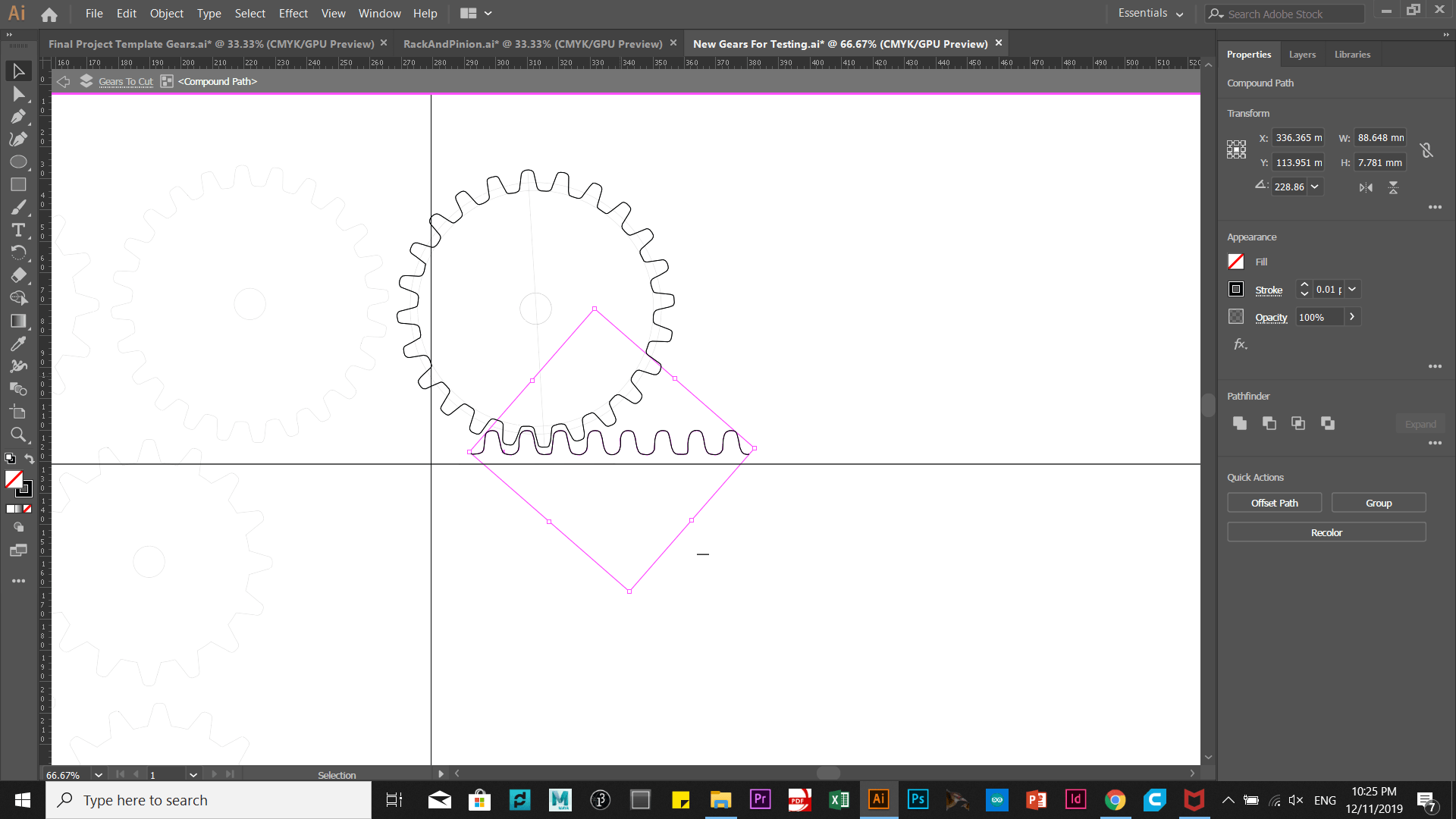
I also used rack&Pinions – which are elongated rectangular platfors that has teethr esembling the gears. It would be moved by the gears from one end to another. I was given suggestion to add something that bridges two or more families of gears together – so that there would be an interaction between them. However, because I customized the shapes of the gears and its teeth differently, it was hard for me to make another set of rack that bites well with gear. Fortunately, I made a rack that bites well and moves with the gear ( Type C Gear).
code used
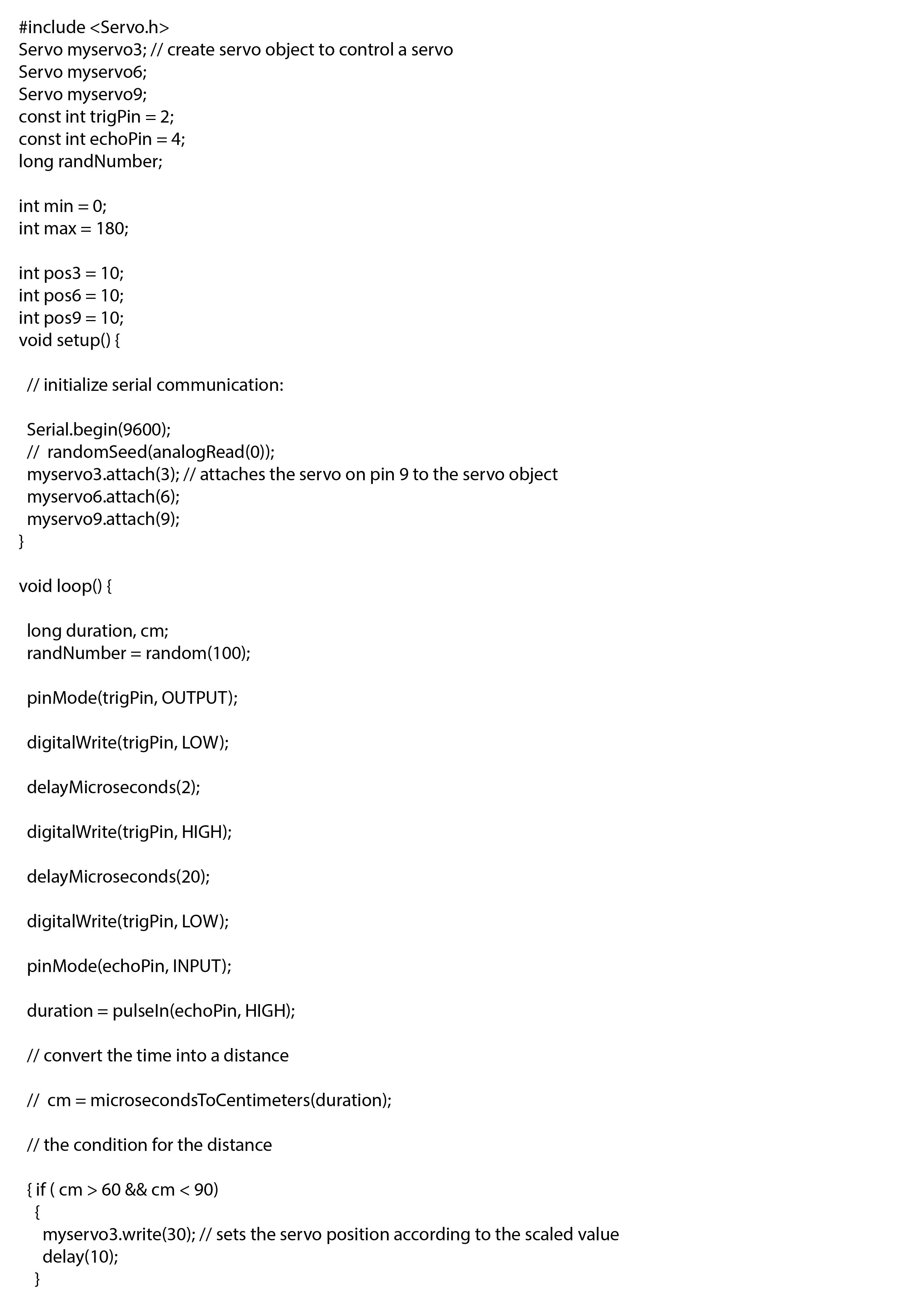
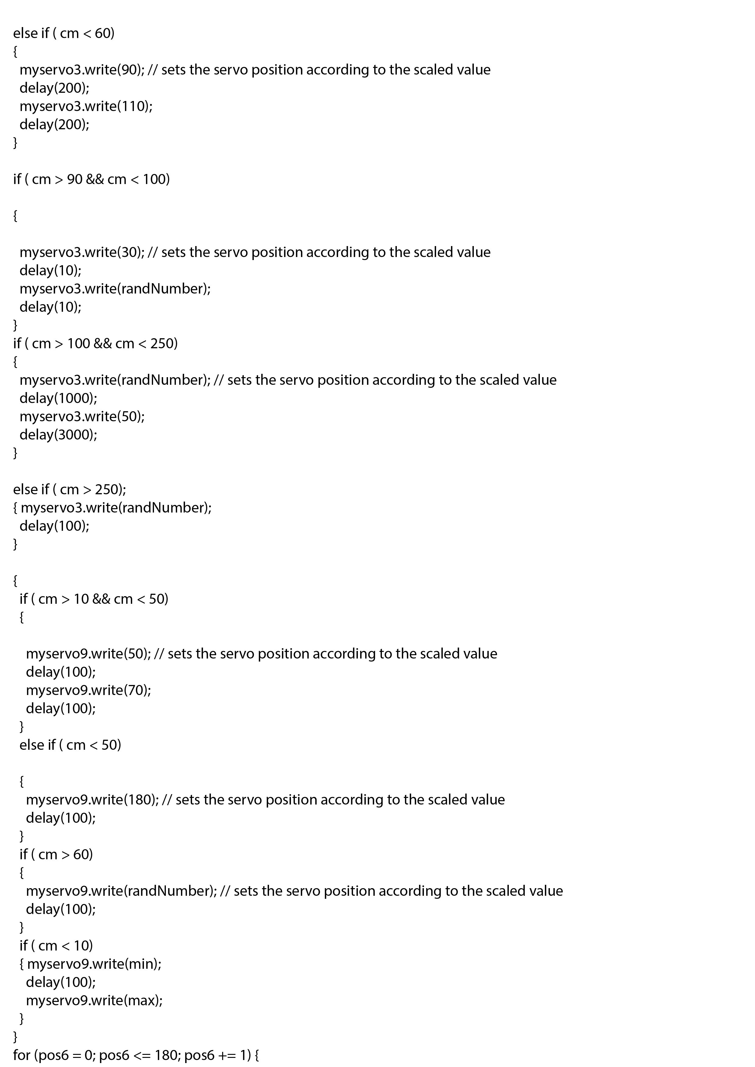
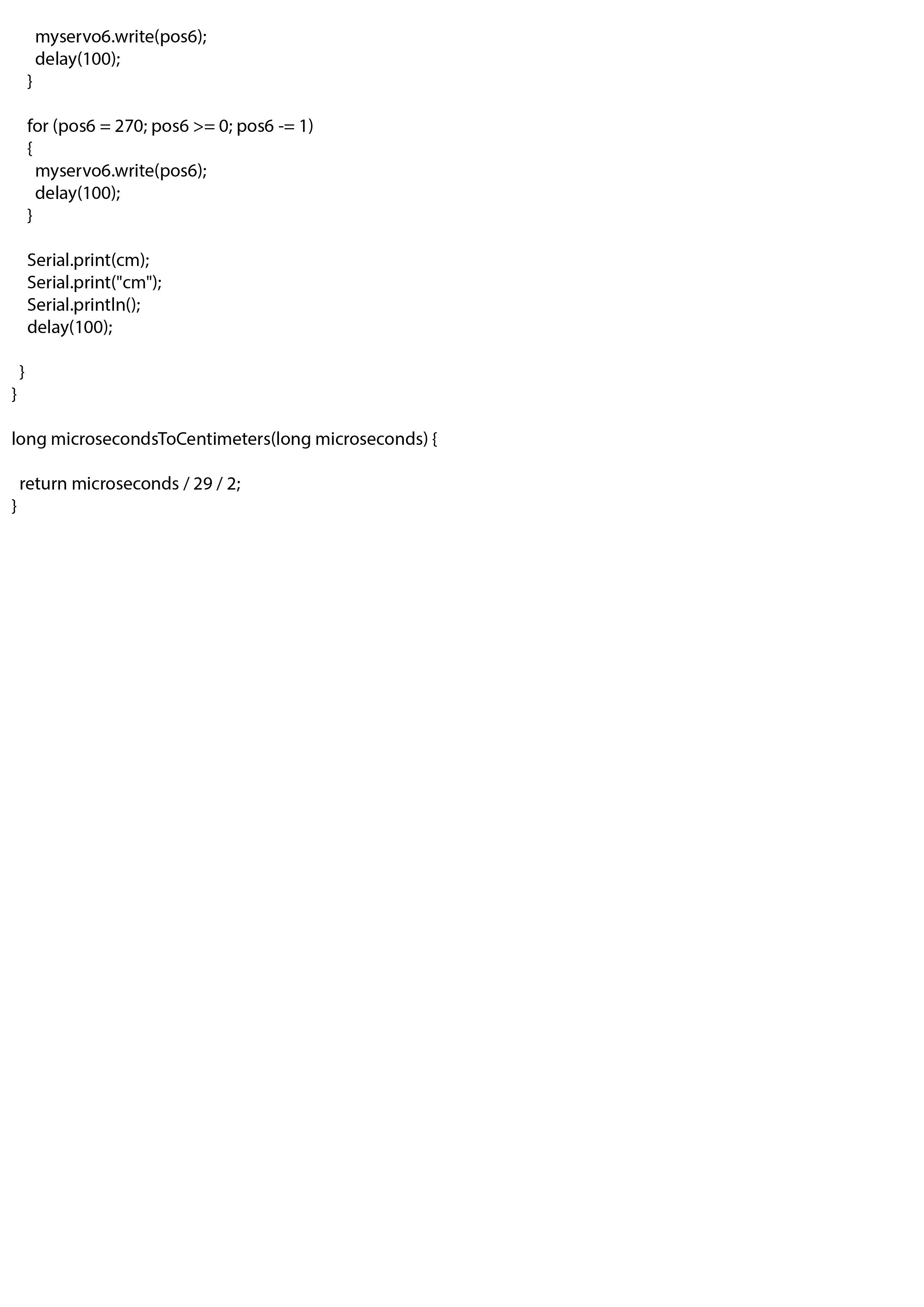
I had several files of code to experiment the movement of servos. By playing around with the code made me realize how it takes a lot of power for the three servos to play at the same time ( even though they are all bracketed together).
https://www.instructables.com/id/Controlling-a-Servo-With-Ultrasonic-Sensor-Signal-/
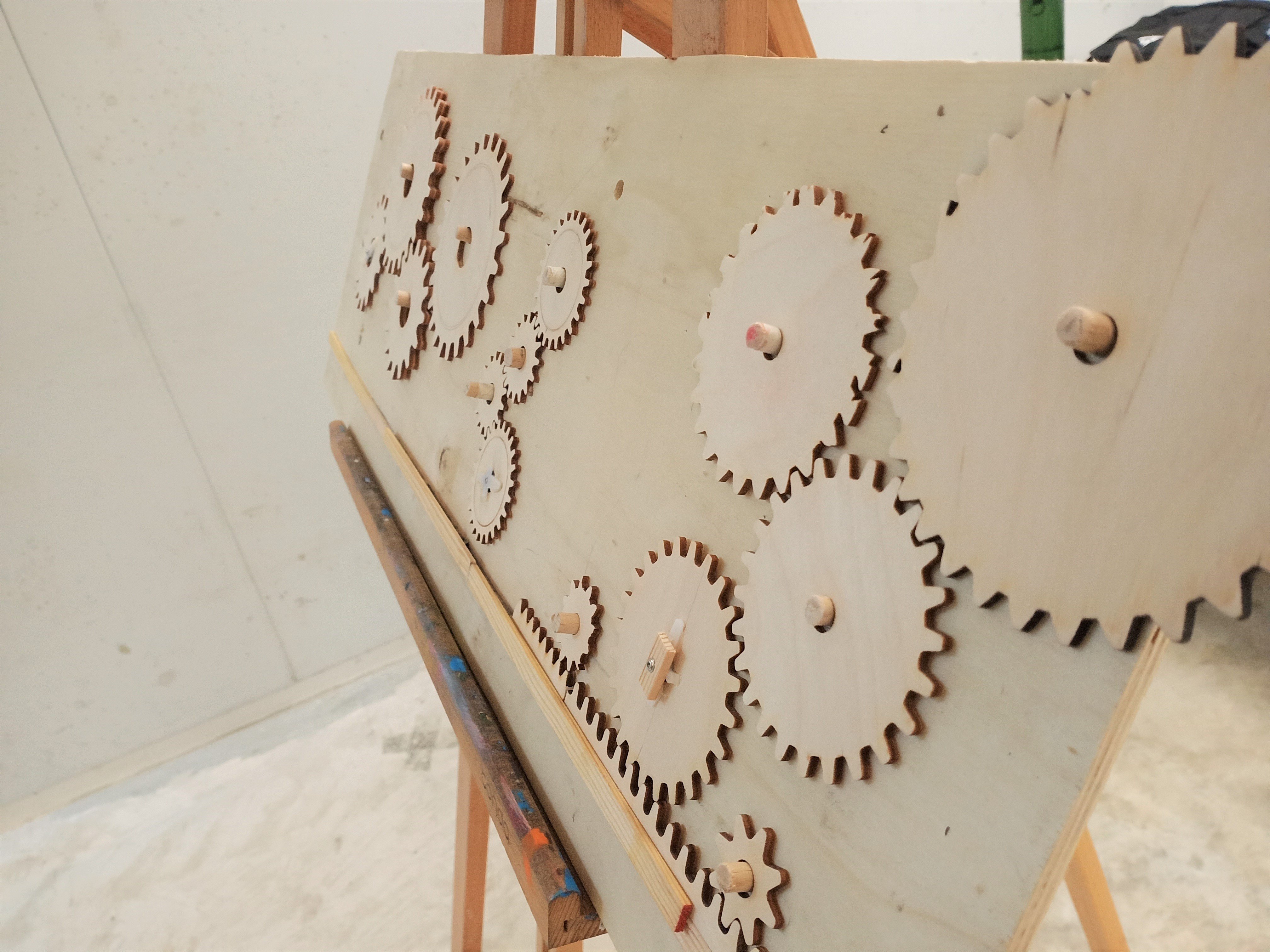
refinements made
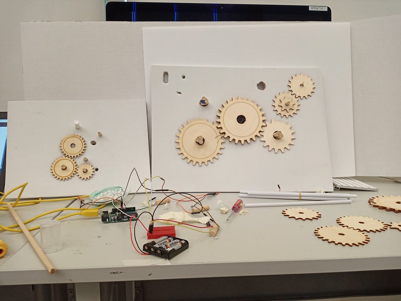
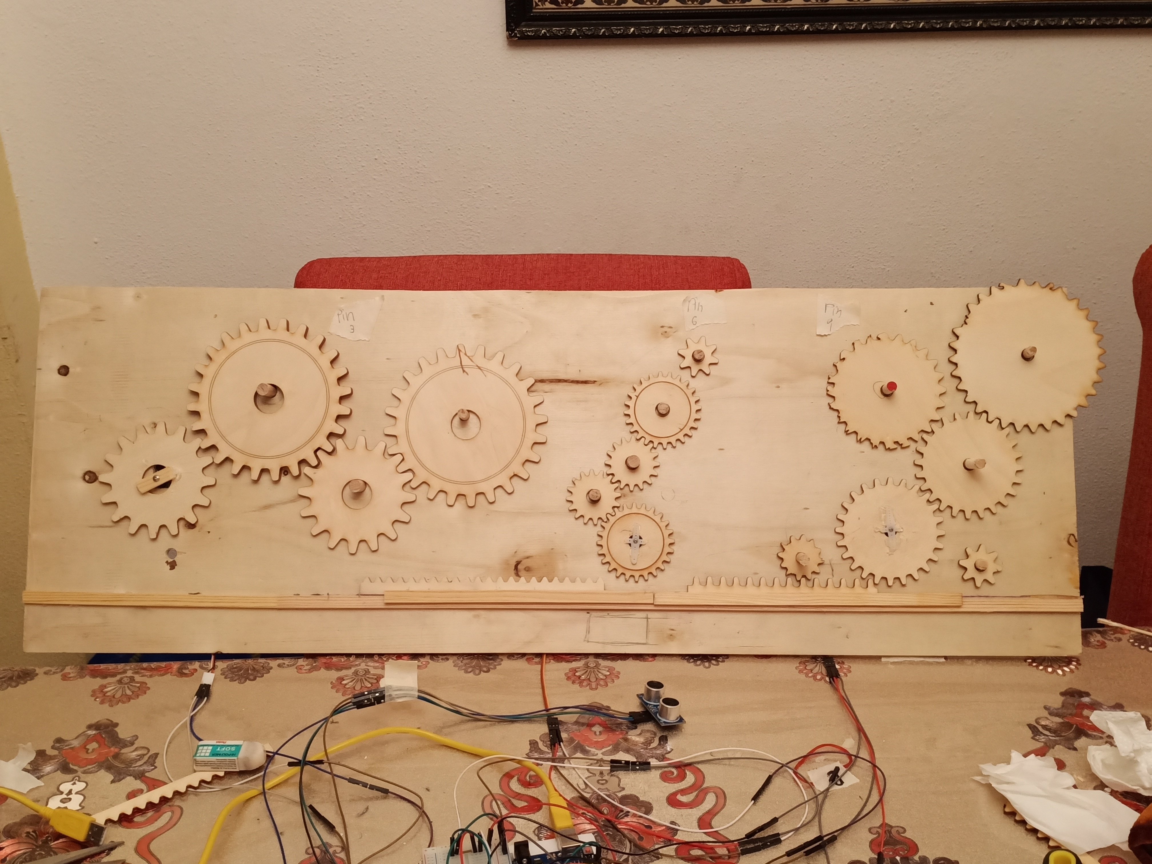
The gears managed to move together – that was an accomplishment. I was very glad that the teeth gears bit each other making the movement quite seamless. The distance sensor could receive data of person standing close/further away from the gears, and this is shown through the various speeds or type of movement the gears made. Only Type A gears (left) moved depending on the sensor. The other two did not. This was not possible to make all three move simply based on one sensor – however with the help of Zifeng it was actually possible to do so by wiring it differently.
TYPE A (servo3.attach) – This is directly connected to the ultrasonic sensor, so this family of gears react to a person’s presence near the installation. Random function are used at distance of more than 60cm
TYPE B (servo6.attach) – This servo is not connected to ultrasonic sensor, so it moves according to the speed and delay stated above.
TYPE C (servo9attach) – This servo is not connected to ultrasonic sensor, so it moves according to the speed and delay stated above.
final


feedback post-presentation
- Backdrop for the plywood holding gears could be of a different colour – in order to bring out the gears, focused attention on gears (aesthetics)
- Use of easel – which is normally used to hold paintings, changed the way we see gears on plywood when it is used to support them – especially with difference in movement of object
- With 3 “families” of gears, it would be better if one family affect the negihbouring one, followed by the next one – with the ultrasonic as the trigger
- deliberate probabilities – where there are 3 outcomes in terms of type of movement, however use a random function to get 1/3 probabilty of that outcome