Visual Pulse ( Process + Final )

Objective

Using a pulse sensor, this visual pulse is used to take in data of a person’s pulse rate, something normally felt and unseen. With the use of servos, the frequency of data produced of each person’s pulse rate affects the movement of objects beneath the fabric. This follows a rhythmic pattern that is shown through this device. A visualization of our pulse rate is an alternative to our palpitations that we feel by hand.

PROCESS 

Initially, the main objective was to put the servo motor in a container filled with water, so that the movement of the cap would allow the water to create ripples. These ripples would form some pattern that is aligned to one’s pulse rate, and that I thought was an interesting concept I could explore.

(insert video of container of water with servo movement for proof of experiment)

As much as I almost got into making a servo move the water in a container, it also had its risks too. And one included – servo being spoilt and not being functional anymore. I made a hole at the bottom of the container, so that this would allow the cap to be placed on top.  I sealed the holes with some “Epoxy” – like a waterproof glue. It almost worked until I realize that the cap needed some room to move because it is directly attached to the servo.

ALTERNATIVEs THAT WORKED

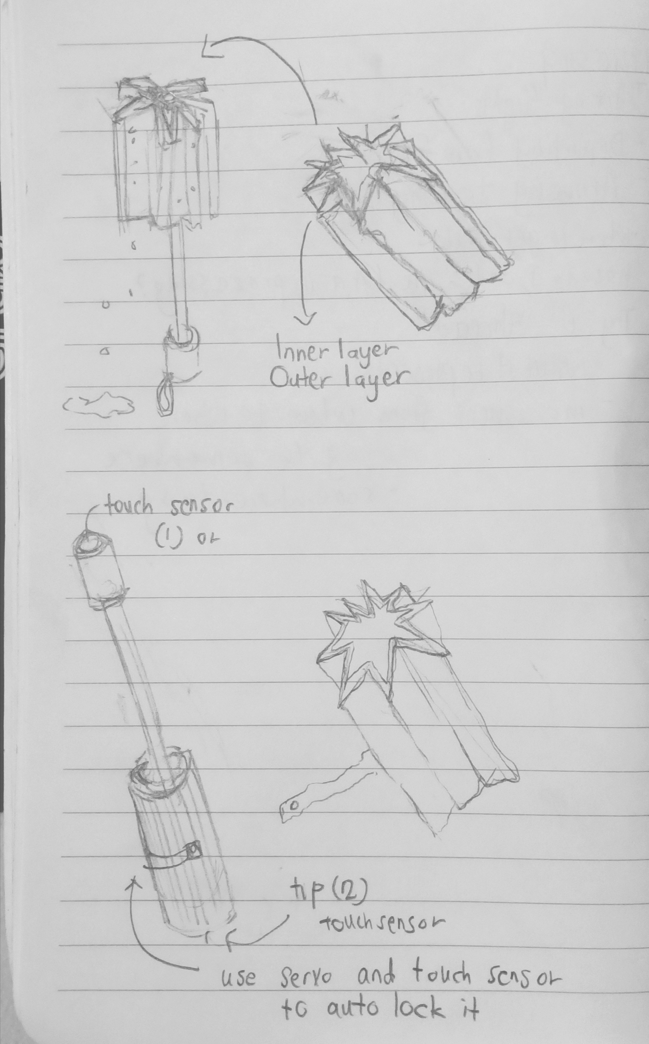
On the other hand, my professor suggested I used an object that is shaped in a way where the height would dip-and-fall continuously ( with help of servo). I made several shapes of that, that would work and this is the outcome.

After that, I was also given suggestion to add a fabric that is stretchable, so that this would cover the movement and allow it to move nicely. I lasercut a box and made some holes at the bottom so that it would be possibly for me to sow the some parts of the fabric to the bottom of the box. This would give the shape of the object when it moves. Additionally, I thought of just creating a lid that has the stretch fabric over it, so that this would be easy for me to work around object in the box with removing fabric that I thought had to be sewn.

Finally, after I was done with putting the pieces together, here is the outcome. I am quite satisfied with the way it turned out. The code worked and it really did sensed someone’s pulse rate when they touch the pulse sensor. At the same time,  I think there is definitely room for improvement!

Things that worked

  • pulse rate follows accurate to a person’s palpitations
  • movement of the objects inside he box
  • the rod planted in the servo cap managed to move – sand the insides of rod to make it fit into the servo cap, which would allow the rod to move in proper direction

Things TO better IMPROVE

  1.  Hide electronics with same cloth
  2. Code the pulse sensor such that device remains still when not in use, the pulse rate will activate when it is being touched – takes away use of pulse sensor
  3. Construction of device can be better visually – tilt it, so that its shape resembles pulse rate out put
  4. Measurements of the clear acrylic box
  5. Be  economical with buying materials and constructing it properly – get measurements accurate first before putting them together


Pitch Proposal For Final Project

Pitch Proposal

  1. Umbrella cover with dual materials that absorbs water from rain as soon as cover senses material of the umbrella and able to dry it quickly.
  2. Use an electronic eraser that follows the movement of waving hang gestures to wipe off dirt from a whiteboard.
  3. Belt tighter made to control how tight belt bucks is over waist without touching it.

Overview of the project

  1. To create an umbrella cover with dual material that absorbs water from umbrella so that you can store it immediately without anything else getting wet, efficient way with after-use of umbrella
  2. To ease use of magnet-attached duster by adding electronics and sensors to ease movement of duster on whiteboard – easy erasing
  3. ???

Few sentences / Image

  1. A wet-umbrella cover that is water absorbent and doesn’t wet the surrounding objects once the umbrella is slot into holder
  1. An automated white board eraser that follows hand gestures to wipe dust off board / An Automated eraser that moves according to user-controlled object attached to it
  2. ??

Context / Rationale

  1. Immediate dry after using small umbrella for easy storage in bag. Normally after using it after use from rain, the wetness keeps one from not storing it immediately inside the bag, inconvenient to store in holder because it is not water absorbent, holder usually misplaced or lost ( there are exceptions :P)  By adding dual material with inner layer – a material that absorbs water, and outer layer – a material that holds shape of umbrella & strong handgrip.
  2.  This reduce effort needed by people, usually educators using the duster to wipe of dirt from board. Reduces effort, reduces unnecessary time wastage, allows user to control direction of duster for erasing

Why is this relevant?

  1. This is relevant in a wet weather where there is little to no space for an umbrella to be dried off immediately, unless you  are at a given space for a long period of time. By introducing an umbrella cover, it removes the hassle of finding a space to leave it out in the open, as likelihood of drying takes longer ( esp in wet weather), and also possibility of misplacement, forgetfulness and theft.
  2. Allows another user to wipe off dirt with little effort; simply make wiping hand gestures that allows movement of duster on board. This is relevant in a period where unnecessary time need not be wasted on activities such as erasing the board

Solution to a problem? Design Object? Experience ?

  1. Solution to a problem – reduces time and effort, likelihood of misplacement and theft
  2. Solution to the problem – reduces time and effort in a time-structured setting such as teaching in a classroom,  discussion in a board room where whiteboard is used as a medium


Aesthetic/Artistic realm -or- Design realm

  1. Assuming the mini umbrella has 8 flaps, the holder can slot 8 flaps fittingly, dual material with inner and outer layera. Inner material – thin foam, spongy material, any material water absorbentb. Outer Material – rough but thin that can be easily gripped by hands, flexible so it is wrappable before making a lockInteractive Element: ??
  2. An object that moves on its own without

Similar works, critique and differences

Inspiration sources

Interaction (describe how people will interact with it, cover many scenarios):

Metaphor / Principles

Storyboard /Mockup

Implementation

Technologies

a. Inner material – thin foam, spongy material, any material water absorbent

b. Outer Material – rough but thin that can be easily gripped by hands, flexible so it is wrappable before making a lock ( exploe biodegradable material)

Milestones with a weekly breakdown of tasks to accomplish.

Description of the first prototype.

How will you work be shown at the end of the semester?

How will you document your work? mainly the interaction?

Device of the week: IoT in Telemedicine

Internet of Things (IoT) is the idea of physical objects being able to  communicate online and interact with other objects.

.. defined the Internet of Things as “a world where physical objects are seamlessly integrated into the information network, and where the physical objects can become active participants in business processes.”

From my understanding of Telemedicine, it serves as a very efficient way of providing immediate care to people who may need medical assistance but have difficulty travelling to hospital . It allows certain groups of people, for examplem the elderly the fastest care and provide practical help that they need in case of emergency. It acts  like  “virtual hospital”. At the same time, with the use of smartphones or tablets, doctors can deliver medical assistance on-the-go by keeping a tab of the patient’s condition online.

One of the most simplest forms of Telemedicine allows a patient to consult doctor online without being physically present – this can be done through use of Webcam or Skype.

A more advanced version is the use wearable technology that tracks the blood pressure or heart rate of an elderly person that is attached to him/her at all time. This allows information to be transferred to medical professions in hospitals in real time. With the datas of rate of blood pressure or heart allows viewers to keep close eye on someone without being physically present with each other.

IMAGES & VIDEOS: 

PROS:

Close monitoring of patients even when doctor is away from patient, this is because of the apps ability to keep tracck record of each patient’s condition. This includes,measurement of data vital to patient’s . As such, this allows doctors to keep close eye of any signs that requires immediate medical attention. Allows doctors to make more accurate analysis of patients’ without even needing to visit patients with machines attached to them.

Time and cost efficient – travel costs significantly reduced because both patient can consult doctor through by appearing through communication outlet such as SKYPE with use of WIFI

CONS:

Requires strong WIFI signal to get ease of communication – without this, difficult to secure consultation, aid needed – this would be difficult for isolated areas where wifi signals are weak or non existent or unaffordable

Telemedicine does not affect travelling required to get medicine/ medical assistance/nurse needed to improve patient’s health; remains inconvenient for those difficulty travelling

Breakdown in internet may result in data loss – that is vital for record keeping for patient’s health and doctor’s analysis

SUGGESTIONS FOR ALTERNATE USE

I think this device can be further improved when another one is made, that gives an alarm to neighbouring family members residing in  same household but different space. This would not only alert doctor with said data with calling emergency unit, but it also alerts close caretakers. It could be like an immediate alarm bell or a vibration on his/her phone to signal that he/she assist in giving physical aid to patient.

Assignment 2 Interactive Devices


Reference:

or this assignment, the devices that I used were servo motors and ultrasonic sensors. The distance sensor would allow movement of the servo motor. When a person moves closer to sensor, it would detect some movement and allow it to move. I was a bit uncertain with the whole concept of my idea, but my idea was to initially show that once a person goes close to a sensor, the movement would stop, and the clothes would go to its original position. This fabric is supposed to move on its own when servo moves, I thought that adding string attached to the main fabric would allow other fabrics to move. IT worked, but the movement was too fast. The feedback that I got was the “Delay” function was the main issue since I wanted the servo to move slowly. Perhaps I could improve by making sure the servo was coded well.

It was my first try with the sewing method, so since Galina taught us that a little bit, I had the privilege of getting my own sewing machine from home. With some fabrics I took from Product design room, I used that for sampling and incorporated certain floral designs in my project. I am happy to know that I picked up sewing skills pretty fast.


Code for Assignment 2


// Include the Servo library

#include <Servo.h>

#include <Stepper.h>

const int trigPin = 6;

const int echoPin = 7;

int servoPin = 3;

int servoPin1 = 4;


long duration;

int distance;

int setSpeed;

Servo Servo1;


void setup() {

Serial.begin(9600); // Starts the serial communication

Servo1.attach(servoPin);

//  Servo1.attach(servoPin1);

pinMode(trigPin, OUTPUT); // Sets the trigPin as an Output

pinMode(echoPin, INPUT); // Sets the echoPin as an Input

pinMode(servoPin, OUTPUT);

}


void loop() {

{


digitalWrite(trigPin, LOW);

delayMicroseconds(10);

digitalWrite(trigPin, HIGH);

delayMicroseconds(10);

digitalWrite(trigPin, LOW);

duration = pulseIn(echoPin, HIGH);

distance = duration * 0.034 / 2;

Serial.print(“Distance: “);

Serial.println(distance);

}


if (distance <= 20) {

Servo1.attach(servoPin);

Servo1.write(130);

delay(100);

Servo1.write(180);

delay(100);

}

if (distance <= 50 && distance > 20) {

Servo1.attach(servoPin);

Servo1.write(80);

delay(100);

Servo1.write(100);

delay(100);

}


if (distance > 50 && distance <= 200) {


Servo1.attach(servoPin);

Servo1.write(150);

delay(200);

Servo1.write(130);

delay(200);

}

if (distance > 200) {

Servo1.detach();

delay(100);

}

}

Powering Addressable LED through Sensor

Devices used

  • Arduino Uno
  • Arduino IDE Software
  • USB Cable to connect Arduino to power source
  • Jumper wires
  • Addressable 5V LED Strip
  • Ultra Sonic Sensor
  • Breadboard

The idea for my device of the work is Ambi-Light – where you stick strips of LED at the back of a computer/TV for some light decoration, especially in a dim-lit setting. I spent  many hours of my weekend getting the code right, partly due to me being particularly unfamiliar and uncertain with Arduino. Eventually, after spending many hours tweaking codes, the outcome is closer to what I have expected.

In the context of a trade show, this ambi-light would be put in a backdrop of a black curtain behind laptops -which are for sale. With the sensor devices attached to it, it can detect distance of an object. This determines how the LED strip will function – where the further the visitors are from device, the more ‘flashy’ the out LED strips appear to be. This would result in an attention drawn to the product as visitors pass by the trade booths.

On the other hand, the closer the visitors are, the more it becomes “less flashy” where there is a gradual change in colours that is less distracting to visitors. This would allow visitors to feel more at ease as they look closely into the products because there is something to illuminate the product without being too distracting with colour changes.

Problems and how they were resolved

  • the problem with coding in arduino ide was understanding how the functions work, and how the order of each function was quite important too, eventually after much tweaking I got the result that I wanted
  • measuring a list of thresholds as a way to determine how the led lights would play out was important – because the rate + type of light patterns determine the outcome of my project which is to sell devices at a trade show
  • The distances measured are as follows

Final Work

In hindsight, the work  I put in was a spent on searching for the right code and tweaking it in terms of distances covered by the sensor. Soldiering was also something that I learnt along the way too, and I had many intense moments working on this project, despite it being “micro project”. That in itself also means the learning curve was quite steep for me, but it has also familiarizing myself with some things that I will use in the next upcoming projects. Soon to come.