Moss Machine Prototyping (FYP18)

A very, very Quick Catch up!
This post will just be a very brief update on the progress of each different aspects of the installation!

Firstly, let’s talk about the layout! My proposed space would be a slightly rectangular space, with content to be projected/hung/attached/displayed on all 4 walls. My drawn layout can be accessed here: FYP Diagram(edited final).

Planned Layout of each 4 walls of Installation

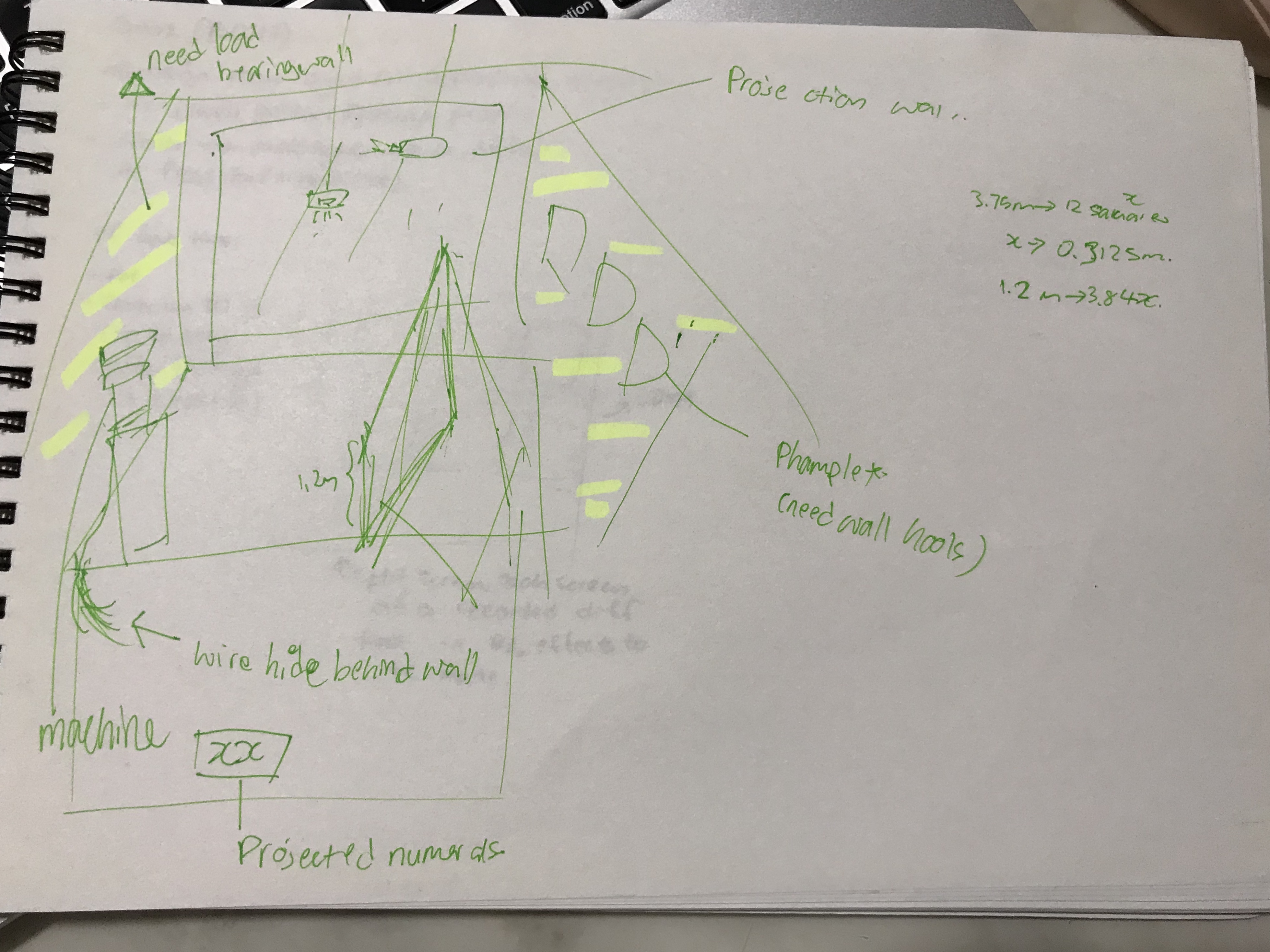
Otherwise, as seen in the above rough sketch, I would be placing:
1. x 2 projections
2. x 1 moss machine
3. Phamplets, memorabilia

More details could be seen here: Presentation Summarised

FYP Group Presentation with all Professors
Today, the IM cohort had a group presentation with all the IM professors. My presentation slides can be found here: Presentation Summarised


Moss Procurement Updates!

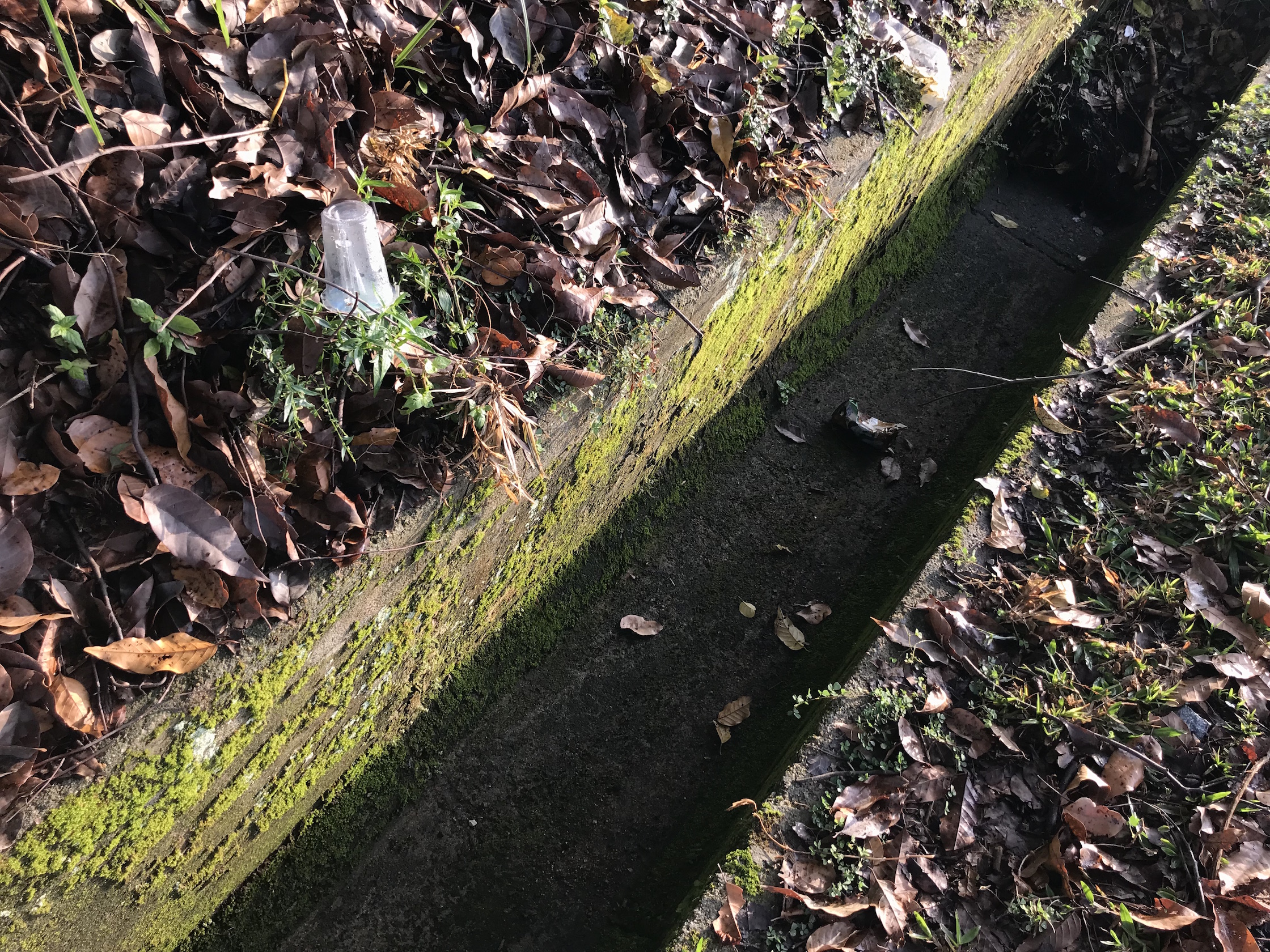
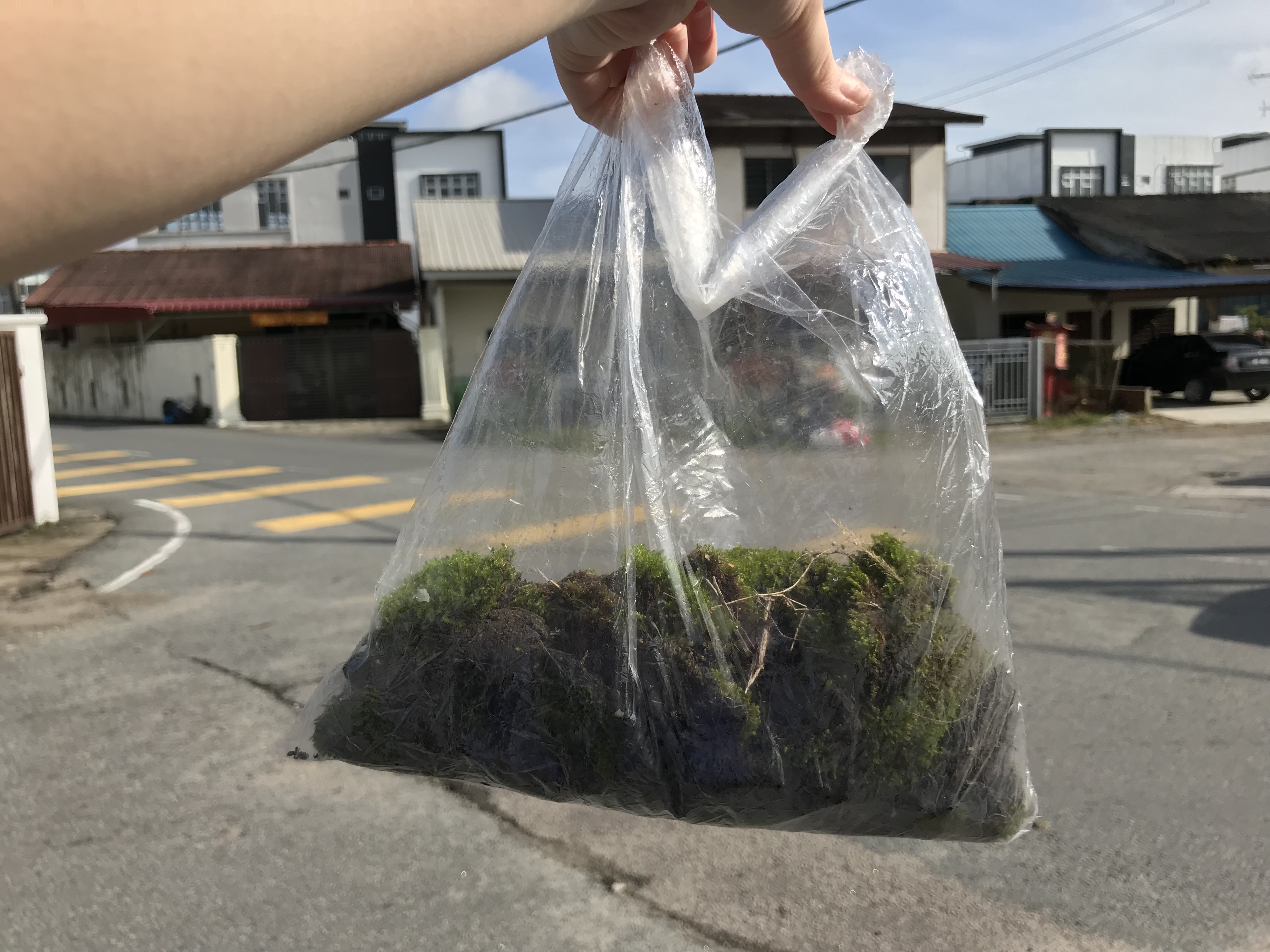
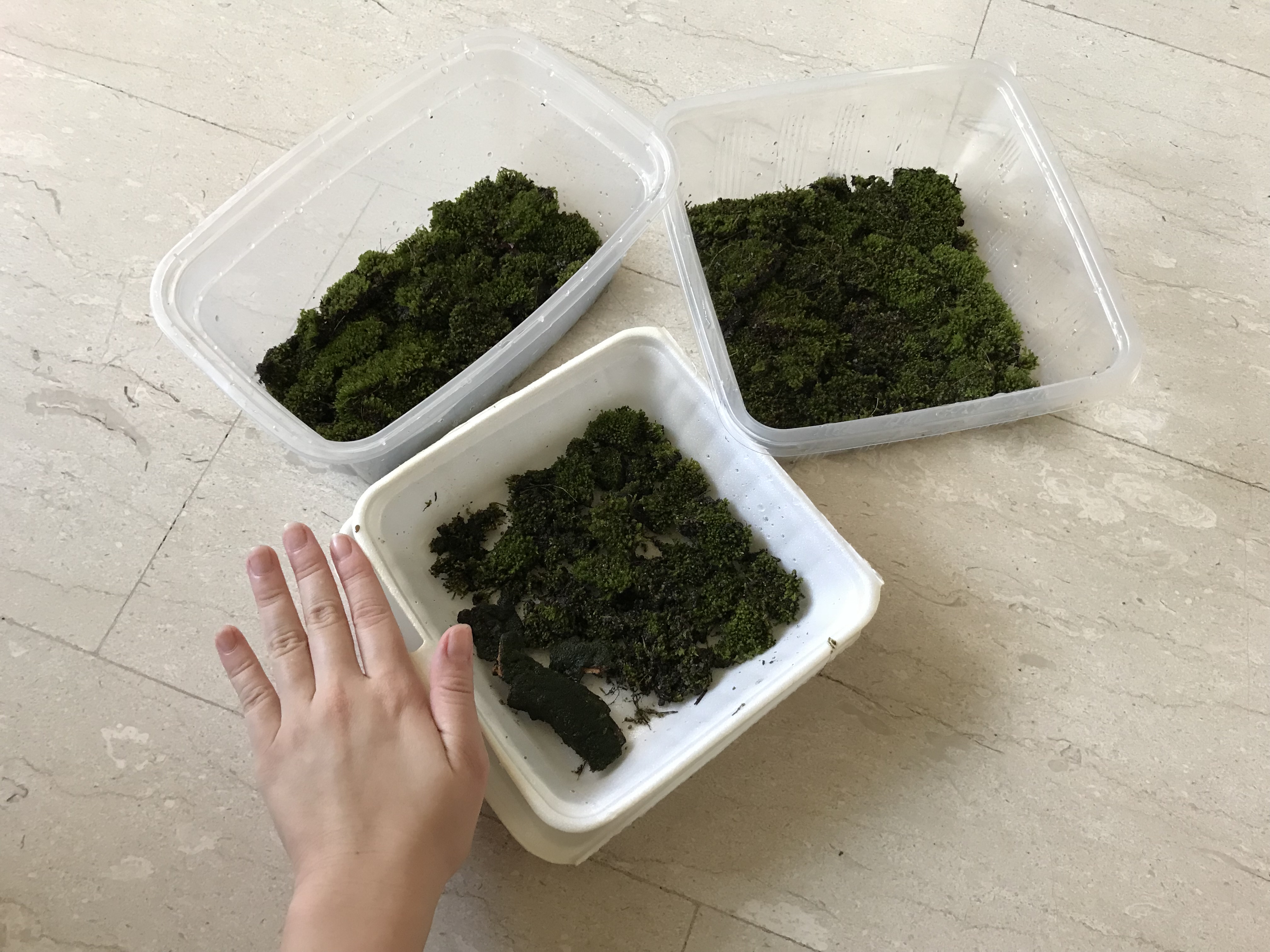
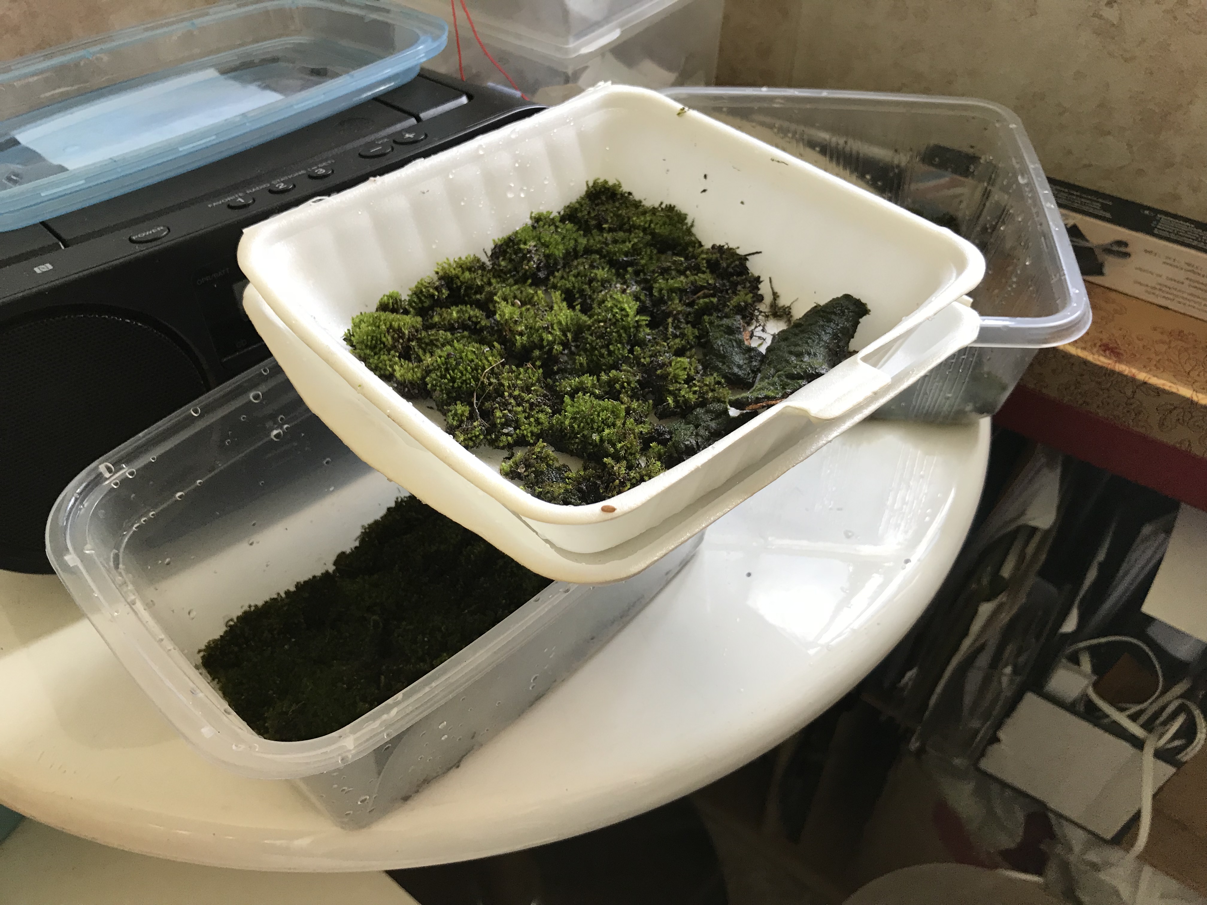
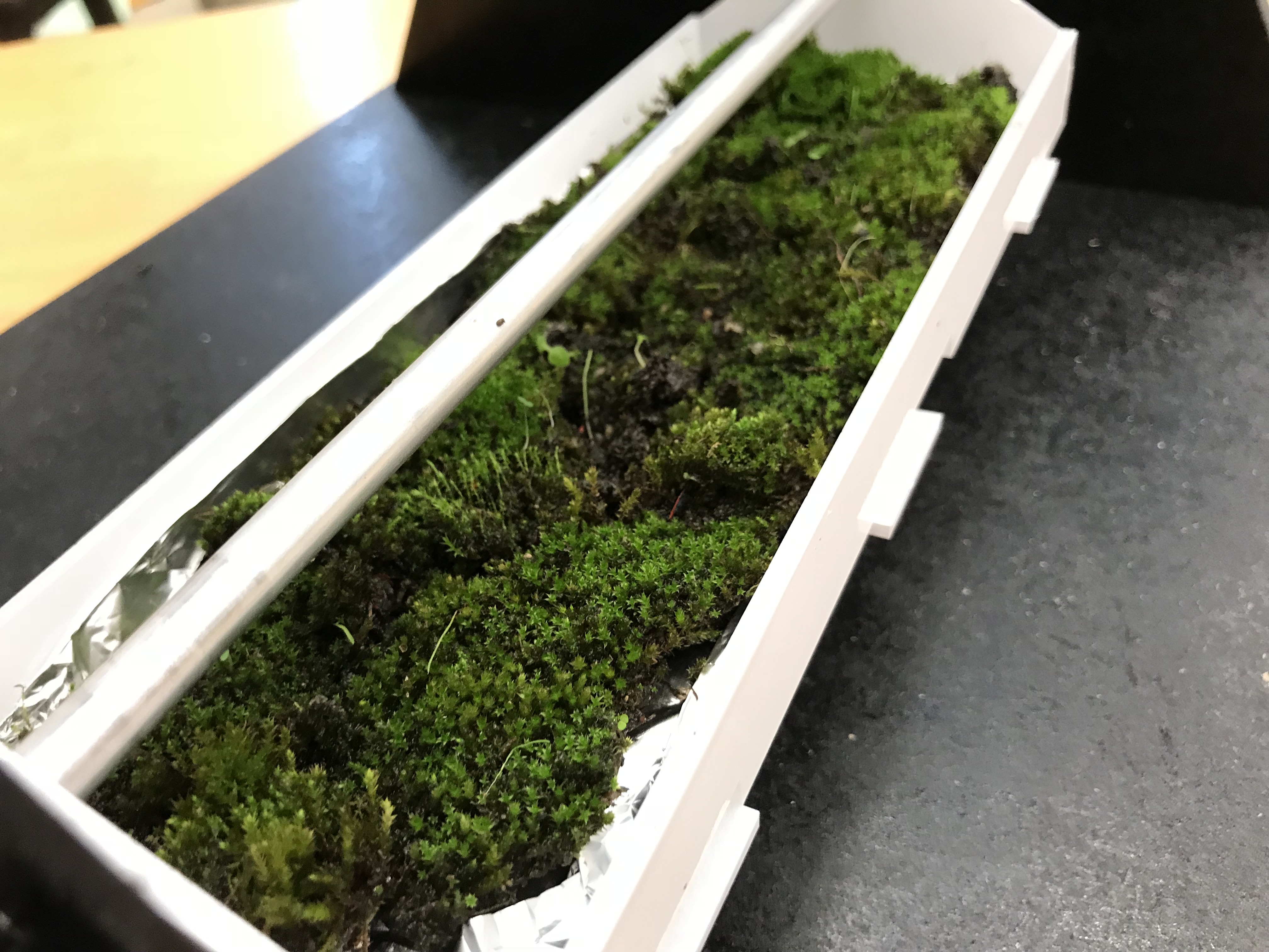
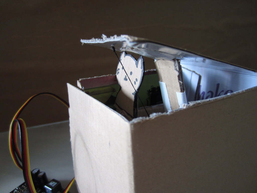
In my last post, I did mention that I would resort to buying the moss! Luckily for me, I chanced upon large quantities of this very amazing moss species on a quick trip to Malaysia which would fit the theme! However, I only managed to smuggle back enough quantities for it for the prototype itself only, and not for the final installation machine.

Close up of moss

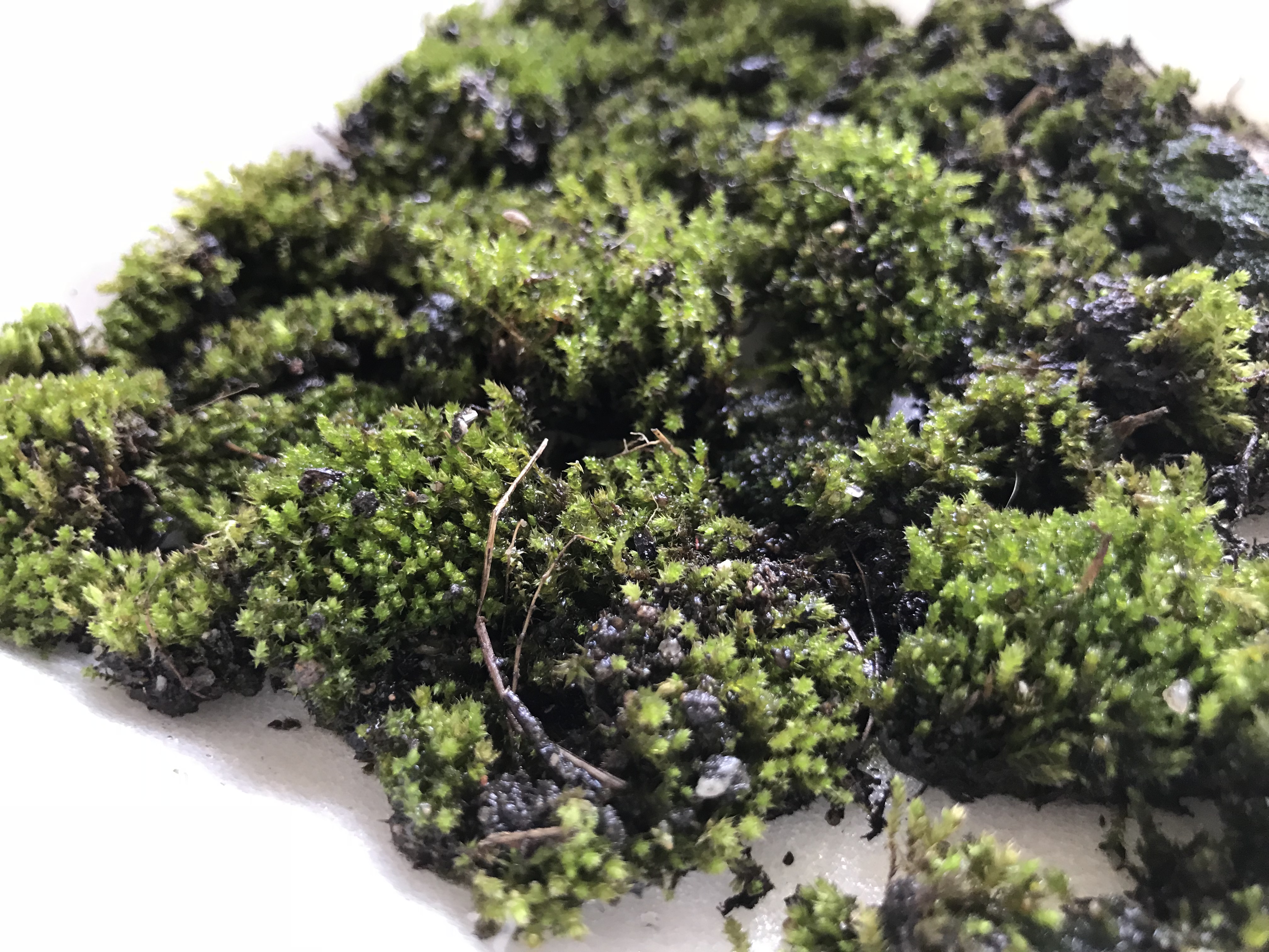
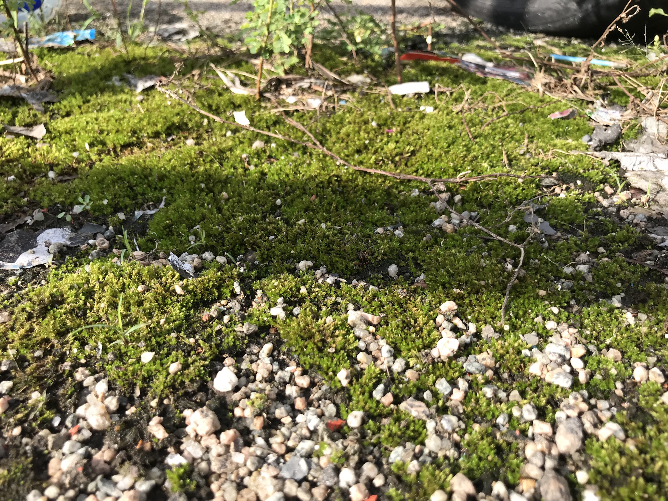
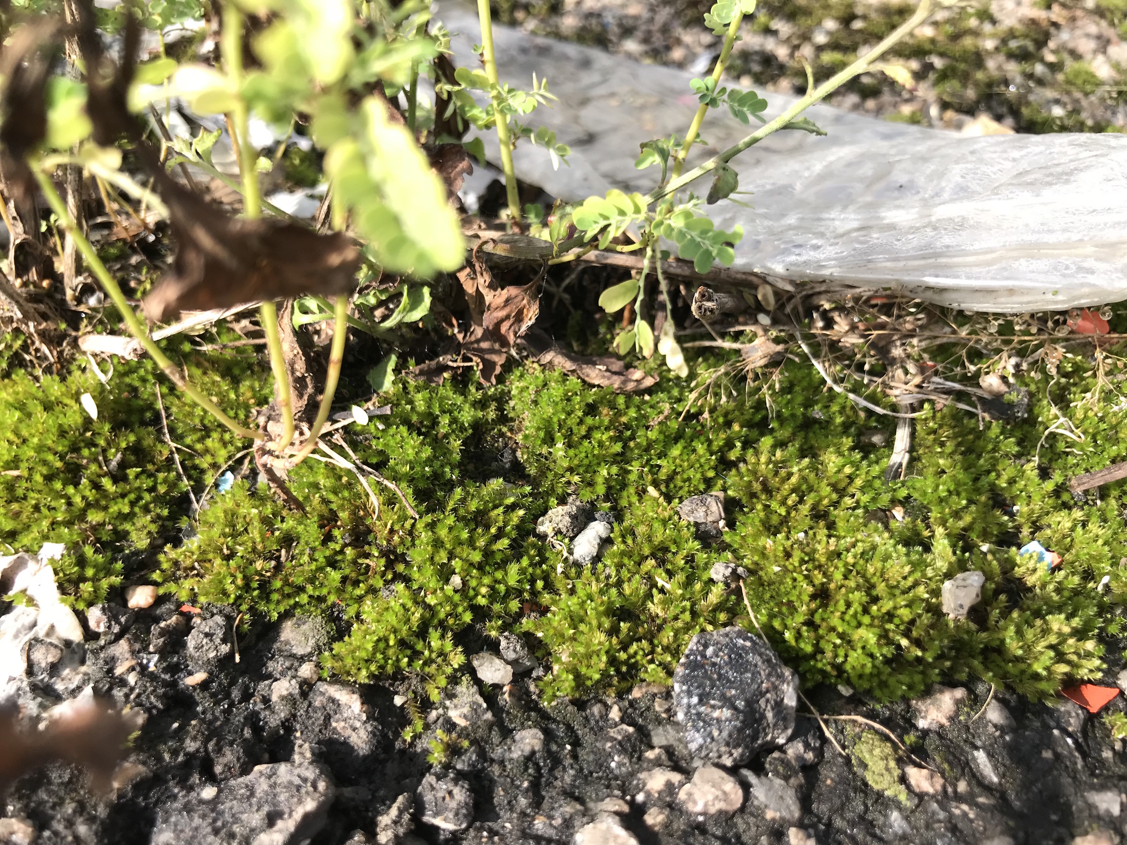
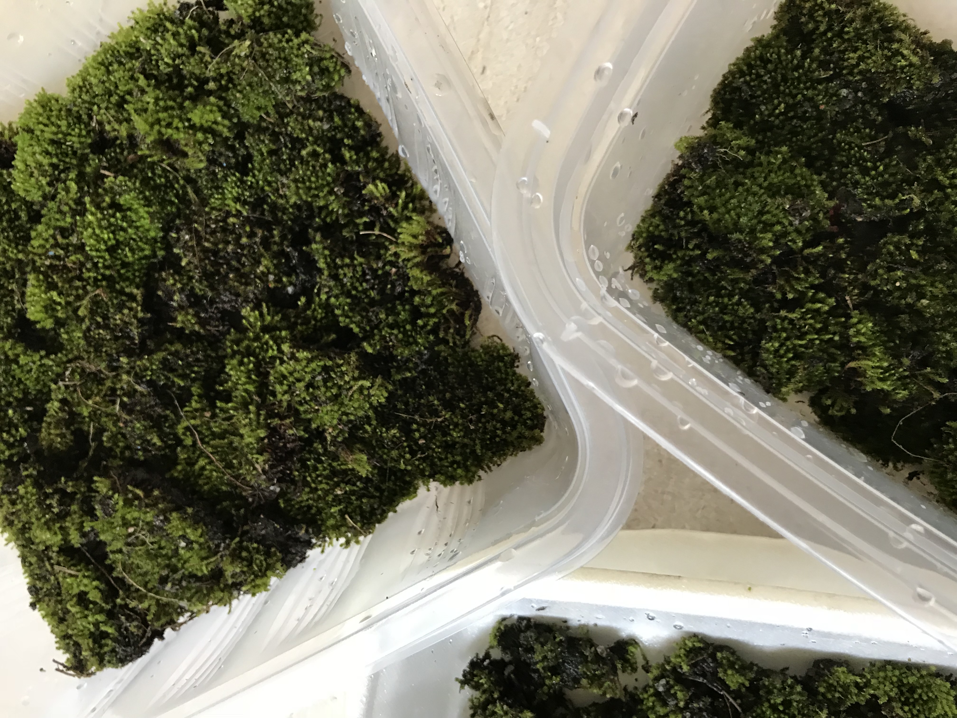
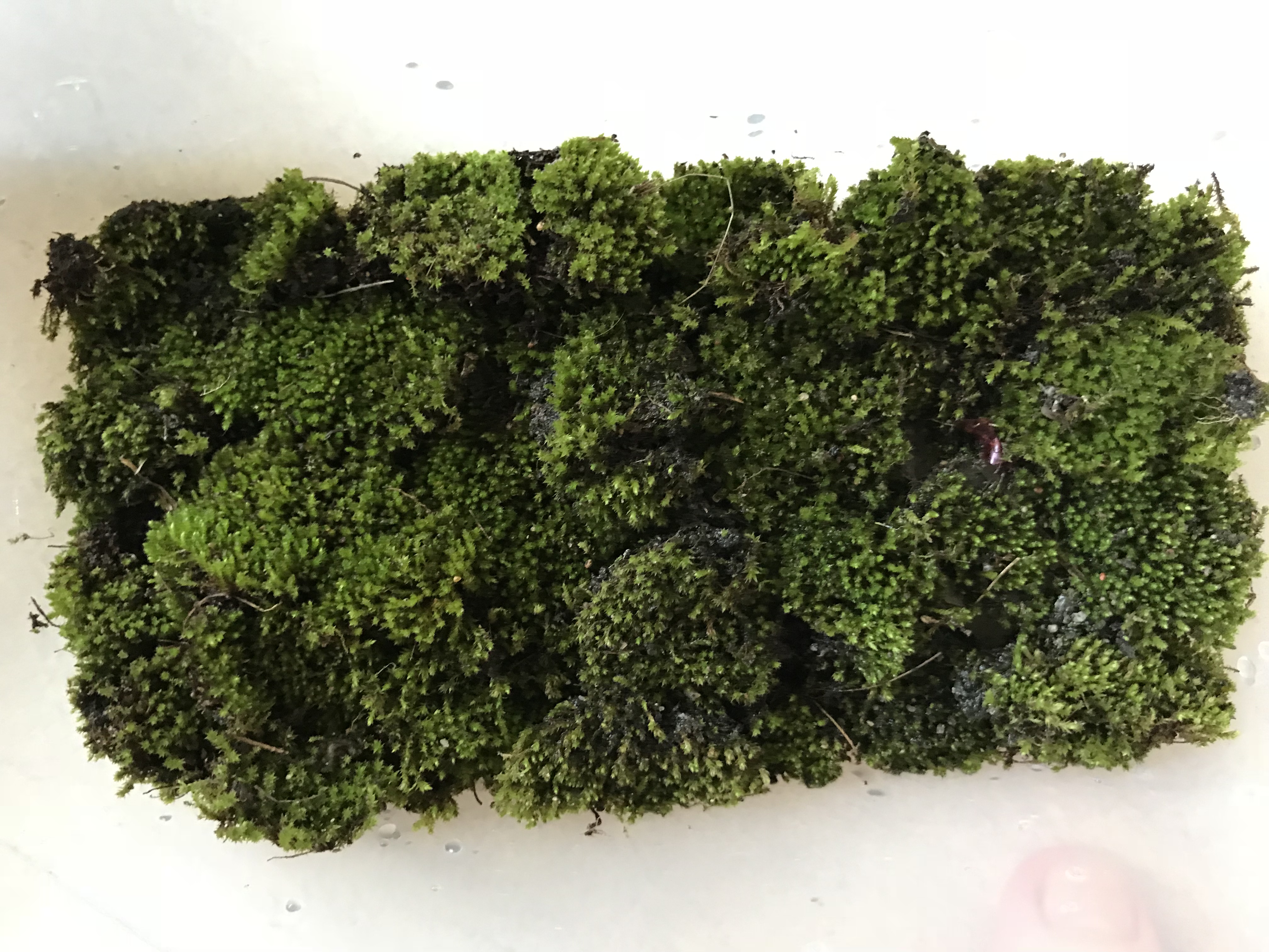
Referencing the above close up picture of the moss, I wish to draw attention to the individual stalks of each moss head – which gives additional texture and interest to the moss bed – perfect for what I envisioned.

As of now, I have a dilemma of whether to purchase commercially available Holland moss for the final machine or whether to return to Malaysia for the sole purpose of moss collection. Logistically speaking, I am also unsure if the border controls will allow me to ‘mass import’ their local flora back to Singapore.

But for this final prototype, I have decided to affix it with this particular species of moss.
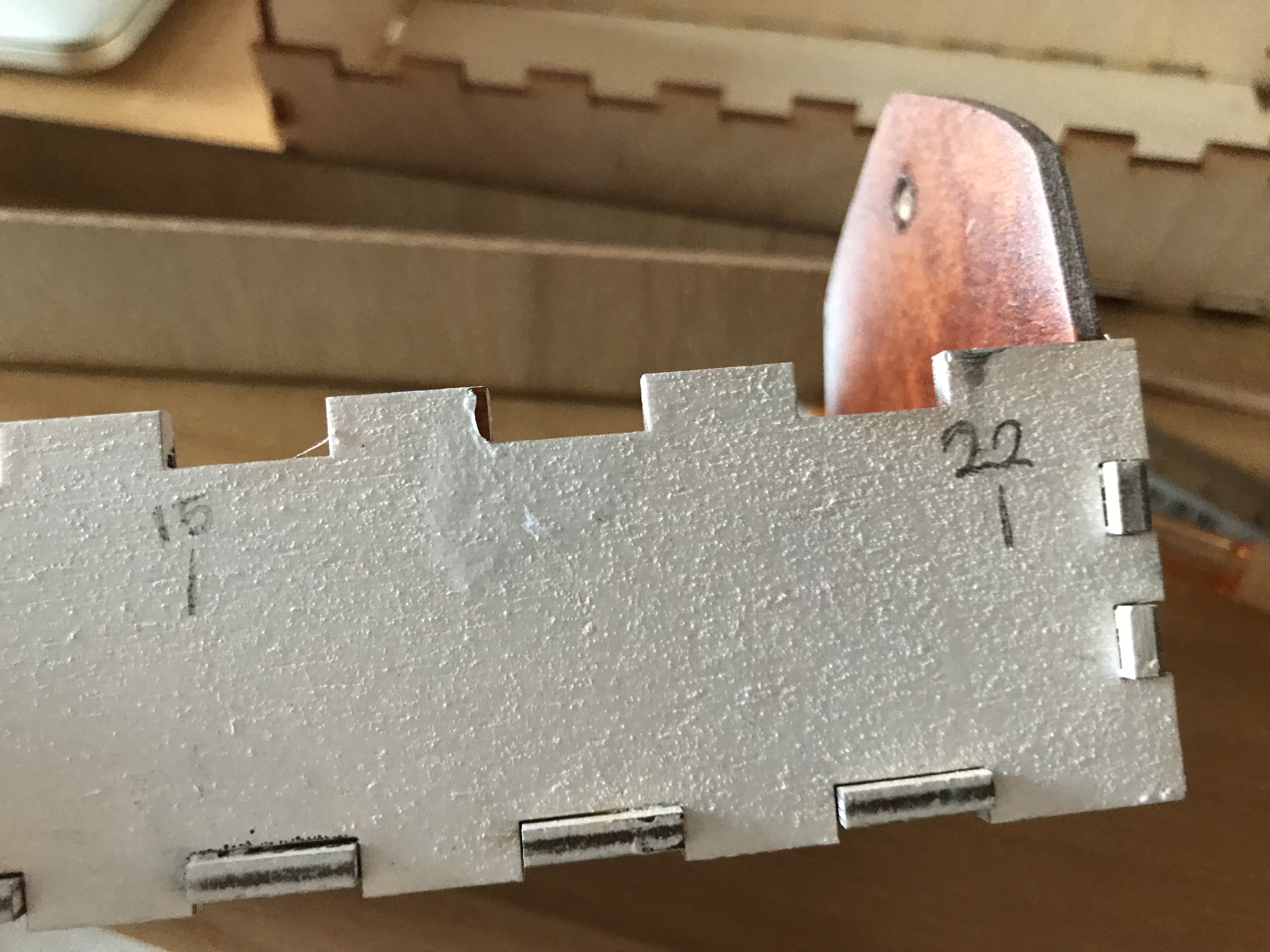
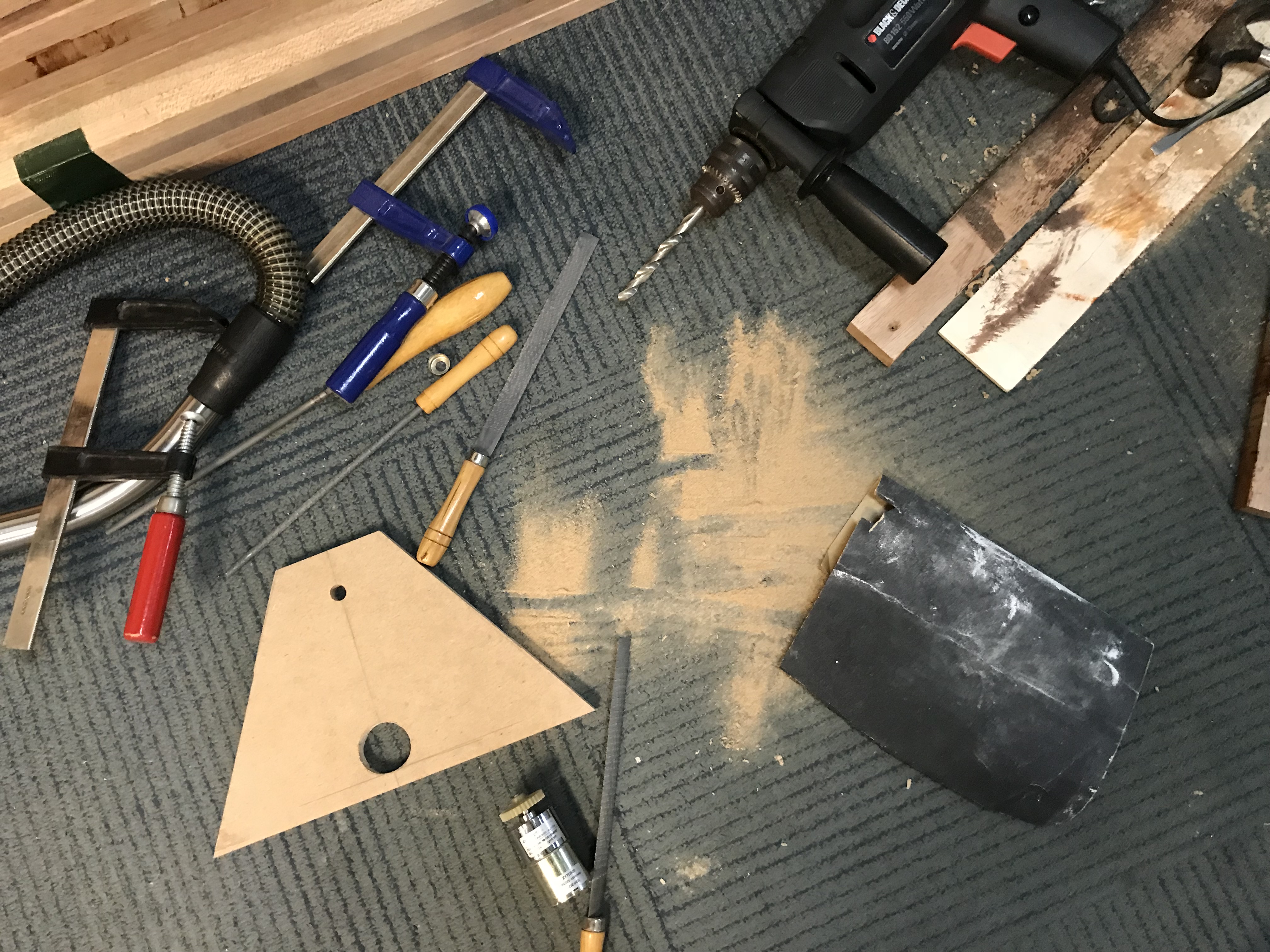
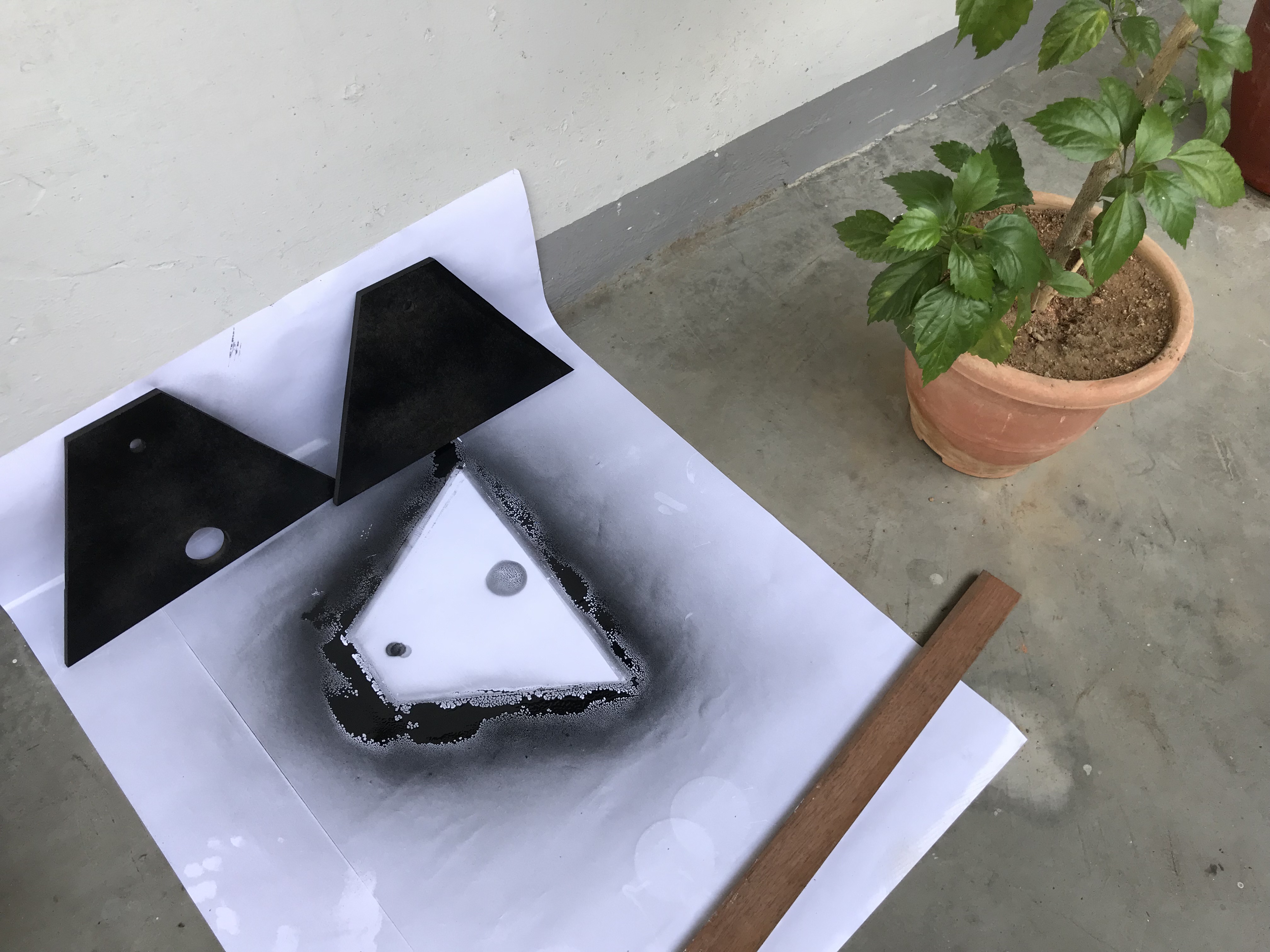
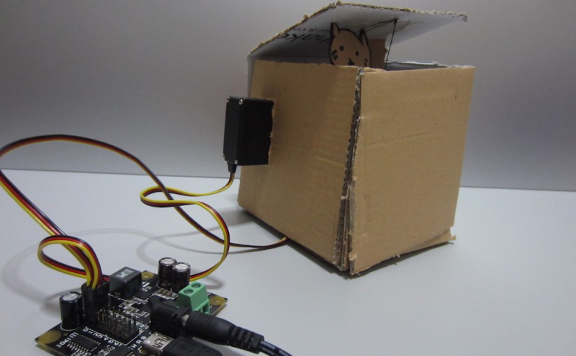
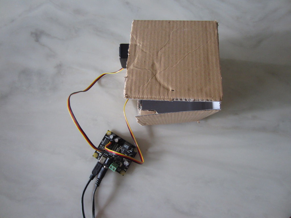
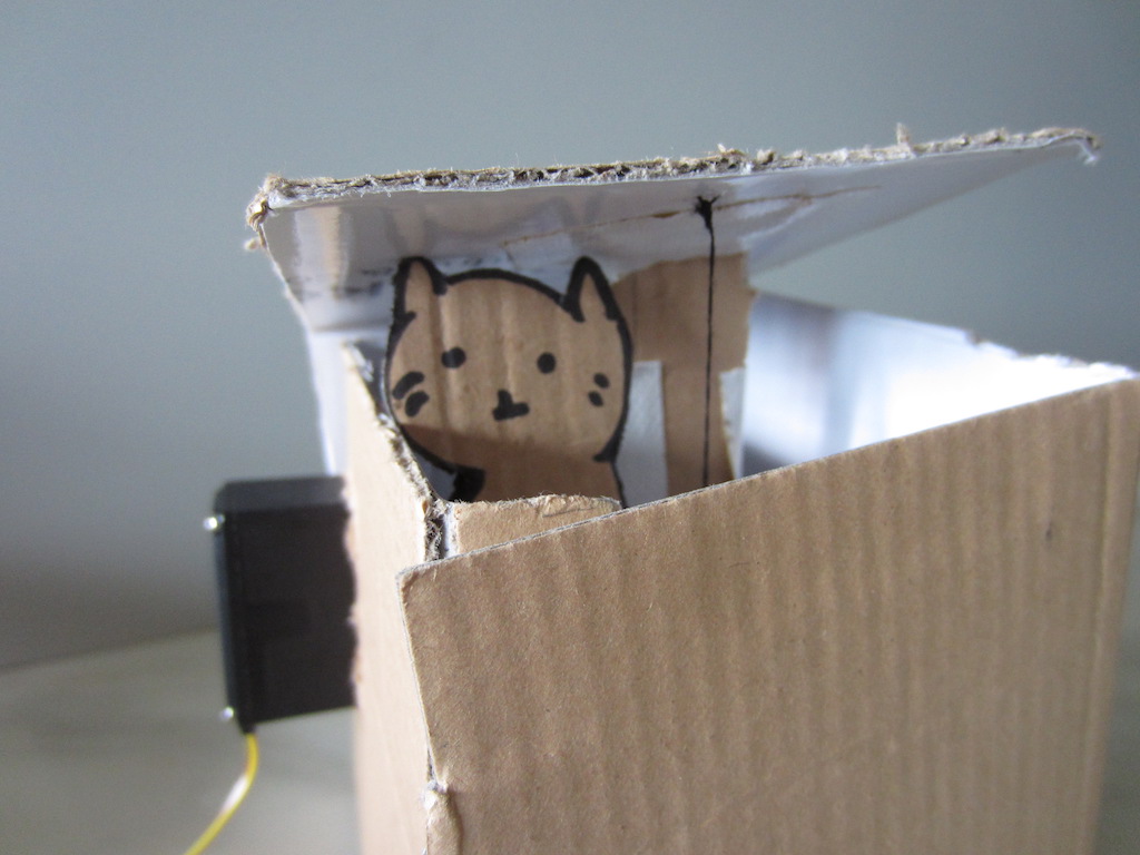
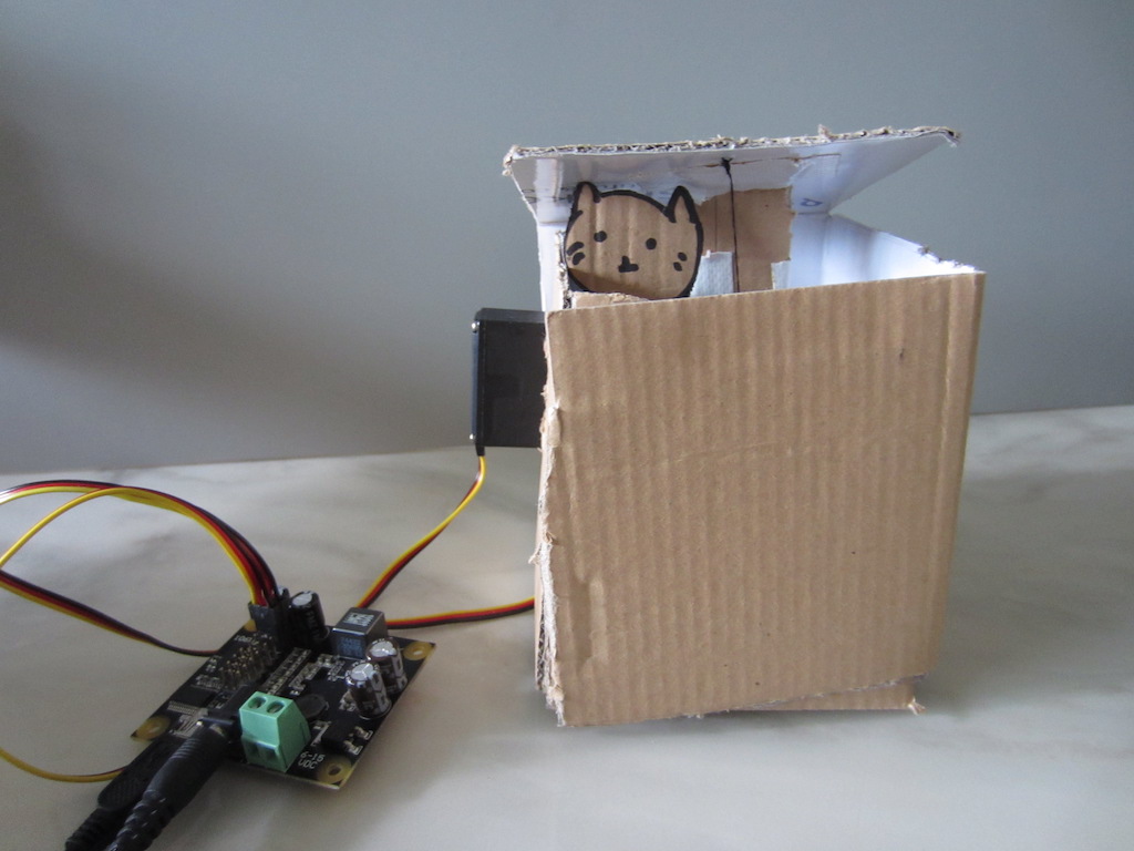
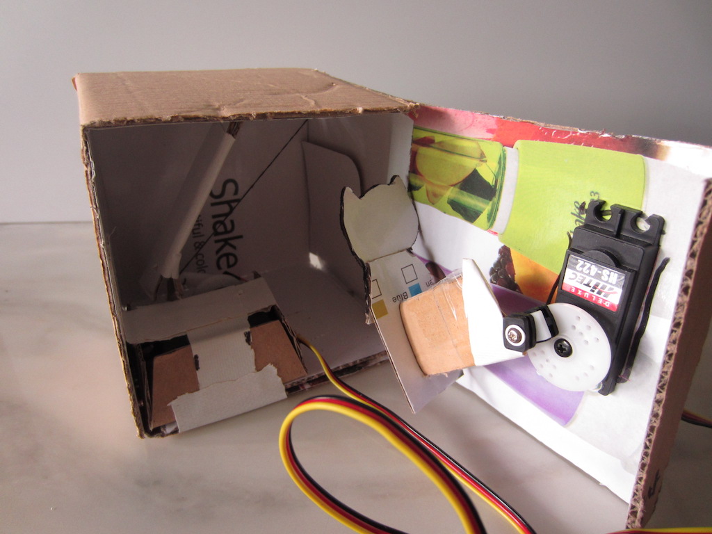

Prototyping

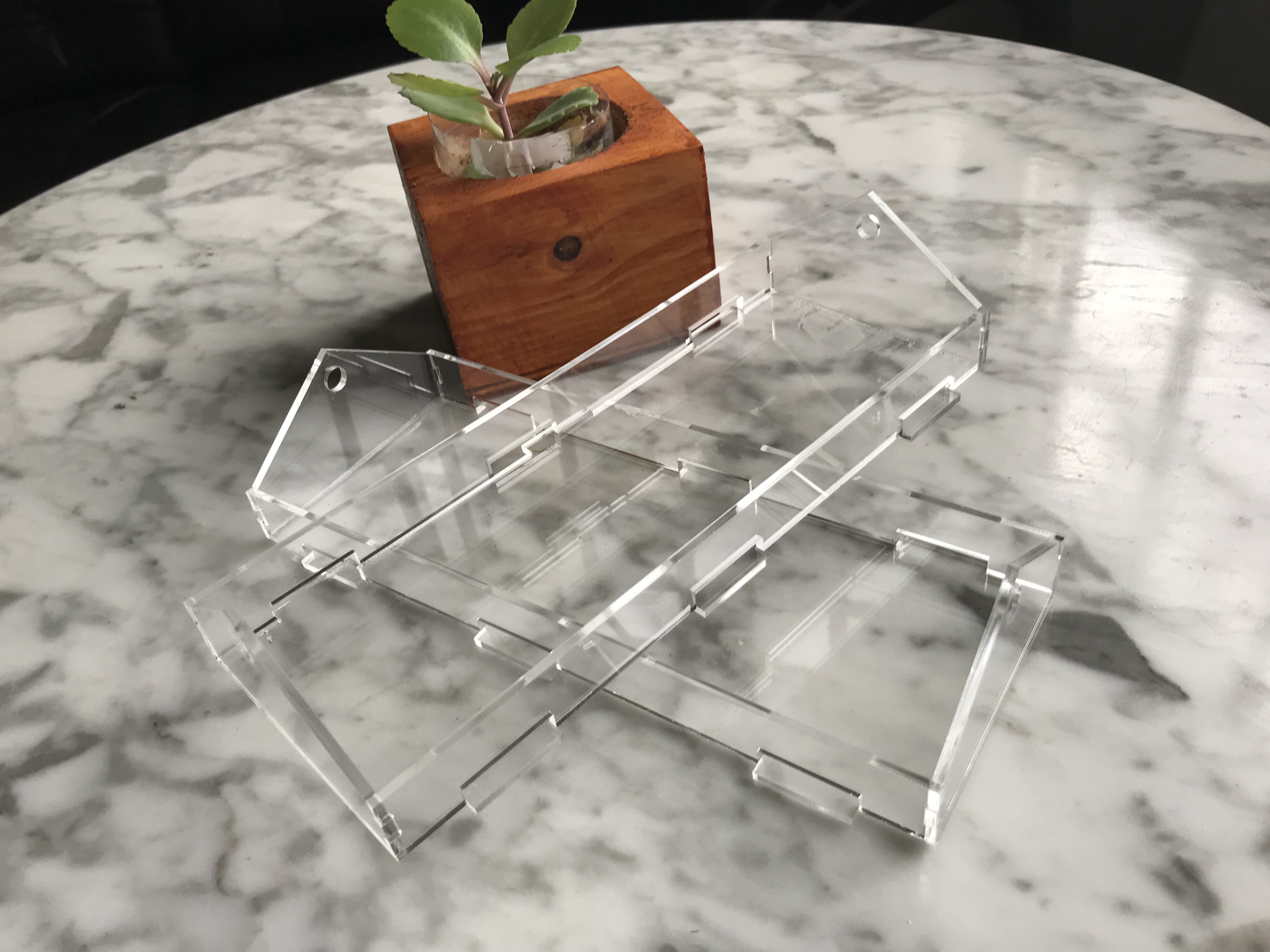
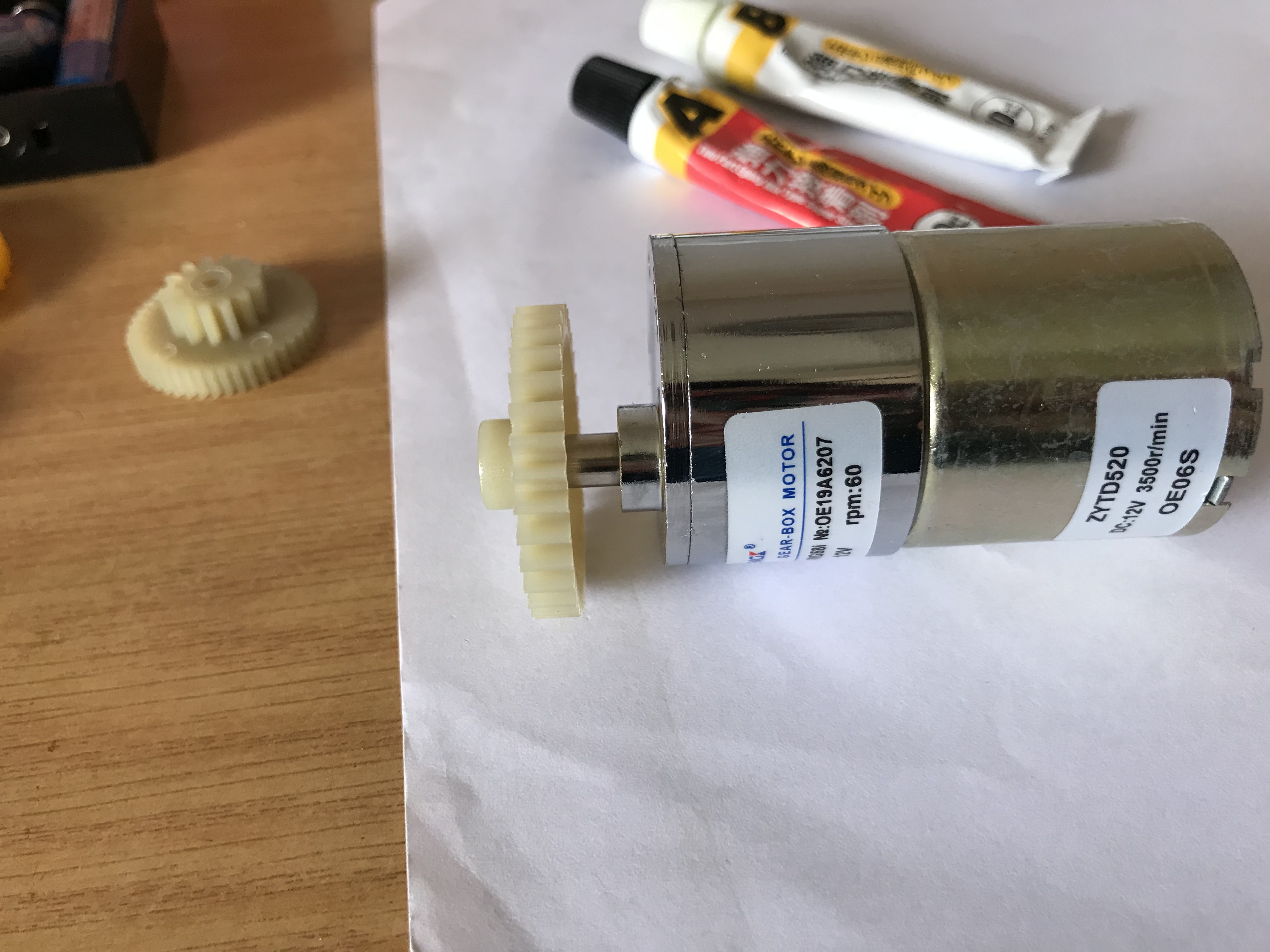
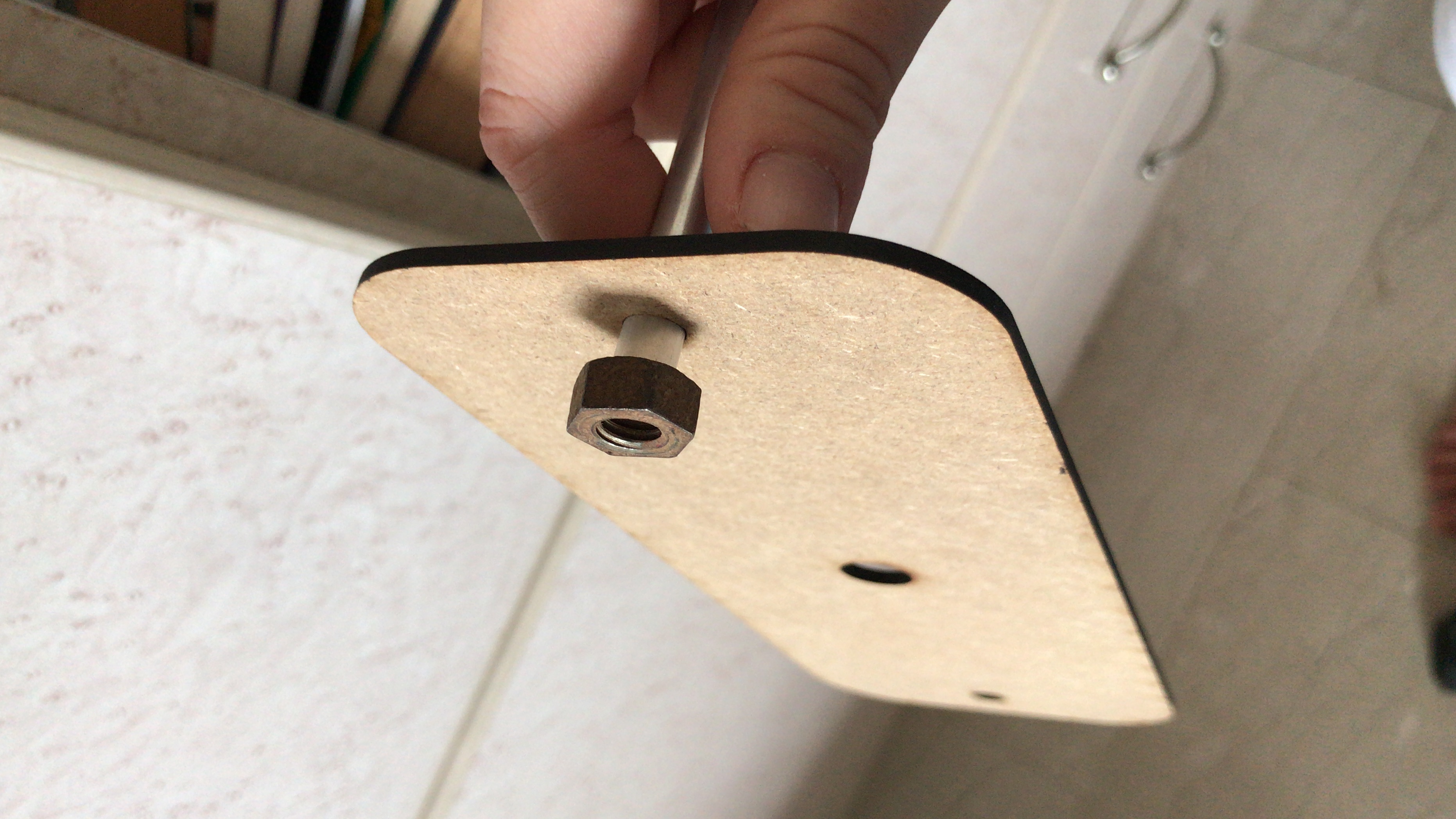
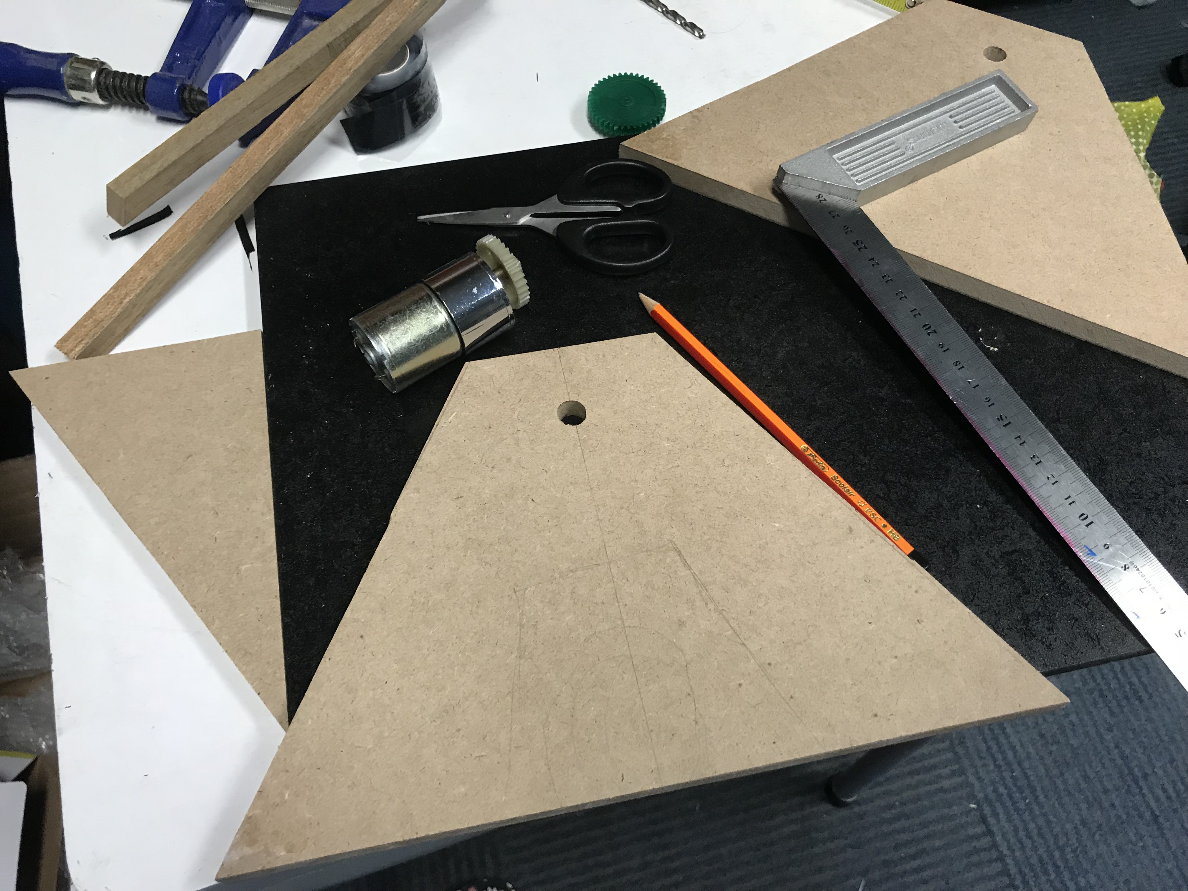
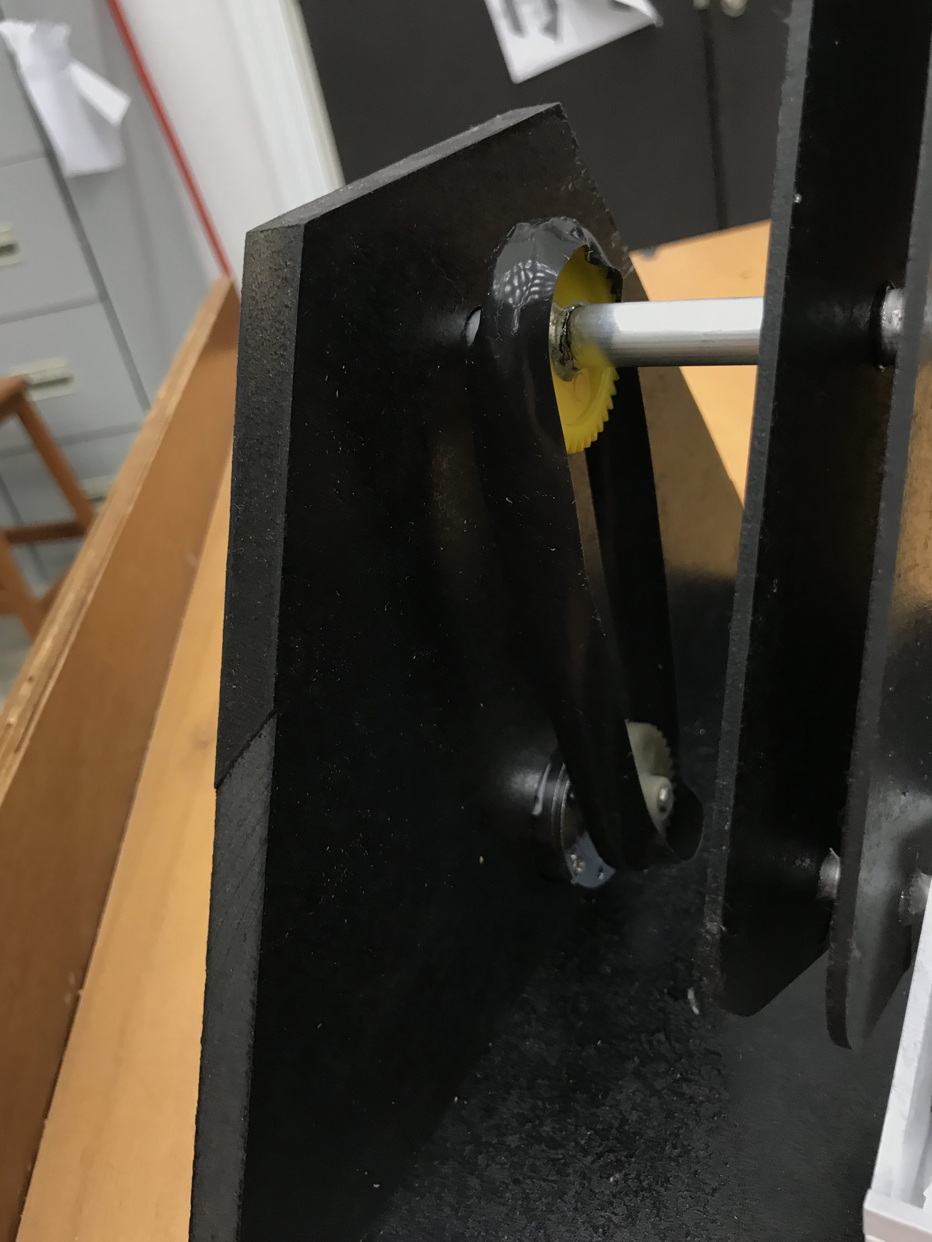
I was pretty worried about the structure and how it would actually hold together, and after having gone through the laser cutting workshop, was actually able to try it out! Here’s my process making in pictures:

Final Prototype

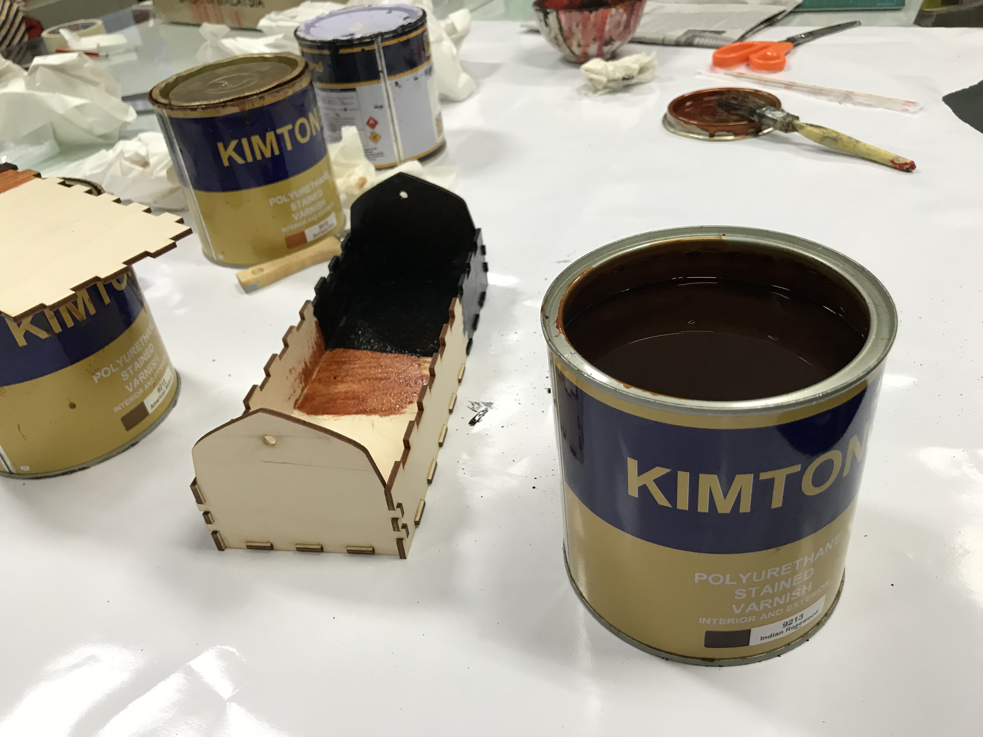
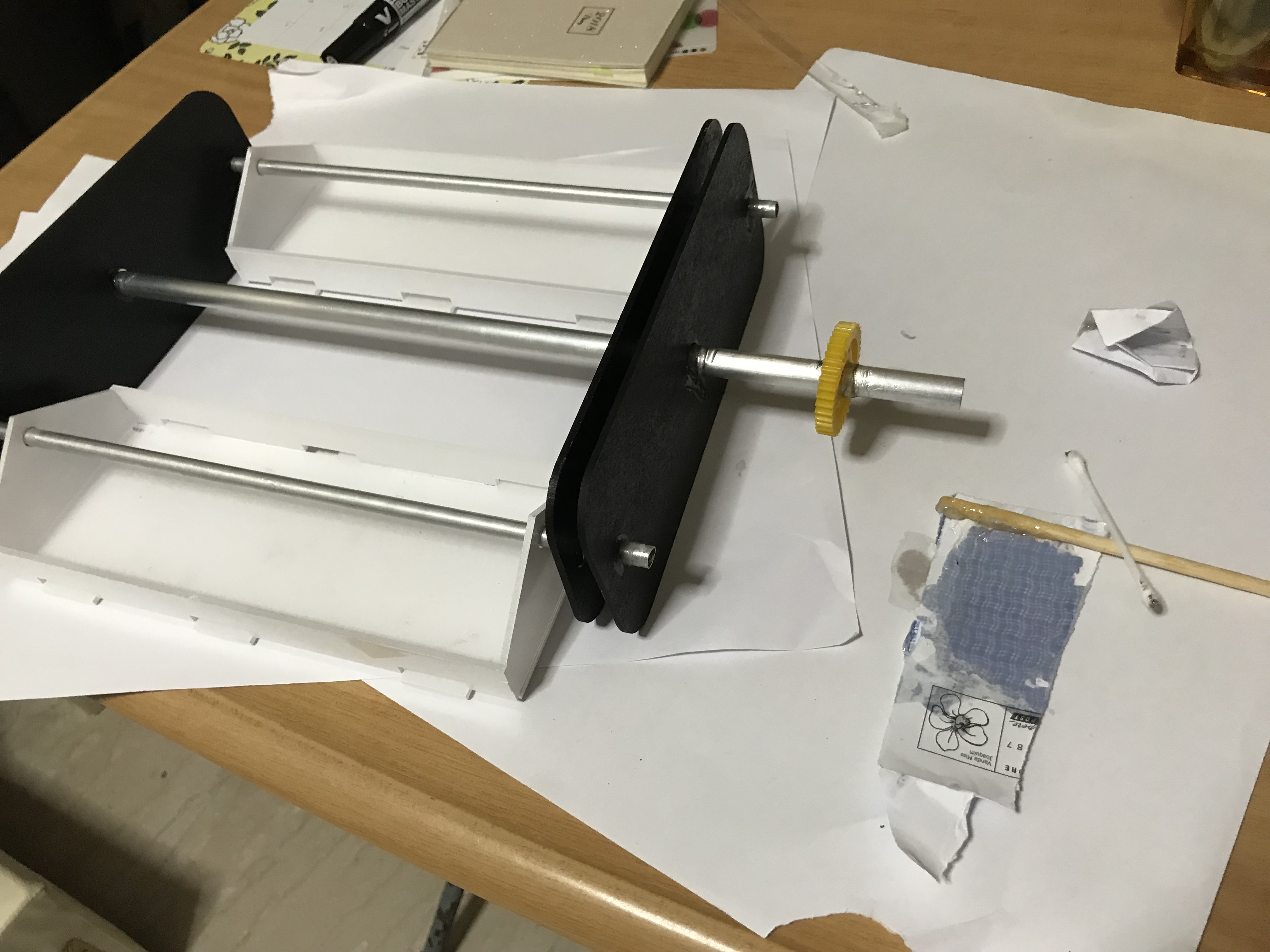
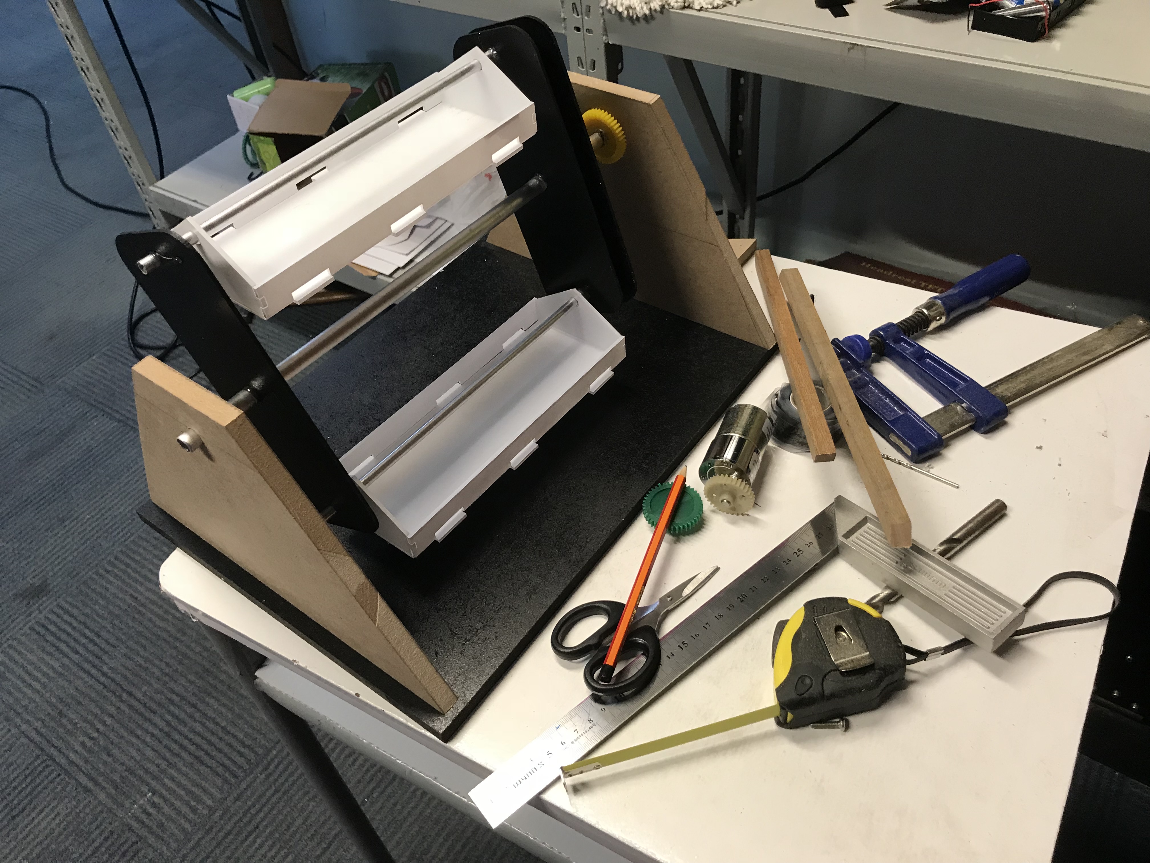
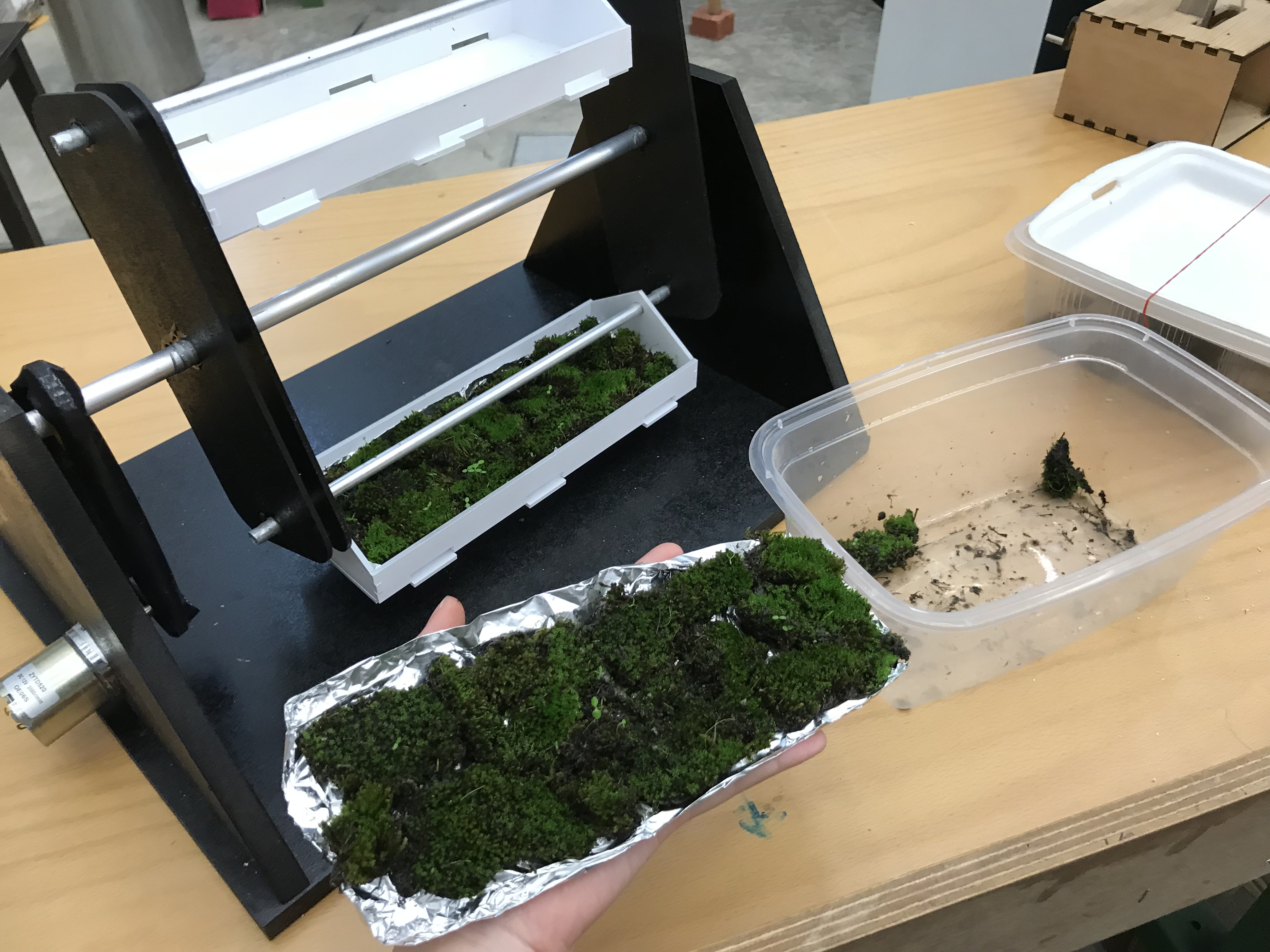
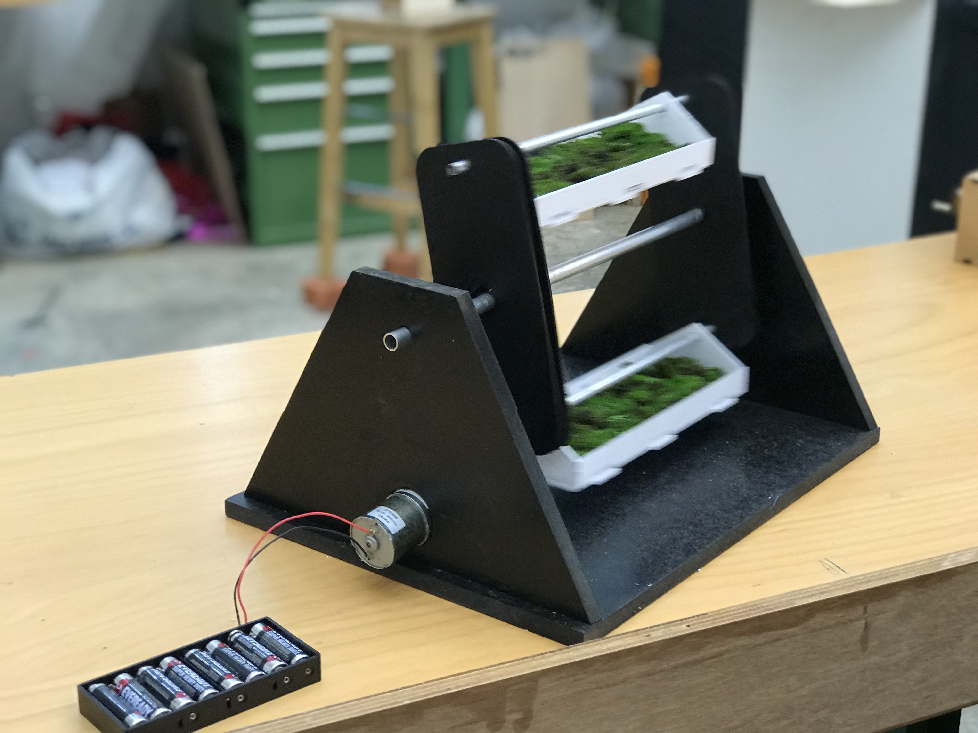
ps. moss burger is not actually the name of the machine, it’s just some pun injected (from the fast food chain Mos burger) into this otherwise nameless machine!

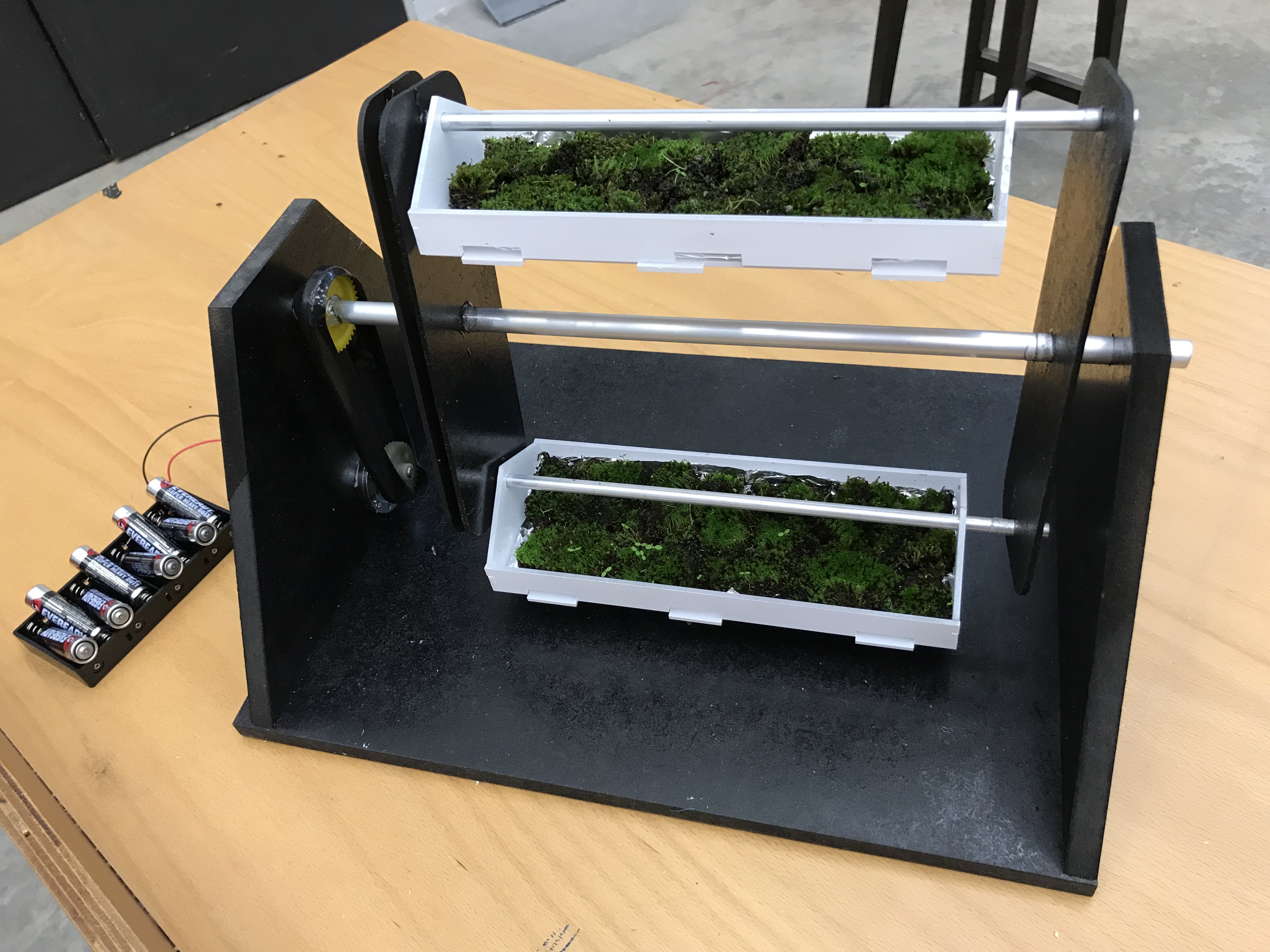
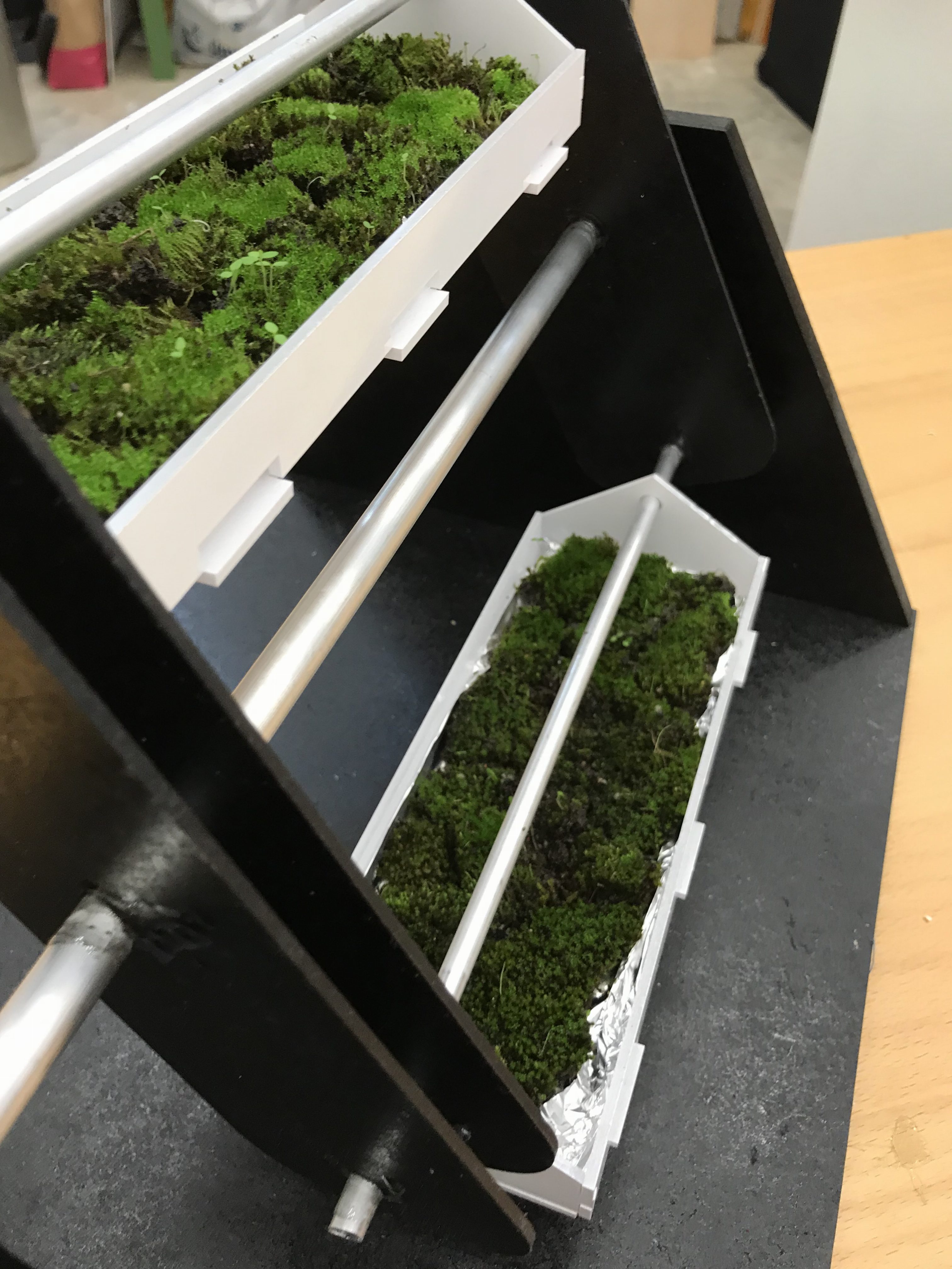
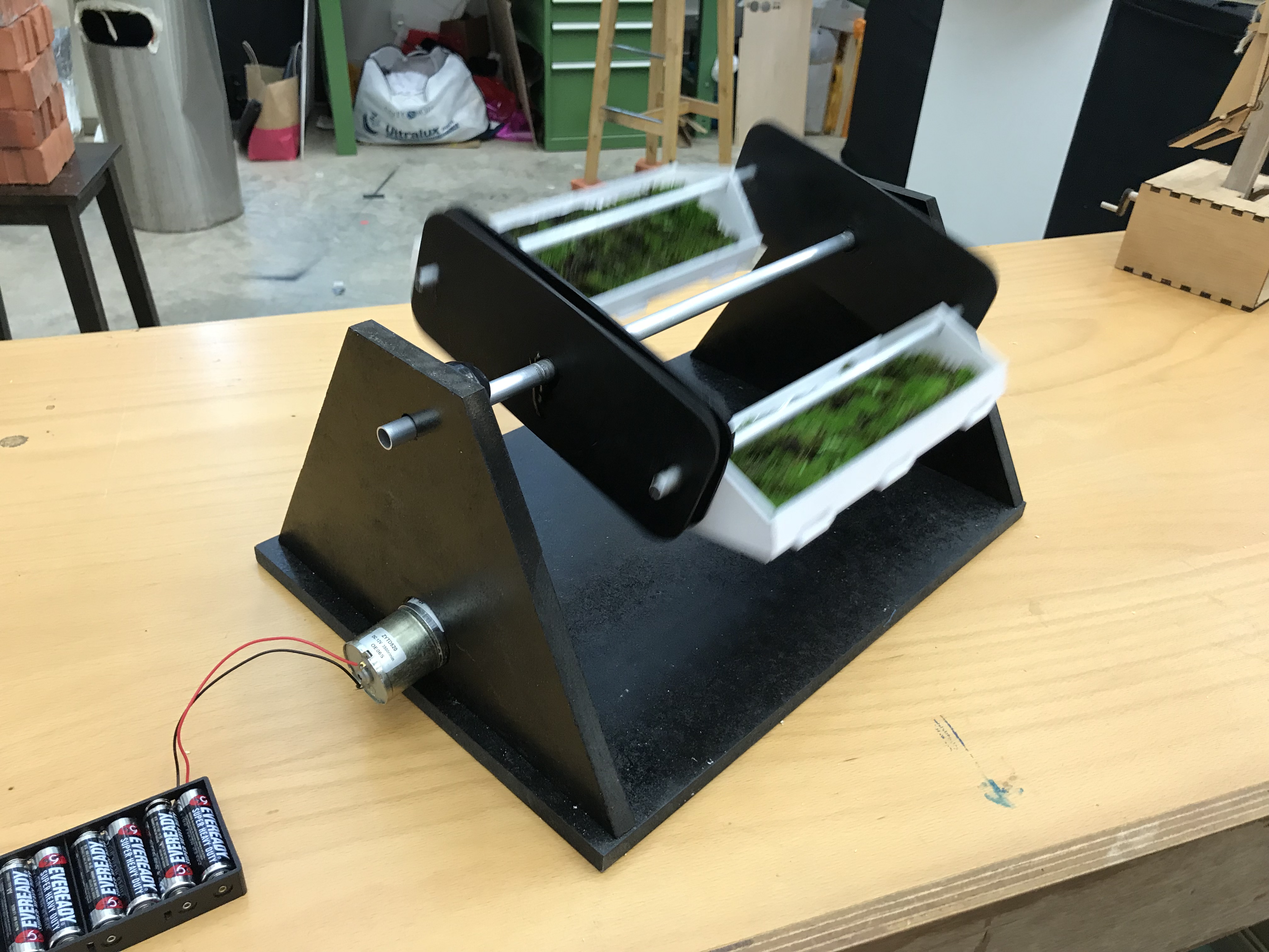
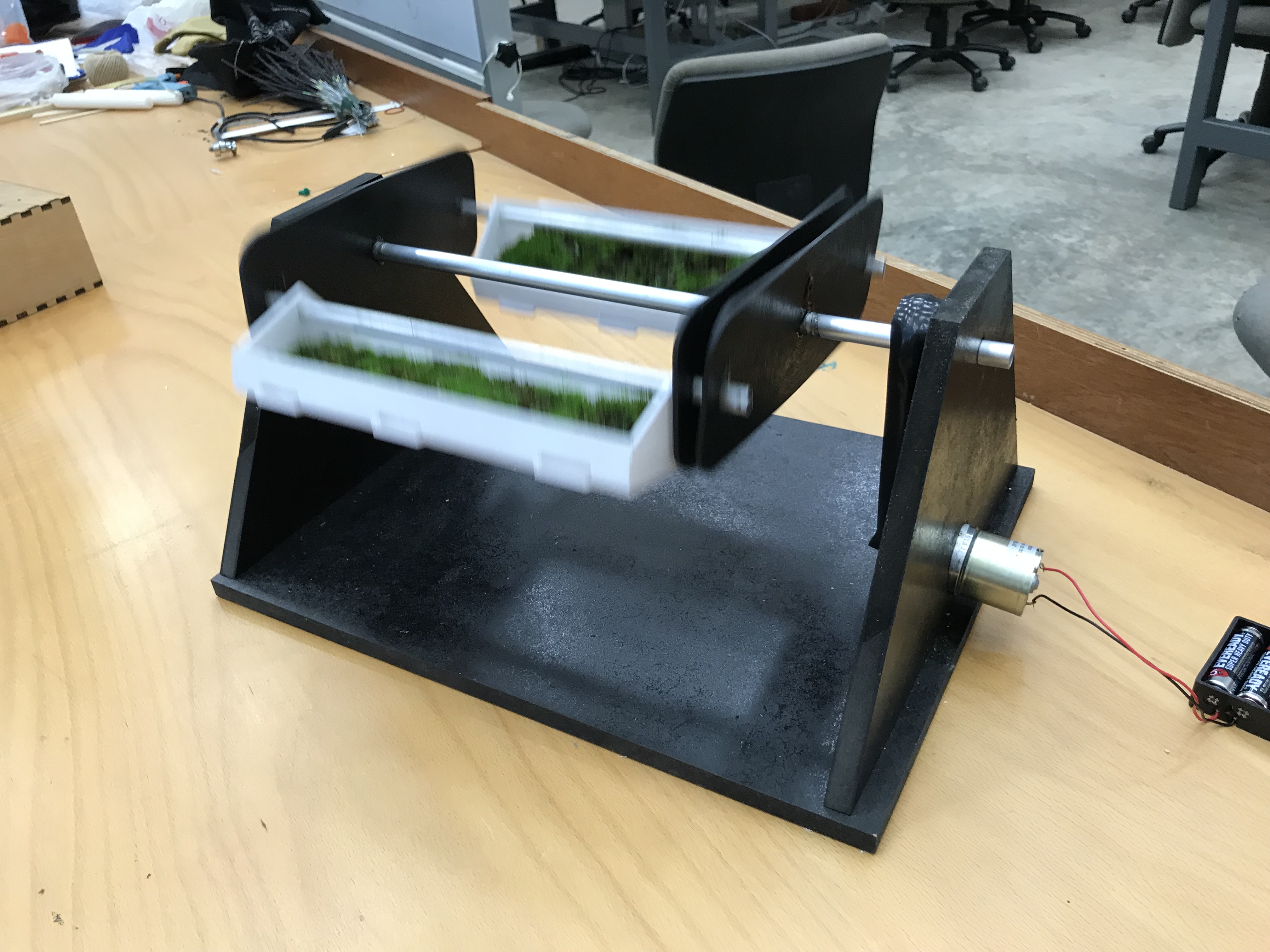
I envision this to be my final prototype (if possible)! From now thereafter, I would be working on the final machine. It would take some time though, perhaps 2-4 weeks to complete it as I wish to perfect it.

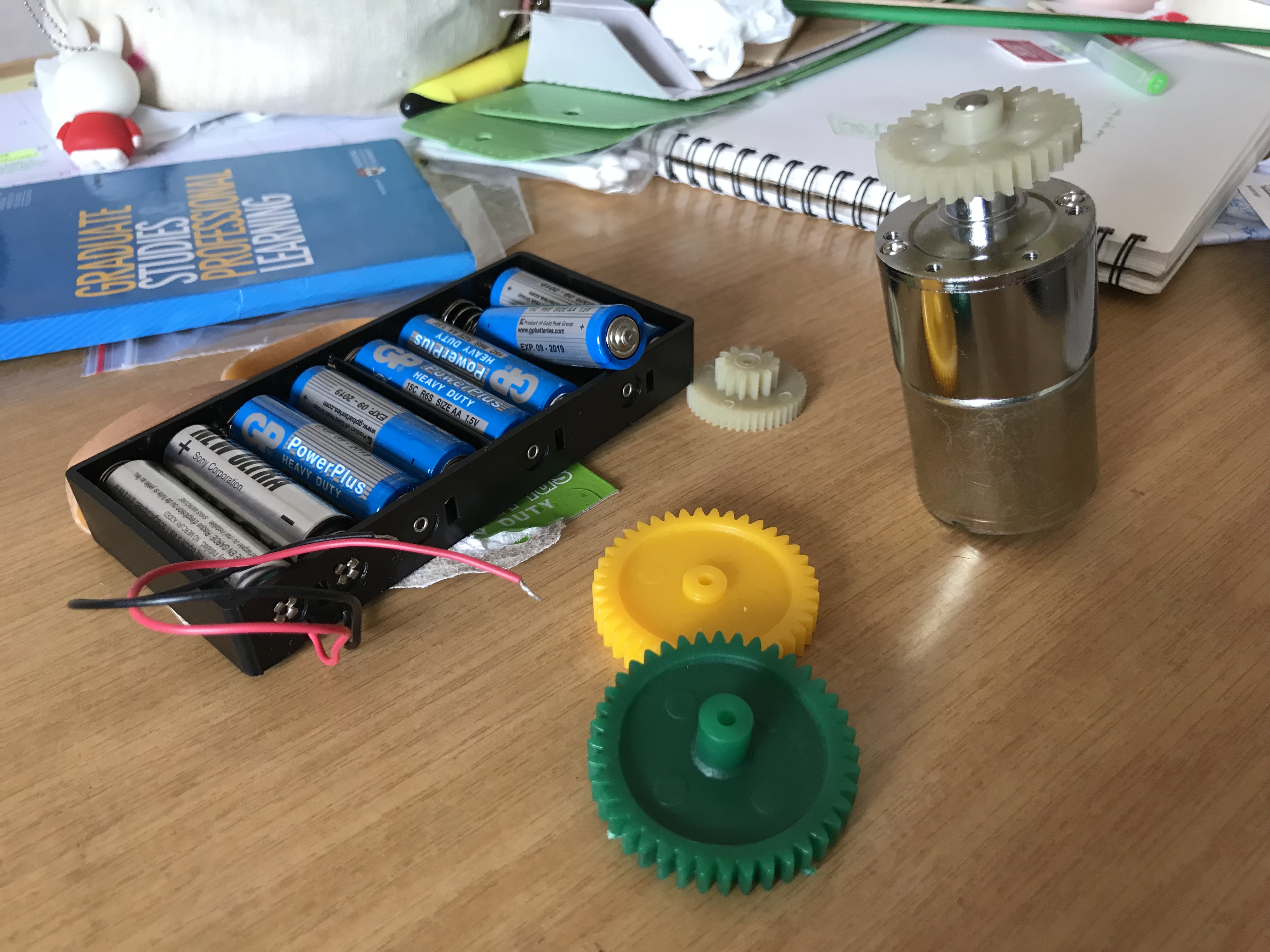
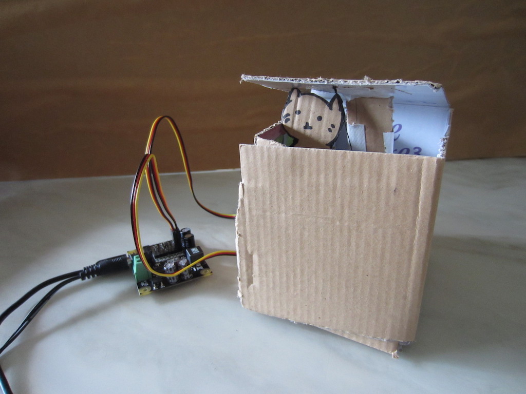
As of now, the speed of the turning it wayy too fast for my liking. I’d be experimenting with gears of different sizes and try to slow the speed down. In addition, I plan to make rotating grow lights (to keep the moss alive) to follow the movement of the rotation. However, it might take some time – my grow lights are currently still being mailed over to me, and is estimated to only reach me 1-2 weeks from now.

For the final machine, I would also make it slightly larger than this prototype. Not too large, as originally thought (initially I wanted it to stand at 1.6m height/5.24 feet) as I am not confident of my construction skills.


Projection Matters

I have not started on this yet, but I plan to project real life camera detection of the moss machine itself.


Supporting Materials (eg. pamplets, posters)

I wanted my final installation look to be a unique mishmash between the science laboratory, and a dark installation space. Above shown are mood-board references of how the final installation might look like – albeit with a slightly different colour scheme of purple, black, white and potentially dark blue.

Research Poster FYP (sample, unfinished)

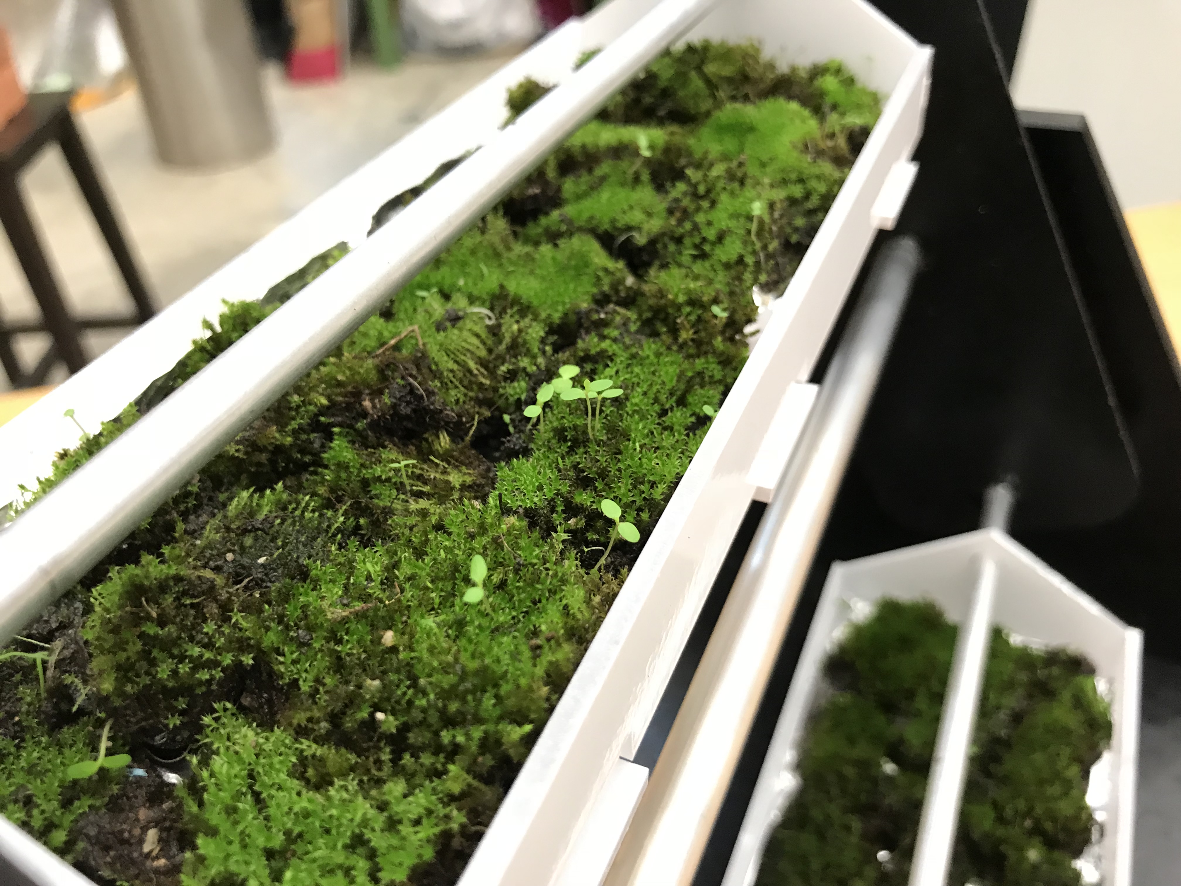
For instance, this was one of the posters I intend to display within the installation space itself. It would have real data which I collect from my investigations (eg. how many seedlings have sprouted from my moss), but placed in an authentic yet ludicrous way.


Conclusion
Over the next few weeks, I would be prioritising the creation of the machine and projections, as I am quite worried about how it would look like in the actual set up, and would require them to be ready as soon as possible so that I can more accurately plan the actual exhibit space.

I would also continue collecting data from my grown moss to be put into the poster ?

Technical Aspects and more details (FYP18)

Summarised Updates
Apologies for the delay in uploading this post! This post would cover 4 main components (making up the entire project) which I have been working on:

  1. Moss Harvesting
  2. Machine Construction
  3. Ideation/concept
  4. Projection

Let’s start!


Moss Harvesting

Initially, I wanted to harvest my own moss, continually sowing and replicating it such that it would make a mossy bed. Hence, I tried to hunt for actual moss around my neighbourhood as I thought that 1) these species of moss are already acclimatised to our hot climate. Hence, the chances of them dying during the actual exhibition could be lower. 2) Should the mosses harvested die, there is always an abundance of more mosses to be collected from the environment. 3) it was, free.

Thus commenced the witch hunt! (I didn’t pluck mosses from nature reserves/preserved areas so I didn’t flout any laws hopefully).

Out of all these local moss species, I identified at least 3 different species – codenamed species A, B and C. Out of all these 3 species, species A was the rarest (I was only able to find it on a single trunk), whereas species C was the most common but hard to transplant onto a different surface.

Some attributes I discovered from my layman observation of the tree species:

Species A
– rare
– most aesthetically pleasing in terms of moss beauty
– easy to transplant (in terms of scraping it off tree trunk)
– ‘cleanest’: not attached to any root/soil material

Verdict: ❌
Usable for project, but impractical due to difficulty in harvesting

Species B
– common
– barely perceivable height
– extremely hard to scrape off
– ‘small presence’: only a huge and enormous quantity of it would make it look substantial
– aesthetically unpleasant

Verdict: ❌
Unusable due to aesthetics not in line with what I have in mind for the moss visuals

Species C
– VERY common, abundant
– seems very hardy
– slight difficulty in scraping off since it tends to grow on tree roots/wood
– ‘flat’ surface, would prefer another moss species with slightly higher height elevation

Verdict: ✔
Usable, but might experience slight difficulties in creating a ‘blanketed’ moss surface which I had in mind for the final visuals

That being said, I did collect some of the moss in a container and will be monitoring it as my preliminary introduction into the Art of Caring for Mosses. Based on my first few days of caring for the mosses, I realised that they were indeed very hardy – without much water, or sunlight, they were still, green. It was very good news indeed. I will be continuing to monitor the mosses, and am considering setting up an experimental set up of mosses in the dark so as to stimulate present conditions of the moss within the final installation set up.

Thus, I resigned and would attempt to instead buy moss online. Initially I decided against it as this would become a considerable budget for my project but moss as the product was essential to this study, hence the consideration was overthrown.

In the current market, there are very limited sellers selling purely moss for terrarium uses. I could only purchase dry mosses, as I did not want to deal with additional difficulty of submerging the mosses inside water (most mosses are wet mosses, and much more easily available). However, I shortlisted two sellers who might be able to provide Live Holland Moss for the project. It was important to buy live moss, rather than dehydrated or dried moss which cannot be revived for the project.

Side tracking a wee bit – I actually found out the species of moss (haircap moss) which I saw in Japanese gardens, but the local market does not provide sales of this particular moss species.

It was indeed a pity, as haircap mosses are more apparent, and have a slightly more protruded surface/texture which might make the moss carpet seem more lively. Holland moss, on the other hand, had a more grass carpeted surface, making it theoretically easier to blend and create a more even moss carpeted surface.

The two sellers shortlisted are: Ecophonics and Zantelle. The budget for an estimated 17 x 12cm/6.7 x 4.7 inches sized carton of Holland moss (based on size specification given by Ecophonics) would cost an estimated $8. I would imagine that I would need ~8 clumps for each tray I would have (cost: $64 sgd for each tray of moss?).

I will be purchasing the moss soon, along with glow lights (to be confirmed and done by end of this week).


Machine Construction

This was one of the most prevalent aspects of the installation, yet one of the most worrying at the same time. For this machine, I experienced several difficulties in creating the build and rotation mechanism. As an add on from last week’s cardboard mechanism which didn’t work out smoothly enough, I created another more stable structure which I will be partially adopting into the final design.

Prototype 2 of rotation mechanism

Unfortunately, this would require much more time than expected, as there was a delay in purchasing materials and building. In my consultation with Prof LPD, he recommended essential reinforcement of the tray, and rotating arms with flange mounts/bearings, and for the rotating mechanism, implement a gear system which would control the speed and rotate both the tray and the glow lights (as another rotating mechanic entity from the first moss machine).

This gear system would be powered by a solo (for now) powerful motor, namely the wiper motor. The wiper motor is a motor originally used as the windshield wiper, and would be powerful enough to drive the entire gear mechanism. However, visits to sim lim tower to purchase this elusive motor proved to be wasted, and I would need additional time to purchase it online (via Ezbuy or Amazon). In addition, details were missing from my sketch/second prototype, thus I spent the week trying to polish up and make a working sketch and push through with the machine specifics.


Sketches

Actual and final size of machine

(Refer to above figure) The machine would stand at 1.65m, rotate at one rotation for every minute. Each tray would be 52.5 x 15 x 5.5cm/20.6 x 6 x 2.2 inches.

Details: specific gears for machine
Details: Material list for machine

(Refer to above figure) The base of the machine would be created using wood, while the arm would be made using acrylic. The gear (unlike what was sketched) would be only attached to one rotating arm, but I would be inserting a metal rod which will extend towards both rotating arms and provide stability, and hopefully, enough rotational power.

As for the tray, I hope to be able to use acrylic (as it is waterproof and able to take the misting required to water the moss daily), but am unsure of that at the moment as the acrylic might not be strong enough to handle the weight and pressure of the plants, movements and whatnots. It would take testing to iron out these concerns.


Concept

Articulating the Concept

While the last few posts have already written about the concept in different permutations, I have jotted it down to make it more concrete and less airy. Please refer to the above figure on the specifics.


Projection

Sketch of counter sensor of number of rotation of tray

Regarding the projection, I will schedule another OSS post on Friday to talk more about it. As of now, I would be utilising the number of times the trays rotate, and using this data to create imagery to be projected on a singular wall (for now).

I would require one projector for this aspect.


Analog Project [Documentation]: Cascade / Strings Installation

Ideation

Initial Project Idea at ADM Pond area

I initially wanted it to be like an artificial waterfall, which would cascade down the roof and into the ADM pond. Should I have placed it here, my ideal colour pick for the strings would be a cool-themed colour.

After a round of consultation with prof and classmates, I realised that 1. the interaction was lacking 2. it was more of a sculpture, and did not lure others to interact with it.

Also, I realised that it might be a safety hazard with regards to hanging it on the roof. The strings might tangle too, but I was ready to secure it to the bottom by weighing it down. However, I decided to switch it up instead, and shift the installation to another area.

Idea no 2


Hence, I transplanted it into a singular, rectangular installation (instead of previously fronting only the edge). Within the installation there would be scissors, which would ideally tempt others to join in and cut the strings.

Initial Sketch

Initially, I wanted to place it in the corridor and use shower rods to secure it up. However, safety issue was to be taken into account, and I had to pay extra to purchase shower rods – hence, I decided to place it in the level 2 empty area beside the stairs (level 2 to 3 stairs) in adm. There, I could use strings to secure it.


Creation

Sample

The top supporting the strings would be a foam-board, chosen as it is lightweight, relatively durable, and also, able to support some degree of piercing. The strings were meticulously arranged separate from another at a distance of 3cm, measured out and indicated on the board.

After finishing my preparations, I had to meticulously string those on the board. Initially, I planned out 90cm for each string length, but measuring them one by one was taking way too much time hence I decided to just estimate the length. In addition, the strings were pretty much tangled up so I had to resort to estimation else completion would not be a reality.

Also, I intended for the scissors to be of a different colour from the strings: to be easily seen and lessen the risk for walking facefirst into it, and for it to be a prominent object (with a status) within the artwork itself.

How to string 101:

I decided that the lighter colours would be on the inside; as the chosen area might be a little dim at times, and the inner colours would be dulled. I chose white as it was a metaphor for clarity, upon passing the darker colours on the outside. In addition, it could create a density which I wanted.

Upon completion, I lugged it to adm to be hung up. The four corners were tied with black string to be suspended.

4 corners of the board, hung up by strings tied to the surrounding poles.

I intended for the installation to be at a height whereby the bottom of the strings would be touching my chin; at this height, it would create a more immersive feeling for when the viewer looks up, all he sees are a cascade of strings.


Completion

Completed

Initially, I meant for it to adopt a squarish format, of which my chosen width would be at 1.2 x 1.2m. However, I ran out of strings, hence I shrunk the size down to about 80cm x 1.1m (estimated).

When seen from the 4 different sides, the strings look slightly different, partly due to the pattern of stringing and lighting conditions.

Yi Xian as my model – as a reference for the height of the installation

The strings also got slightly tangled up, but due to the quality and weight of the strings (specially chosen for such), it was generally weighed down and added to the beauty of it.

One point I noticed was that the scissors were a safety hazard. Particularly, that was the reason why I opted to purchase childsafe scissors with a small blade. However, if the viewer does not close the scissors after using it, the blade might hurt him/someone else.

When looking from the bottom, the middle of the board is noticeably white.

Colours from inside out:
white > yellow-white > pale pink > hot pink > royal red > dark brown

Definitely, this installation would be much more immersive if it was larger; when seen from afar, it appears small and isolated. However, I am thankful that it managed to achieve density and the experience that I sought for.

It would also be interesting if more people could interact with it, and see how they would cut the strings.


Cat in the box! / Phigets Servo-motor controller

image1

My little cat! Created out of recycled cardboard, with a mishmash of different scotch tapes. As in outer side of the cardboard has graphics printed against it, I decided to invert it, thereby cutting the box up and attaching them together to create my very own box.

IMG_3323 copy

Strings pull the lid close, and the small piece of cardboard pushes the lid up. The cat itself was a makeshift shape of a cat.

IMG_3324 copy

As seen. In total, I used 2 servo motors – one to control the cat, the other to control the lid. Perhaps, with better crafting skills, I would be able to cut the number of servo motors down to one. To do this however, I require a larger box – currently, the box is palm-sized – and more ‘attachments’ to attach the cat to the handle/gear that pushes the lid open. To simplify things, I decided to do without it.

IMG_3325 copy

IMG_3326 copy

Peekaboo! The cat comes out a few milliseconds, after the lid opens.

IMG_3327 copy

IMG_3330 copy

Attaching the cat box to MaxMsp via a cable.

IMG_3341 copy

The inner workings of the cat box – one servo motors is raised in the air, the other attached to the ground.

When one speaks to the box, the lid opens – but no cat in sight! For this is sure some shy cat. Hence, speak louder, but what you say does not matter. The cat will appear for a short while, then disappear, if the threshold volume has been reached. Otherwise, only the lid will open.


See it in action:

In hindsight, I would have included an additional feedback – where the cat would mew back at the user, via an added soundtrack into the max patch. Pertaining to the documentation, I would have also put in human interactions (which I forgot to record earlier) – perhaps, of the user drumming the lid of the box, or attempt to catch the cat.


Patch used:
Finalised Patch Cat in the box

Lights, action! / Gyroscope, lights and sound

This prototype is a further development of the previous ‘swish the sound’, with the addition of chauvet lights.

When the gyroscope is tilted at an angle, there are two responses:

1. Sound is played at the angle the gyroscope is tilted at, and

2. Red light intensifies at the corner the gyroscope is tilted at, washing out the green

Sound is created by using ambisonic, while the control of the light was made by scaling the x and y coordinates of the gyroscope.

Screen Shot 2016-03-28 at 9.23.14 PM

Screen Shot 2016-03-28 at 9.23.39 PM

Scaling of the gyroscope was slightly different (ie. improved) from the previous sound/graphics/gyroscope patch. Now, the greater the tilting of the angle, the greater the intensity of the red lights. However, several improvements could be made:

  • alike to ambisonics, which had a smoother transition when the gyroscope tilt changes, transition between the different chauvet lights could be smoothed out.
  • perhaps the intensity of the ‘chosen’ chauvet light could also be dimmed – this I tried, but could not successfully manipulate the lighting such that it stopped blinking (ie. setting the minimum threshold)

Swish the sound! / Documentation, Process

A week ago, we had our first experience matching the gyroscope’s movement with the amplification of 4 different speakers – one at each corner of the room.

Here is the previous patch I did, which matched the gyroscope’s pointed direction (top right, bottom right, top left, bottom left), to triggering the speakers in the room, corresponding to their location. For e.g., point top right will trigger the top right speaker. When triggered, the speaker will switch on, when not triggered, the sound from that particular speaker will switch wholly off.

Screen Shot 2016-02-29 at 9.38.26 PM

Comments from the ground mentioned that perhaps, utilising the volume instead of directly switching the said speaker on/off will allow for a more ‘flow-y’ effect when switching to and fro different speakers. At current, the speakers were discrete: individually separate and distinct.

In addition, the randomising effect of coloured rectangle was indeed distracting. Below is a sneak peek into how it looked like:

One perplexing issue with the (x,y) values was that it was not stable enough, such that the distinction between the third and fourth speaker was not clear enough. Hence, switching between speakers may not be accurate enough for 2 corners.

Perhaps, the curve followed a log curve, instead of a linear function, hence by simply isolating particular sections of the x or y section and extrapolating it with relation to the speakers remain inaccurate.

From here, I decided on trying to covert the log curve into a linear curve, by utilising angles. I used this equation:

‘If tanθ = b/a, then θ = tan^-1(b/a)’

b being the side of the triangle opposite the angle, and a being the side of the triangle gating the side of the unknown angle. However, I fixed the starting ‘corner’/tip of the unknown angle at a given point in x, so one is able to differentiate between angles among all 4 quadrants.

locate820160229061157


Meanwhile, please refer to the below patch:

Screen Shot 2016-02-29 at 9.24.29 PM

I used ‘atan’ to find the angle in radian, after which I converted it back to degrees by multiplying it by 57.2958. Hence, by ‘split’, I tried to match each angle to the ‘gain’, or the volume of each soundtrack. I also attempted to put in 4 different soundtracks to correspond with the 4 speakers (which is also easier to identify which speakers were playing), but ultimately decided to simply stick to 1 soundtrack. Each sound however, was individually recorded from real-life.

However, the angles, while calculated correctly, still tended to jump around, making the change in volume for all speakers jittery. Hence, for recording purposes, I decided to first stick to my initial patch where each speaker was turned on individually, but will continue troubleshooting the angles at a later date. Potential reasons for this jump include: the extrapolation of the angles were too small/huge, hence it was too jittery? Else, it could be that the ‘boundaries’ for the graph was too huge/small, hence the change in angles were too steep/quick.

As for my graphics, I decided to play with jit.gl.gridshape, to create 3D shapes. My intention was to have a sphere pivoting in 3D space. However, in playing around with the z-axis, it was difficult to specifically alter the x,y coordinates to move the z-axis. Hence, I decided to focus on the 2D visualisation of the sphere instead. Initially, it worked perfectly, with the sphere moving in the direction of the gyroscope. Despite my initial success, an unknown error cropped up the next day, and I could not get the sphere to change its position. I also played around with jit.gl.lua, lua being a scripting language which could be input into max msp. I wanted to use the x,y coordinates to replace mouse click, which activated the graphics within the jit.window, but was unable to figure out the mouse click function, which seemed to differ from the mouseclick from jit.lcd.

Therefore, I decided to stick to what I did initially: use jit.lcd to draw a moving rectangle. I would instead fix the perimeters and colour of the rectangle this time round, so that the graphics would not be too flashy.

“Music Instrument” [the Tun-tun]: Final Product / Assignment 2

thumb_IMG_0992_1024

thumb_IMG_0993_1024

thumb_IMG_0994_1024

thumb_IMG_0995_1024

thumb_IMG_0998_1024

Depicted above is the final prototype of the tun-tun.

Functions are as stated (from top-down):

  1. Tapping top of head – triggers a beat once
  2. Pulling of left ear – controls the volume, and triggers the melody once
  3. Pulling out/pressing hard on tip of tongue – triggers a voice on repeat, pull it out again to switch it off
  4. Slide the “voice box” up and down – change the pitch of the sound effect

All sounds are recorded in real-life; however, they do not sound melodious when mixed together. New sounds can be input(ed) to replace the current sounds.

Physically speaking, the product stands at my chest-level.

thumb_IMG_1002_1024

thumb_IMG_1003_1024

Max MSP patch as depicted below:

Screen Shot 2016-02-15 at 6.56.41 PM

See it in action:


“Music Instrument” [the Tun-tun]: Prototype / Assignment 2

A singing head!

20160201090933

tuntun

Image of tun tun taken from here

Does it not remind you of a tun-tun (pig-stick used by the Iban people in Borneo/Malaysia to lure pigs into traps)?

Much physical resemblance between the sketch draft and the actual object; yet inspiration was not drawn from the tun tun. Sole commonality remains their names.

My project, aptly named “Tuntun”, features a sphere-shaped human-like head, where controls are placed around the head, eg. mouth, top of head, ears, to mimic a human making sound with his own facial features.

Below shall show a sketch of the areas with sensors:

Sketch sensors

At current, the ‘head’ is not placed in the order order and position. Further improvements in the patch are left to be desired.

20160201090951 20160201091051 20160201091103

The patch is currently incomplete, but here is a quick insight into some parts of it:

I used Gizmo~, Buffer~, Groove~ in replacement of playlist. Certain tweaks are required – for instance, the song abruptly stops playing when the trigger switches the toggle off. I am trying to include a timer, or delay, to allow for the entire soundtrack to play before it switches off.