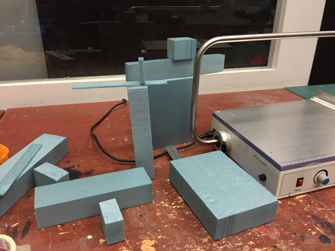
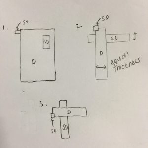
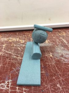
Model 1

851440807_5640533802262653871

851518213_16052241341946294056 851517925_8850676307237332428
851519075_7547660850948697585
851516823_14215454072343682306
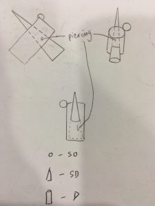
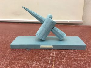
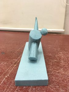
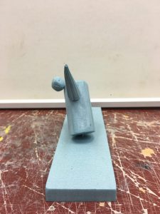
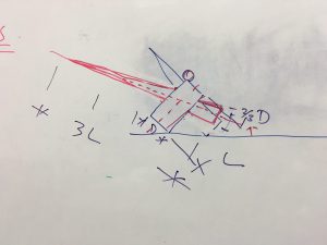
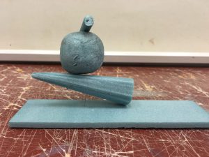
For this model, I was eager to try piercing as previously we had only worked with rectangular volumes which are not as dynamic and complex. However one major flaw of this model was that the D and SD were not easily differentiable as they appeared to be of about the same mass. Ms Cheryl suggested that to make it more apparent which is the SD and D, I should make the cone the D instead and make it 3 times as long as the diameter of the cylinder as seen in the last photo. She also suggested that I allow the cone to “float” by decreasing the angle between the cone and the base.

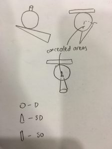
One other mistake I had made was that to pierce the cone, I did not remove a section of the middle of the cone but instead just cut it in half and pinned the 2 ends to the cylinder to mimic piercing. I had not thought about how in actual piercing, a part of the cone would be concealed inside the cylinder! This is something to remember for future projects because had I remembered to remove the middle part of the cone, it would have been shorter and perhaps the SD and D would be more apparent.
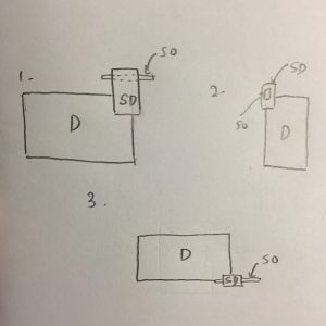
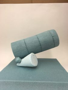
Model 2

851517995_1820093921589199284
851517861_9206025160904373027 851518944_11167141746433318546851519115_12093995305881288601

851439473_13748689629148984279

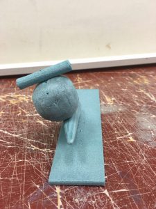
This was the model I chose to work on as my final model, but major changes were made to it such that it doesn’t really look like the same thing any more haha. In the final model the roles of D and SO were switched so in the final piece, the cylinder is the D and the sphere was majorly decreased in size so that it was barely even visible between the cylinder and sphere.

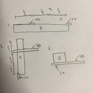
For this model, I tried to give it good proportions by making the cone base 2/3 the diameter of the sphere while the cylinder base was 1/3 the diameter of the cone.

I was not keen on this model at first and did not attempt any piercing or wedging. However, Ms Cheryl showed an interest in this model and I found the arrangement of the pieces to be interesting hence I decided to work on it for the final piece (seen below).

851516832_9205591319517536730

curvilinear-volumes-pg-3-plain

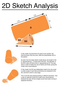
curvilinear-volumes-pg-3-plain-compressed

(please click the link to view larger version)

As you can see, it looks nothing like the above figures. It really goes to show how much difference just a few small changes on paper can make to the model. (:

Rectilinear Volumes

Sketch Model 1

850615113_14856070889637946217

The first sketch model was the one my final model was mostly based off of. In this model I attempted both the wedging and piercing techniques, by piercing the SD piece through the D and wedging the SO into the D.

As seen from figure 2, the D and SD were of almost equal thickness, due to having been cut out from the same piece of foam. Hence in the final model I re-cut the D from a thicker piece of foam.

Sketch Model 2

850617300_3662170729148968250

My final model was also partly based off this sketch model, as I wanted to attempt a model where the SO is placed on the SD rather then the D. In this model, I also attempted both piercing and wedging but applied it in different ways. The dotted line in figure 1 shows where the SO was pierced into the SD, while the SD was then wedged into the D.

This model is flawed as the SO is too long, hence from some views such as the one in figure 3, it appears longer than the SD which causes some confusion. While I attempted to avoid this confusion by making the SO 1/3 the thickness of the SD, it was still significantly longer as it had to be pierced into the SD. Learning from this experience, in my final model I chose to wedge the SO into the SD rather than piercing it so that I would be able to use a SO that was less significant than the SD from all angles.

Sketch Model 3

850619417_13447468185732959998

This model was least like the final model as I preferred to work with a D that was more block-like and not as long as this one. In this model, only wedging technique was used.

This model was not viable as you can see from figure 1, where the SD appears to be much smaller than the SO. This is because while the SD was a longer piece, it was also very narrow and its width corresponded with the length of the SO. Furthermore, in figure 3, the SO is only very barely visible due to being wedged too far into the D. Hence from that angle it might not be readily apparently to a viewer that there is a SO piece.

Nevertheless, the model is not without merits. Figures 1 and 2 show that the placement of the SD is such that it is placed exactly 1/3 down the D, giving it more visual coherence.

Conclusion

While all models have their pros and cons, ultimately the model I favoured most and chose to base the final model off is Sketch Model 1. This is due to the flaws in models 2 and 3 which I had stated above, but also because it was the only model which had D, SD and SO facing 3 different axes (x, y and z) which makes it visually the most coherent of the 3 models.