
5.0 Club
5.0 Club attempts to alleviates problems that people normally face in a club/ party. 5.0 Club has 4 stations, namely the Registration Booth, Drinks Bar, DJ Station and last but not least the Light Station.
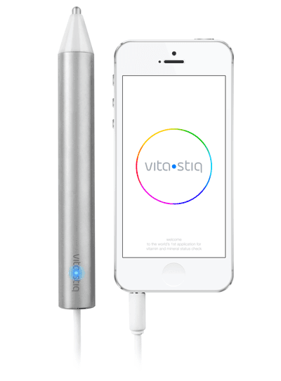
At the Registration Booth, participants will pick an RFID tag according to their favourite music genre. They will then register their chosen tag with their name, favourite drink and favourite colour. This RFID tag is the main driver of 5.0 Club, as it is the device that gives participants their identity.
At the Drinks Bar, participants can easily order their drinks simply with just a tap of their RFID tag on the reader. This makes the job of the bartenders easier, for they do not have to strain their ears to get orders over the loud music and also allows for participants to refrain from having to raise their voices when making an order.
When participants tap their RFID tag on the DJ Station’s reader, music will be played according to their favourite music genre that was chosen earlier in the registration process. At the same time, the light of the disco ball will also follow the beat of the music.
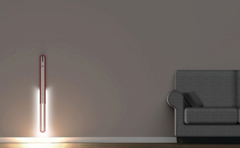
In addition to the above, when participants tap their tags at any one of the readers situated at the ends of the LED strip, the LED strip will light up in their favourite colours. For the LED strip to fully light up, there has to be two people with the same favourite colour registered in their RFID tags tapping at the same time. This adds in an element of fun and interaction for the participants, and also acts as a conversation starter.
RFID TAG
It is the first time we are handling RFID and it took us quite some time to figure out the whole code. Using the examples provided in MFRC522 library, we get to retrieve the tag ID with the code below. Where it looks for tag available, retrieve the byte array as hex values and convert to serial, making it readable. This way we are able to individualise every RFID tag according to their tag ID.

Registration Booth
At the registration booth where we will key in their name, favourite drinks and favourite colour. In order to store the data in the RFID tag, we will need to place it in the Block Array. In the code below, we store the participant’s name in block 1 and favourite drinks in block 4 which will help us in retrieving the data later on in Drinks Bar.

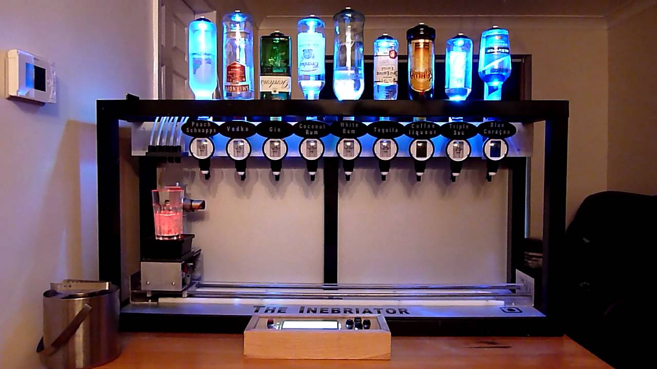
Drinks Bar
After storing their favourite drinks at the registration booth, they are able to communicate with the bartender with a tap of their RFID tag. We are able to retrieve the data from the block array which was store earlier on in block 4.

Light Station
Because we weren’t confident with RFID or actually coding in general. We started the codes for this station from the mere basics. Simplest was to first control LED bulbs instead of LED strip. And instead of RFID, we tried using buttons at first. So basically, we linked up different buttons to different LED bulbs. After which we replaced LED bulbs with LED strips:
Then we moved RFID in. We have two RFID reader at this station where they have to communicate with one another to trigger the LED strips. Firstly, we have to assign names to the reader so that we are able to retrieve data from the respective reader correctly.
Using the library’s example (just above), we tried to recall the data so that we can command it to on/off the led. However, the difficult part is that the data attached to the RFID tags are stored as bytes, hence we are not able to simply equate those to words as it requires ASCII translation.

buffer2[i] is where translation takes place. Thus, we cannot do if ((uint8_t i = 0; i < 16; i++) == ‘Felicia’) { do this…….}. We also could not do Serial.read () because it still could not translate into Strings.
Thankfully, we found another code that does the translation separate from the print. Although it changes our initial idea a little, this code can read and store the RFID tag’s UID. Thus, we decided to trigger all our commands base on the UID.
Below is the translation taking place. With this, we can simply equate ‘strID1’ to the UID.

With this, we went ahead to assign the commands. To trigger the LED strips at respective station, we have to allocate all the individual tag ID to both reader and also assign the colour. Thus if any one of the station detect the right tag ID, it will light the LED strips at each ends.

To allow the linking of both station, both RFID tag has to have the same colour allocated to them. Therefore, if both station detect the correct tag ID with the same colour, it will connect both end together.

Initially we wanted to have more station for the interactive element, however we tried using master and slave code where it allows multiple Arduino to communicate with each other but it was not working well with RFID reader. We had trouble sending real-time data from the slave to master. First, we used buttons to try sending something from slave to master to trigger the light and it works. When we change to RFID, the wire.write is only able to send characters as in digits instead of alphabets and strings. Thus we asked the slave to send number 4 when tag ID was detected.
Slave:

When master receive 4, it is suppose to print “RED” and also set the LED strips colours to red. However, it is not reading the message send by slave and it is not printing anything.
Master:

Although we tried to work on it a little more, there still seemed to have issues for extracting data from either of the readers:
While we managed to solve that with LPD’s help, the next step adding more RFIDs really made the last straw. Because we had 4 RFID readers, 2 attached to each slave, the master became really confused to which slave it should get data from and also which RFID reader should go first.
Also, look at the wire-mess situation when there are multiple Arduino and multiple RFID readers:

Hence, we decided to stick with 2 RFID, 1 Arduino as explained earlier.
DJ Station
For the DJ station, we have 2 parts that utilises 1 Maxmsp sketch and 2 Arduino Sketch in total. The first part is where we link RFID to Maxmsp, and the other part is to link sound sensor and LED strip together and finally piecing the two parts together.
RFID to Max
Initially the main plan was to have led strip pulsating to the beats of the music just like the visual effects we often see in clubs or parties. With the help of some online source code by Hyrulian about how to code led lights to pulsate with the beats, we tried to connect processing with Arduino by using the minim Javasound library to analyse the beats in a music and linking it to led bulbs on Arduino thereafter.

However, one problem we faced here was that it requires more effort to input our own songs and playlist here in processing. Therefore, after consultation with LPD, he suggested that we could add in RFID element to our light Dj and also the element of music collections. In terms of music collections, we realised that it will be more efficient and easier to handle music with Maxmsp. The piecing up of the music playlist was quite smooth although we faced some problems with serial connections between the two applications, eventually, we managed to solve it with some trial and error and with the help of LPD too. Some of the code we managed to come up shown below:


The way we link up RFID to Maxmsp was quite similar to the light station and tag each RFID fob with a number which will link to a numbered playlist in max where we made max un-code the numbers and pack it up again to send numbered signals for each playlist. This process is almost an immediate process and the music can be played instantaneously.
LED Lights Beating to Music through Arduino
With the experience of how to allow the application to unpack the beats and pitch of a music, it was much easier to deal with this in Arduino. We extract some ideas like how many milliseconds should the Arduino read for it to detect a high status which will lead to a change of colour, the discrepancy readings(threshold) and how they should be handled, min and max readings from the sound sensor(takes us quite a bit of trial and error to get the perfect reading) etc… One problem we faced was that many sound sensors we experienced have low sensitivity by analog reading, especially the ones produced by Arduino, hence, we a different sound sensor by Adafruit, and while it wasn’t the most sensitive sound sensor out there, we managed to deal with it through experimenting values between 0-1000, in the end, we find the range 100-200 to be the most ideal maximum range. The main problem that we were stuck on for a long time was how to code the led strip to light up with respective colours according to the beats. The transition from on colour to another colour was also one of the problems we faced.
With reference to the Arduino website, we made Arduino plot a curve of the sound is receiving and create an output using the curve.


This way, it will be easier for Arduino to understand when to have a colour change at each different intervals. A base(songmode) is also created such that the system will know the range of colours that it can pick by reading whether it is in high state or normal state. Initially we wanted to create different colours for each values to be read by the system, however, the system would get too confused form the values and we kept getting errors from it. Therefore, we decided to plot a curve and a range for high and low values colour and rely on the system to pick the colour it will display instead. Although it was a lot of trial and errors but we eventually managed to make things work out smoothly. By linking the sound sensor with RFID and Maxmsp, we have our DJ station setup as shown below.
Overview/Setting Up
With weeks fighting with RFID, Arduino, LED, Maxmsp and Sound Sensor in the IM Lab, we knew that shifting all of these to the TRUSS room will not be easy.
And indeed, there were so many trouble shooting we have to make because we were basically re-wiring all the devices and we needed them to be seamless in the TRUSS room.
We used high chairs as our device stands and only show the RFID reader bo on top while we hide everything else underneath the chair with black cloth covering them. We also had to tape the wires in place so that they are secure and ‘un-seenable’.
And, our final piece before the showcase is as such:
Further Enhancement
We would like to figure out the problem of having 3 Arduino communicating together with RFID reader so that we can increase the number of station for our light station to allow more interactivity in it. Also, we would like to input our own visual effects(which was one of our initial plans) that will beat according to the music too.