To understand what to plan for, I would need to understand the nature of the project. As the task for completing a physical + mechanical project differed far from a virtual-screen-based project like games and visuals. There will be more restrictions in doing a physical project than virtual one due to the nature law of physic, material and cost.
Money Problems:
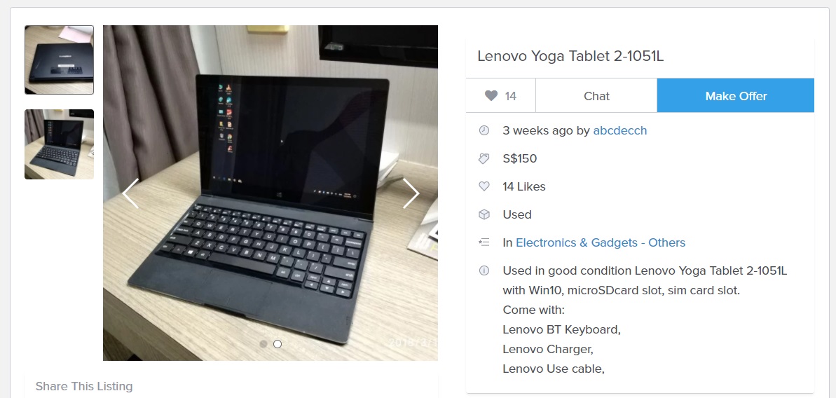
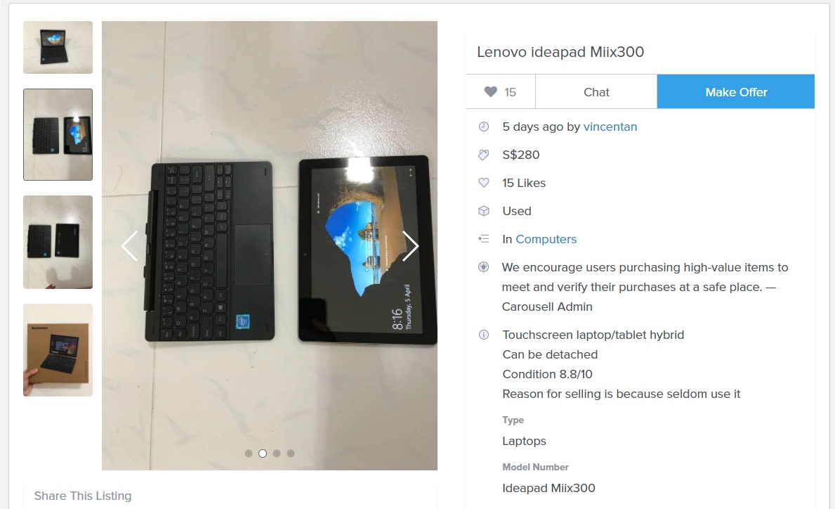
As for building a few robots will cost me quite some money, budgeting will be even more important than time planning, as for where the monies come from, I will probably save up from selling things online and work studies and treat it like a commitment because I think that no one is forcing me to do anything and its all my resolution to fund my own project.
 I had thought about asking for sponsorship and that may even happen if I have to. (especially for the batteries that I will be using in the robots, these little things must be of great quality due to safety issues while a good + durable + high capacity + low weight battery cost about $500 and up each and I would need at least 3(excluding spares), which I am totally unable to afford.)
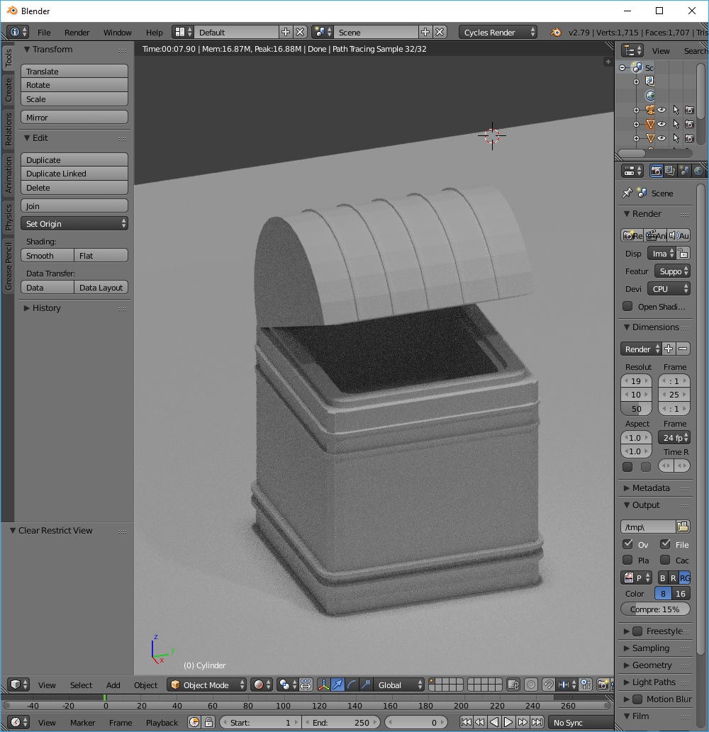
During this few weeks, I had been learning Blender (3D modeling Software) from scratch, it is really difficult to pick up, but i think the potential of Blender is far beyond what I need, so I will stick to learning this super useful program.
I’ve tried to follow a few tutorial and learn the basic of Blender from youtube, this was my first blender experience in building a 3D model.
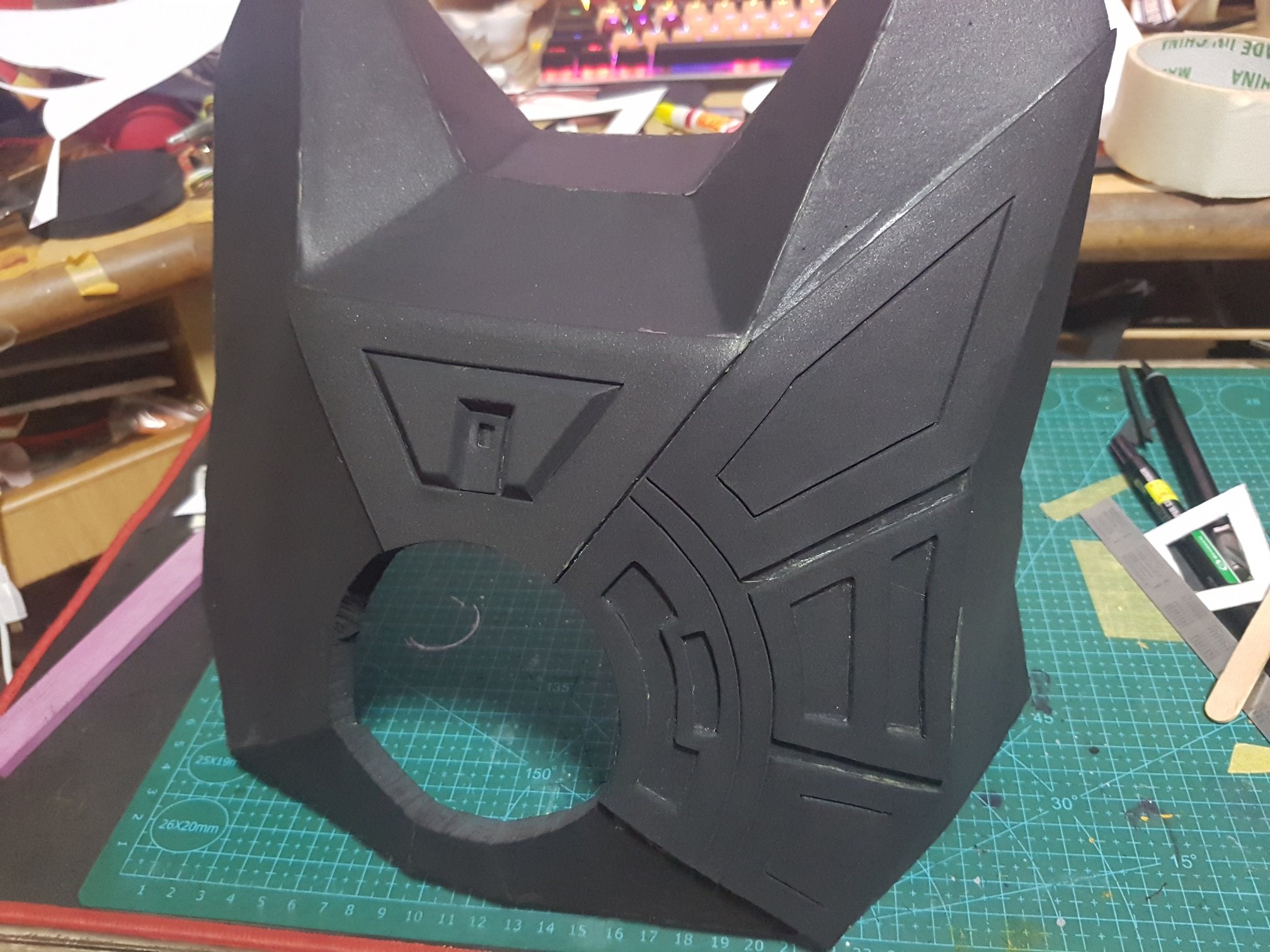
 I stated to learn by building chest as it got similar shape of what I want to produce, and after this, I used the skills i learnt from here and applied into the attempt of my R1 Robot.
 the overall shape of this is rather similar to the chest so it took a while to get used to this, however after building this, I realized that I don’t know how to make the top of the robot. So I progressed into another tutorial.

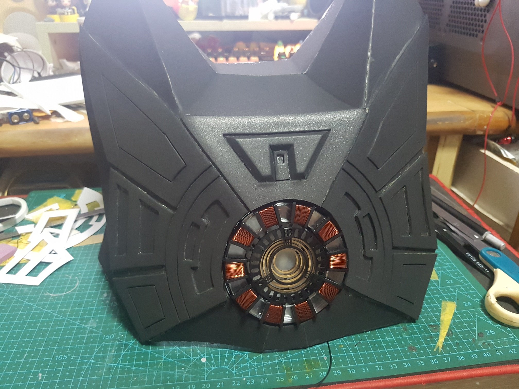
and this was the over shape that I made and I am pleased with it for a first timer effort, although it took me 2 days to reach here, after this, I continued to build the details at the side and front…
 Side view
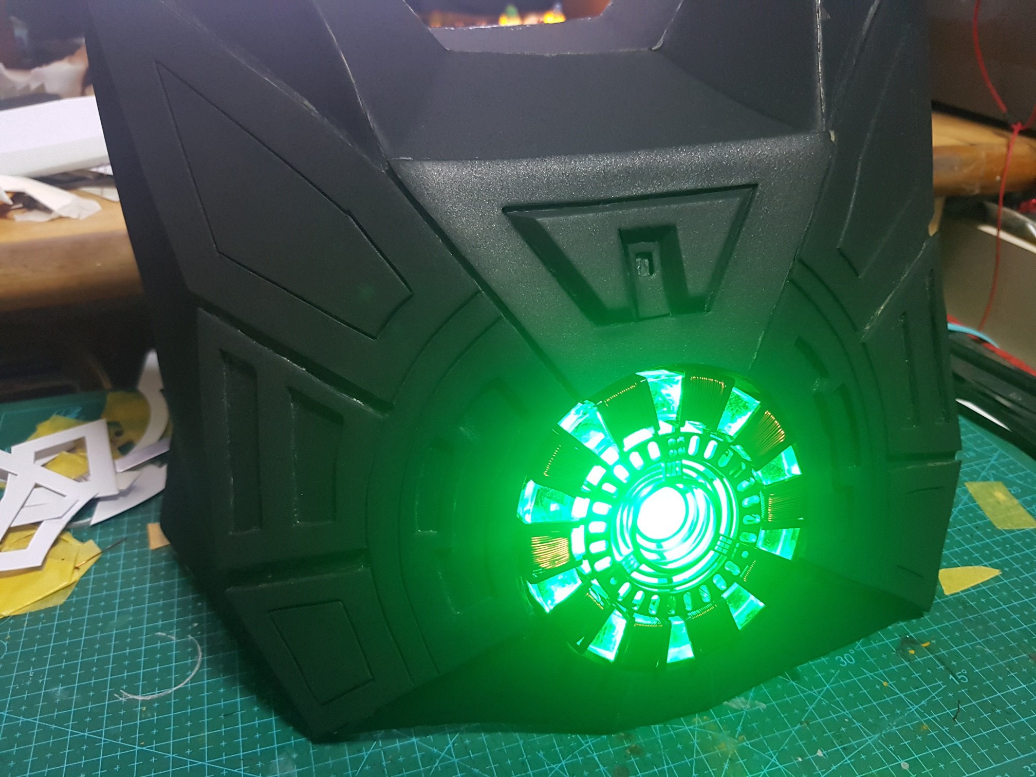
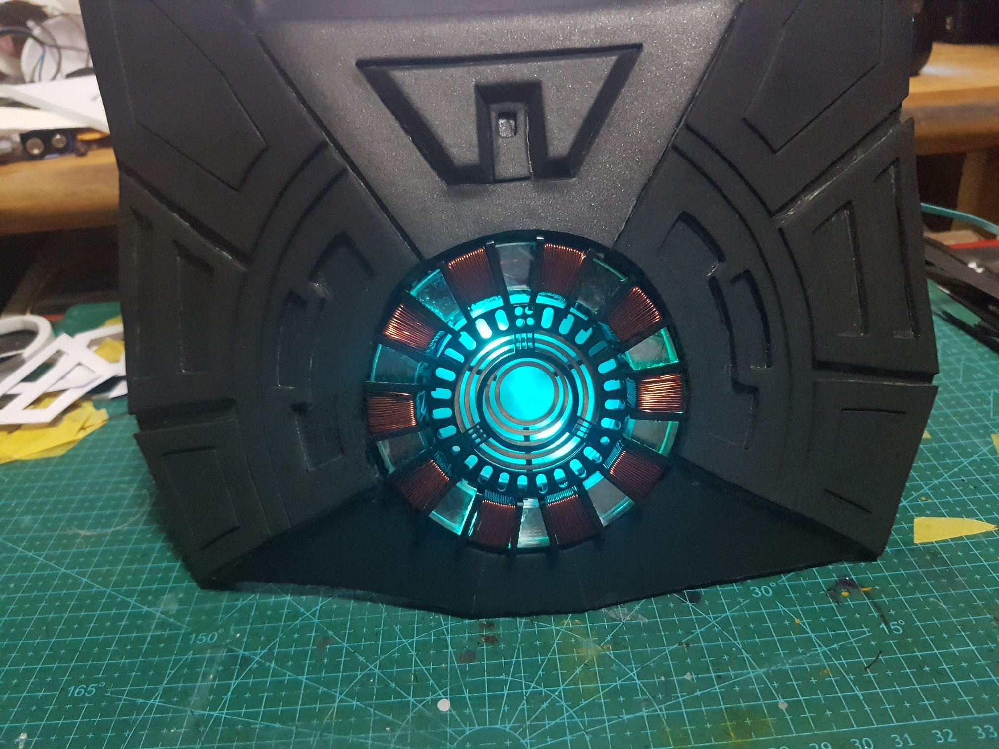
 Front view
and I decided to make it like a production poster so I rendered another isometric view to make it to looks legit for my presentation.

In blender, there is a animation function and I thought it would be really cool if I can learn it, so I went ahead to learn it from an online tutorial and produced this.

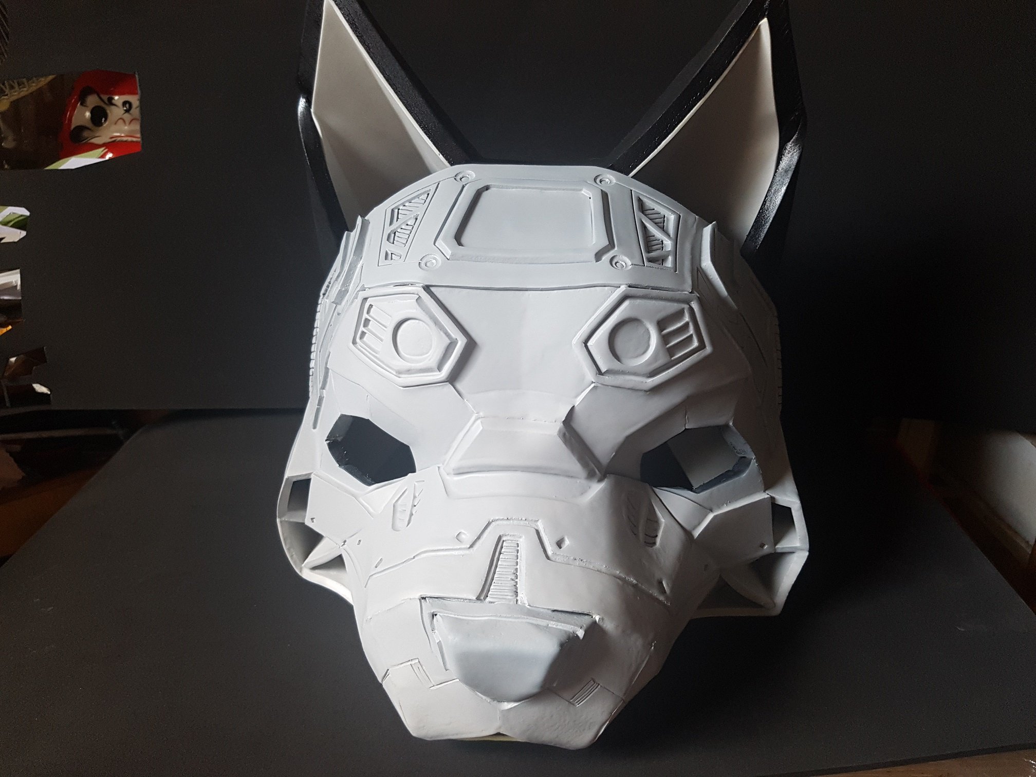
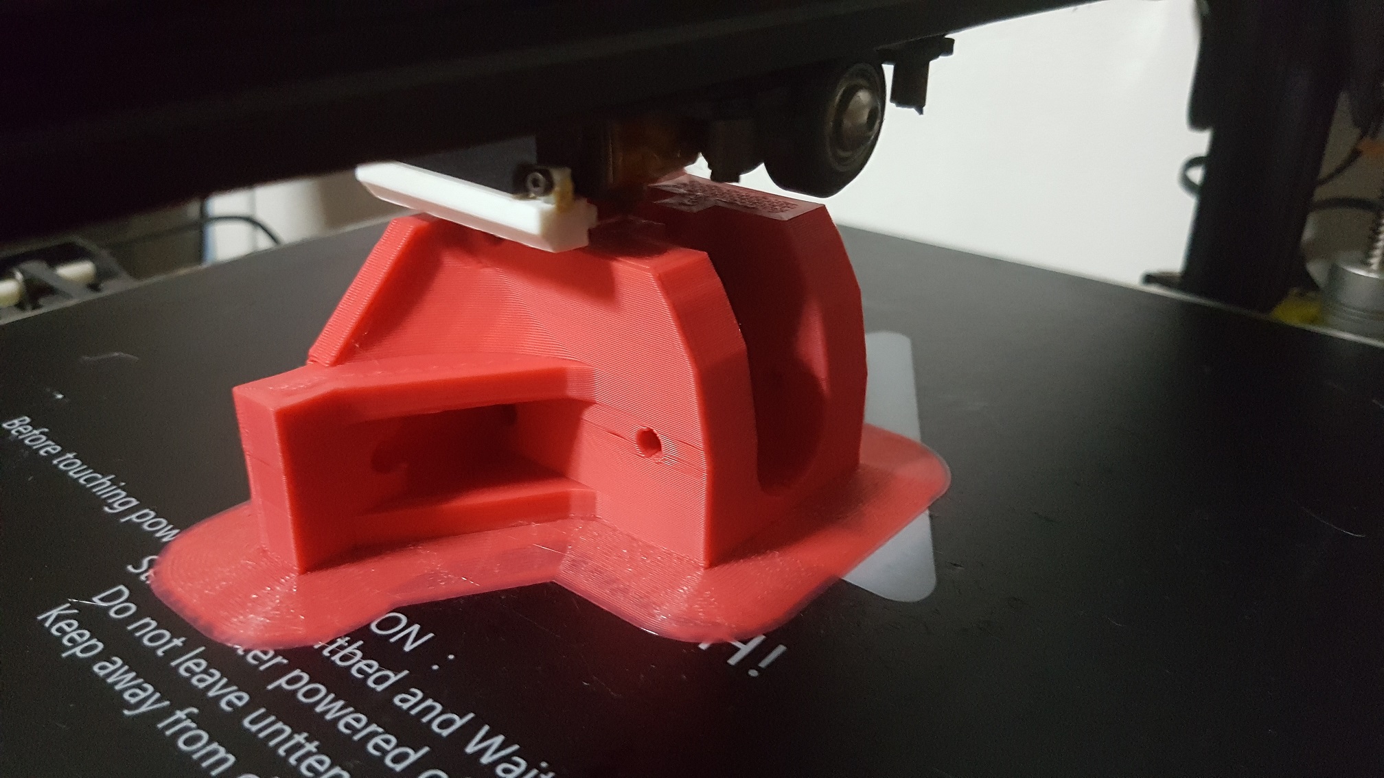
After I feel that this is good enough for the presentation, I tried to 3D print the model out, it was then then I realized that my model was full of mistakes and it only look good, in actual fact, the surface of the robot was really badly made. So the effort I made in this 3D model got to the furthest here, I will definitely be modeling everything again for the actual robots that I will be building for this FYP as this model doesn’t work, however this was a good learning experience for me and understand that I need to build the model’s surface properly.
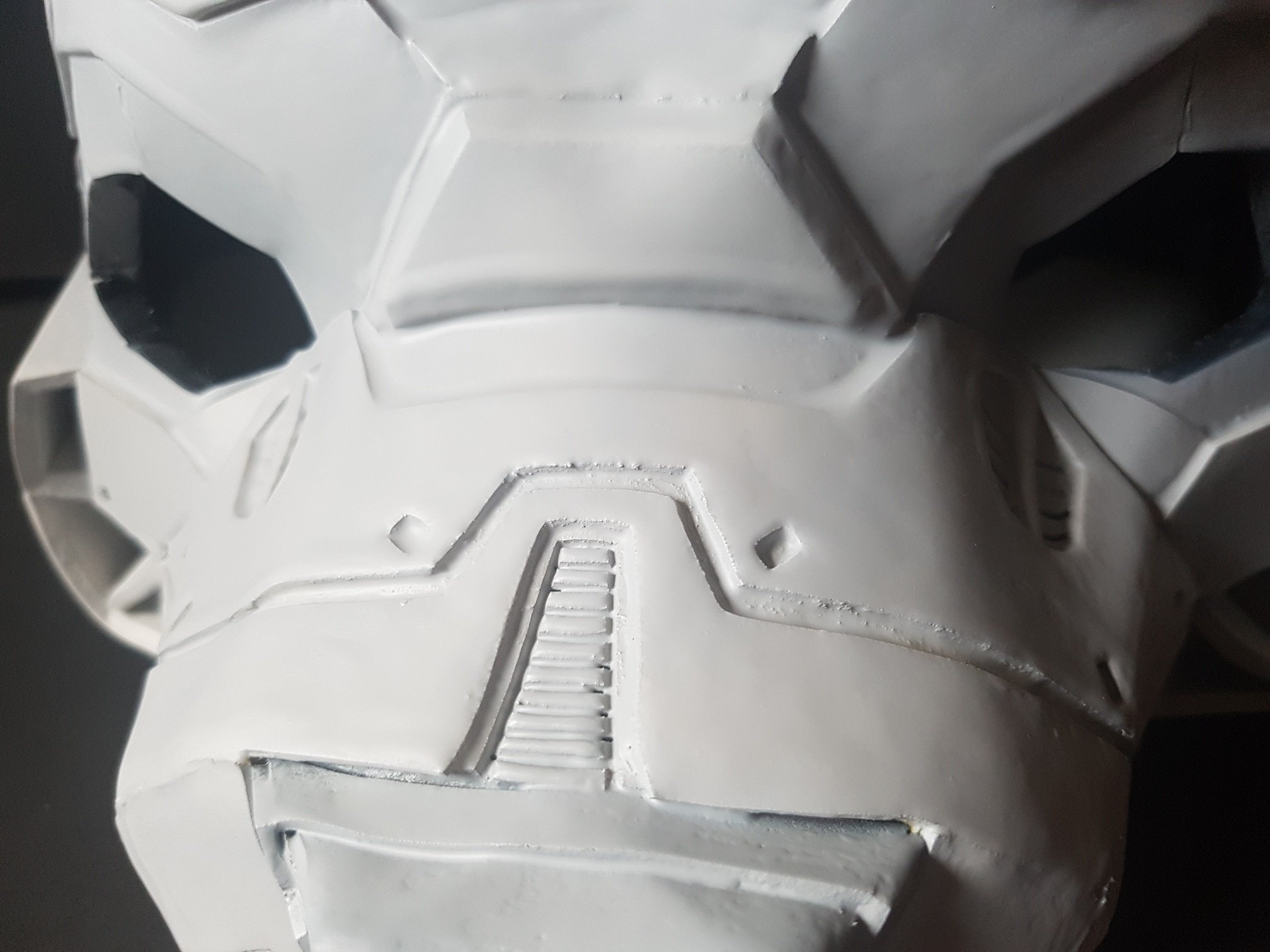
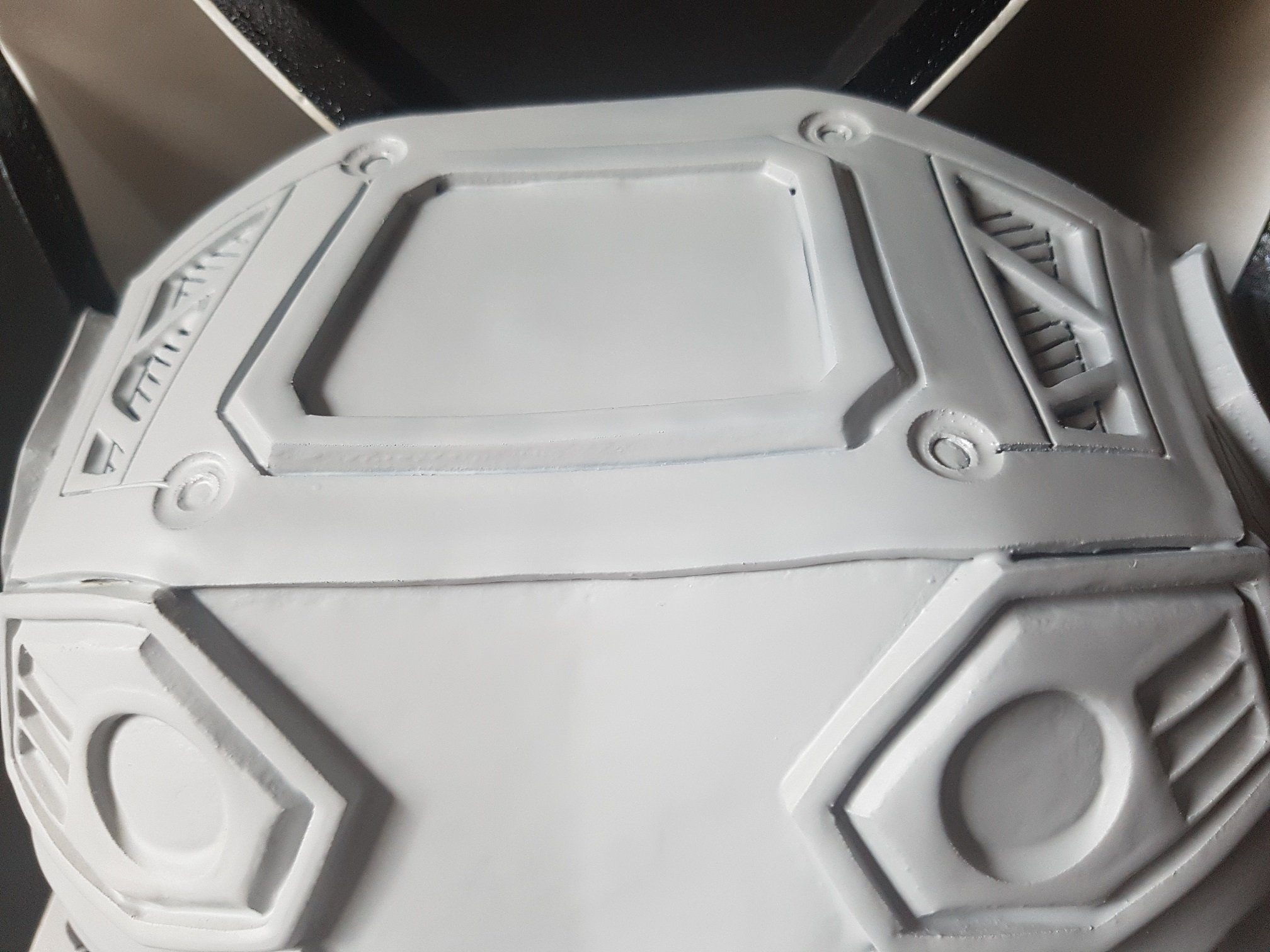
 the surface detail was not able to be printed due to the mistake I made during modeling, which creates an non solid surface and therefore not printable.

and then it was attached to a small remote control car for proof of concept to be used during the presentation.
now, the Crowd Favourite…..
Mr Gantt Chart!
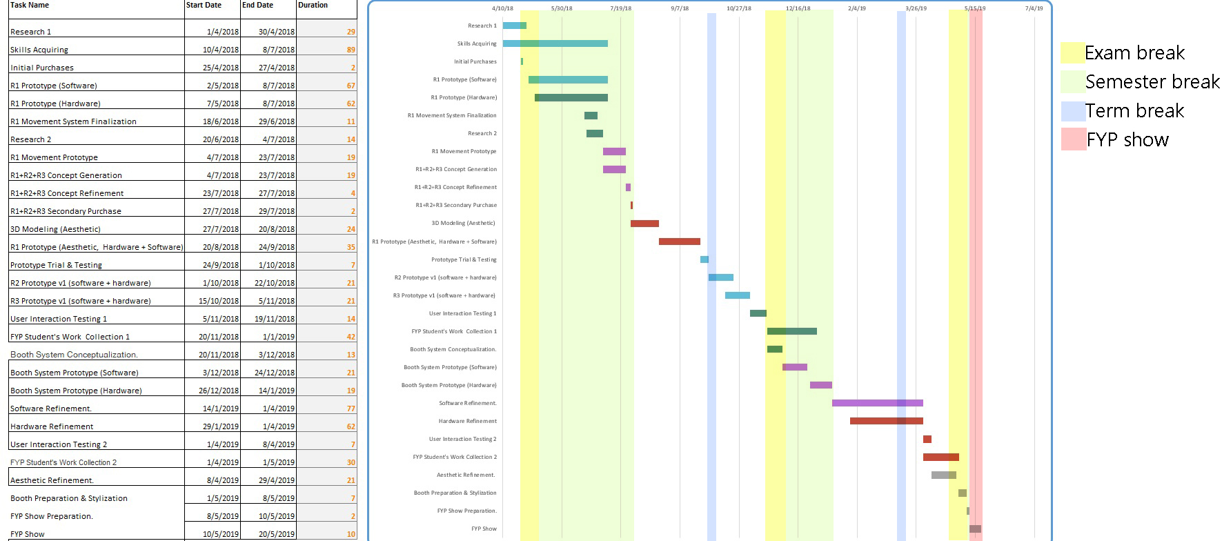
I started the Gantt chart at 1st of April 2018 as it was all research done till this point.
Within each task, there will be multiple small task which falls into the same category and I will explain them as well as a short description of what it is about here in this post.
Since my project will be physical+mechanical+ technological+ I need to get student’s FYP work early, it is really important to start the execution really early and throughout the holiday because building of the actual robot and troubleshooting the system will take quite some time, and I have to ask all FYP student to submit their work to me really early to make everything work.
Research 1 (1st -30th of April):
I think this is the most important factor of the project, good research done here will help me to reduce work greatly in the future.
Researches up till this point (16th April) – Similar Existing Products, potential parts, platforms for interaction, things I have to learn, Inspiration of artistic works, Parts price comparison, Target market and segmentation,
Skills Acquiring ( 10th April – 8th July):
There are many lacking knowledge and skills required for me to complete this project, like the list of things to learn, I need to learn a few of them to make sure that my system could work. Also, I need to pick-up 3D modelling skills as the knowledge I have now is insufficient, In the past few days, I’ve started to learn Blender, which is a free software for 3D modelling and is great for my project, still, time is needed to hone the skills hence the long period of time allocated to learn these skills.
Initial Purchases (25th April – 27 April):
One of the biggest way to save money is to purchase them from china, which will take weeks for the item to arrive, hence it is really important to buy research about the parts required and buy them early to use the least money for the best result. Also, initial purchases is set to 25th because I will be presenting on that day, if no major changes were made, I could only really consider what to buy after that.
R1 Prototype (Software and Hardware) (2nd May- 8th July):
This will go hand in hand with skills acquiring, as I need to have a goal of what exactly to learn, it is the best to do while learning and learn while doing. R1 is the first Robot that I will be building of the set of 3, which will be the bare-bone of the Robot basic functionality and act as a confirmation to the general systems and parts requires to build R2 and R3.
R1 Movement System Finalization (18th June – 29 June):
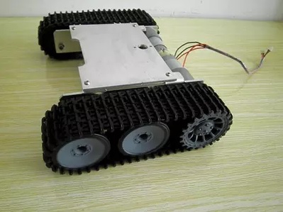
As movement is really difficult task to achieve while concerning about the safety of the people and booth, (It is really easy to make something move, but it is much harder to make it move while not destroying things.)
so I gave more time for me to think about how I will achieve this.
Research 2 ( 20th June – 4th July):
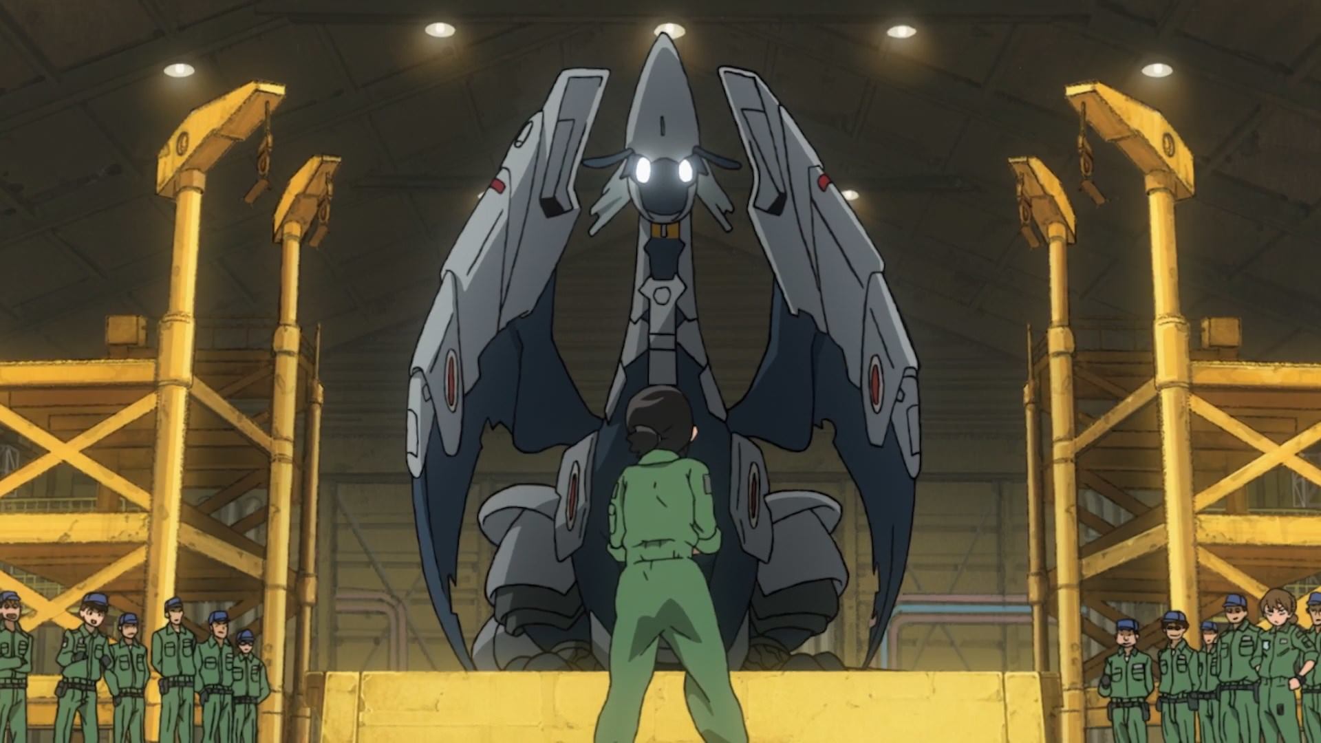
When I think of robots, I will think of Japan, maybe its just me since I was influenced by the robotic culture of Japan when I was young, so I will travel to Japan during this period to experience their advancement of robotics first hand. (Place which I will visit :National Museum of Emerging Science and Innovation (Miraikan), Unicorn Gundam in Odaiba, bot at Haneda Airport, Henn-na Hotel, Robot Restaurant (not sure about this).
R1 Movement Prototype (4th July-23rd July):
Start to prototype right after I am back from Japan from experiencing their robots and hopefully get to see how they works in Japan.
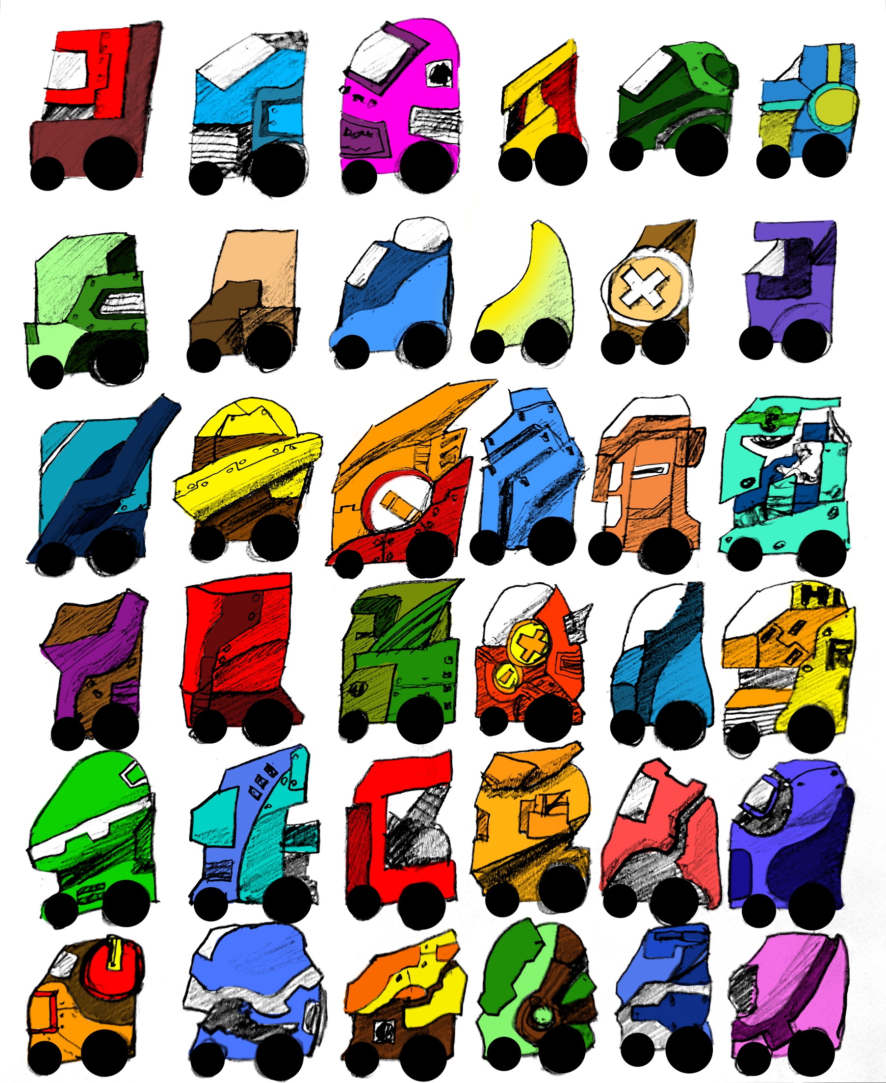
R1+R2+R3 Concept Generation and Refinement( 4th July -27th July):
Since by this point I’ve already understand what parts R1 requires and already have the measurement of parts and sizes like motors and screen size, I could think about exactly how each Robots will look like as they will look different and have different functionality.
R1+R2+R3 Secondary Purchase (27th July – 29th July):
Knowing what parts each robot needs, I could finally purchase the basic parts for R2 and R3, plus the add-on function for all 3 robots(each robots have different functionality so require different parts)
3D modeling(Aesthetics) (27th July – 20th August):
This will be the final appearance for all 3 robots, 3D modelling done in blender.
R1 Prototype(Aesthetics+ Software + Hardware) (20th August – 24th Sep):
3D printing of all R1 modeled parts, fix them together and make sure the software and hardware works, if it doesn’t, edit and reprint of the parts.
R1 Prototype Trial and Testing ( 24th Sep – 1st October):
when all parts work together, test the robots and system in a location to make sure everything work as expected and fine tune.
R2 and R3 Prototype V1 (Software and Hardware) ( 1st October – 5th Nov):
Since the primary component and system of R2 and R3 is the same as the already working R1, these 2 robots will require lesser time and the main portion of this 2 robot will be in 3D printing and executing the different function in them.
User Interaction Trail and Testing ( 5th Nov – 19th Nov):
Testing and making sure that there are no major bugs in the system, touchscreen and functionality works well.
FYP Student’s Work Collection 1 (20th Nov – 1st Dec):
At this time, all 3 Robot can roughly work and I’ve already document these robots, so instead of just verbally telling them I will help them in making their FYP better, It will be more stimulating if I show them a system which already work and ask them to prepare a document for this system for their own benefit. (it will not be easy to ask people to do extra work, so I need to make sure that I sell my Idea to them really early*That’s 1 semester before the end of FYP* by making these robots cool and they will be losing out if their work is not in the systems.) Also, at this point they don’t have to send me any work and it is already the semester break so they have some time to think about what they want to prepare for the systems.
Booth System Conceptualization.( 20th Nov – 3rd Dec):
By this time, I should have the system of the robots working and I need to incorporate that into booth for our FYP, and this will probably be the time which we will know where our FYP will take place(in school or in public) and this will change how the booth system drastically, so it will be better to place this at the end of semester break.
Booth System Prototype (Software + Hardware) (3rd Dec – 14th Jan):
after the conceptualization, prototype will come next and I hope to have this done before the start of semester so that I will have the fully working prototype done and having the whole semester to polish my work, troubleshoot and bug fix.
Software and hardware Refinement (14th Jan – 1st April):
Software and Hardware refinement will take up most of the time as the real problem will usually emerge at this point of time where some shortcoming of the project will be apparent, also, there might be good suggestion/advice by people along the way and this will be the time to incorporate these wonderful suggestion into the project.
User Interaction Testing 2(1st April – 8th April):
Testing of the final system, to make sure all parts and component work as it should. if problem found, atleast there are time to replace these components.
FYP Student’s Work Collection 2( 1st April – 1st May):
The final collection of (Hopefully) all of the student’s work and adding them to the system once it’s collected. At the very least, there will be the basic information of every student which is uploaded to the FYP website.
Aesthetic Refinement( 8th April – 29th April):
The polishing and painting of the 3 robots and making of props/items for the booth. (when all software and hardware is working)
Booth Preparation & Stylization (1st May – 8th May):
Production of prints for booth, name cards/postcards and such.
FYP Show Preparation. (8th May – 10th May):
The actual preparation of the Booth and to bring the robots down to the exhibition area and set everything them up.
FYP SHOW( 10th May- 20th May):
Make sure the show runs smoothly, on-site repair if needed.
CATEGORY
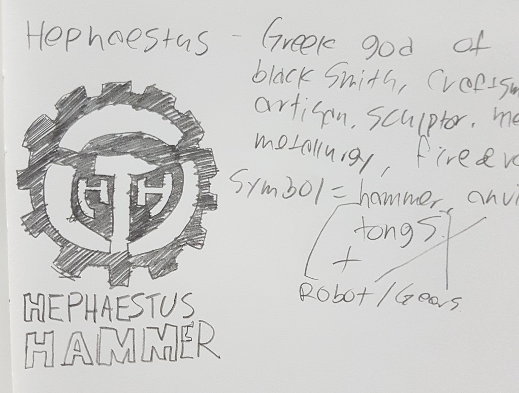
FYP IDEA: To create a system which will benefit the FYP students and gives the guest an improved visiting experience.
researches,
component (pricing, compatibility, functionality, component sponsorship(especially for battery))
softwares (research for platform + udemy courses)
movement (sensors, moving system + hardware) (main moving calculation should be done on the booth computer and transmit over to robots due to power issue, (more computation power it runs, more power it will draw)


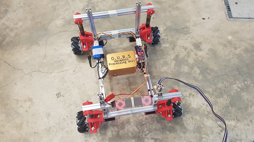


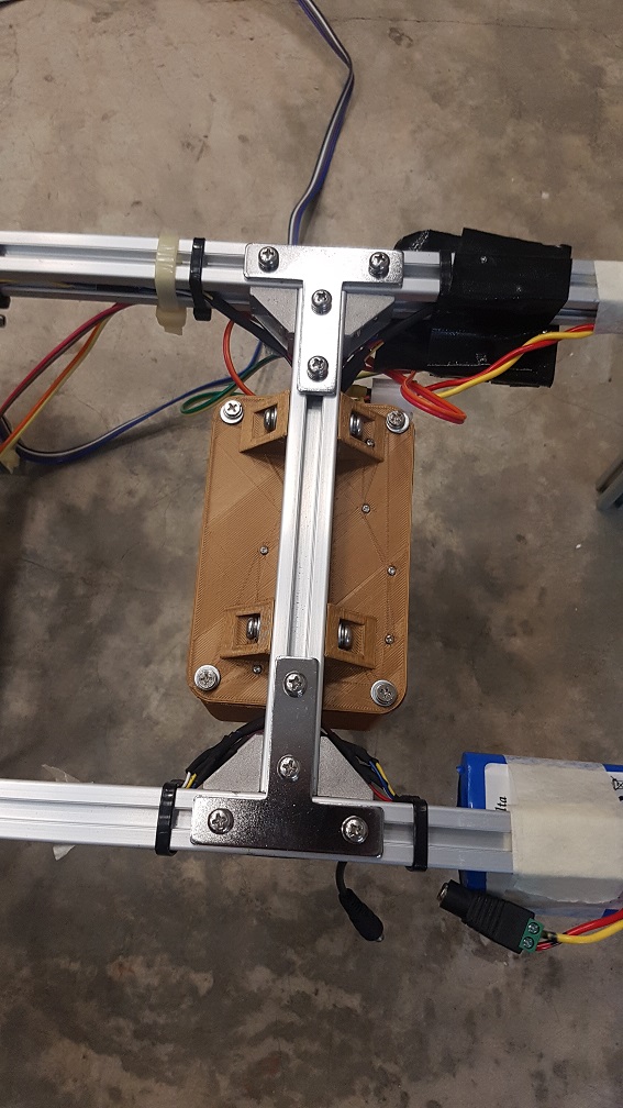

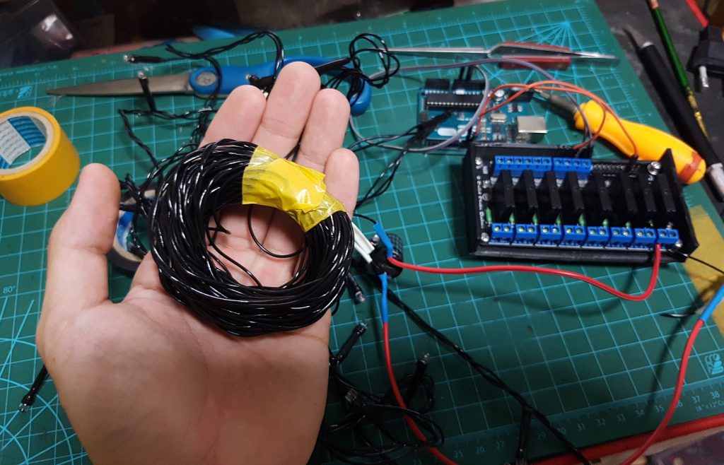
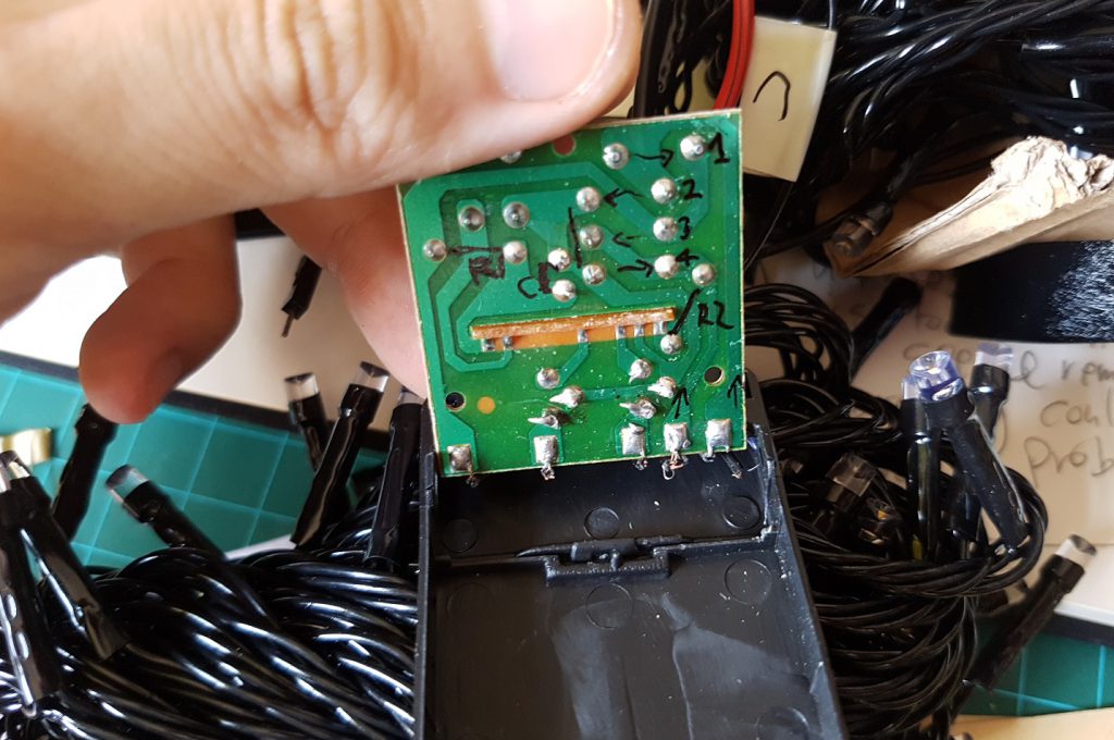
 To experiment with speed and delay of Lattepanda with unity to control arduino, which is not bad!
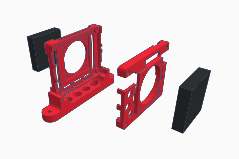


 I stated to learn by building chest as it got similar shape of what I want to produce, and after this, I used the skills i learnt from here and applied into the attempt of my R1 Robot.
 the overall shape of this is rather similar to the chest so it took a while to get used to this, however after building this, I realized that I don’t know how to make the top of the robot. So I
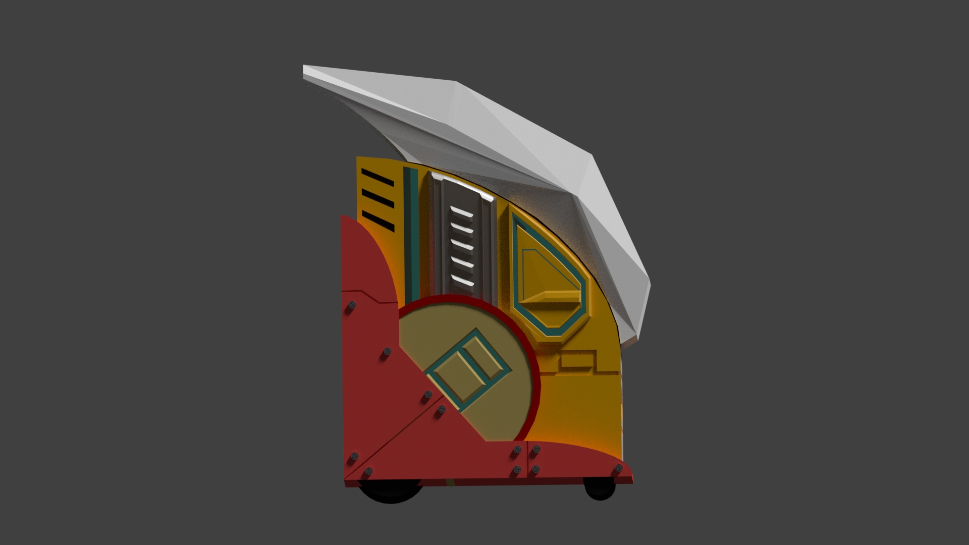 Side view
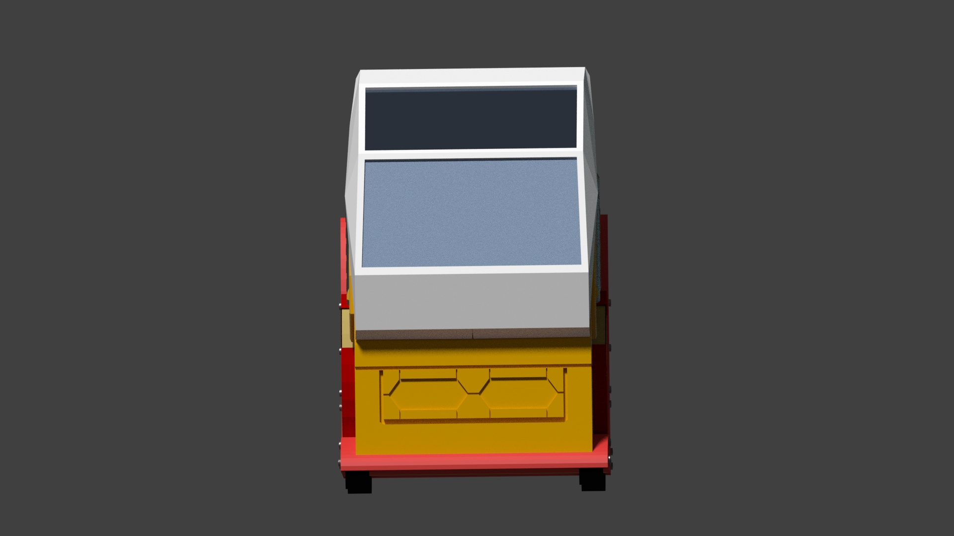 Front view
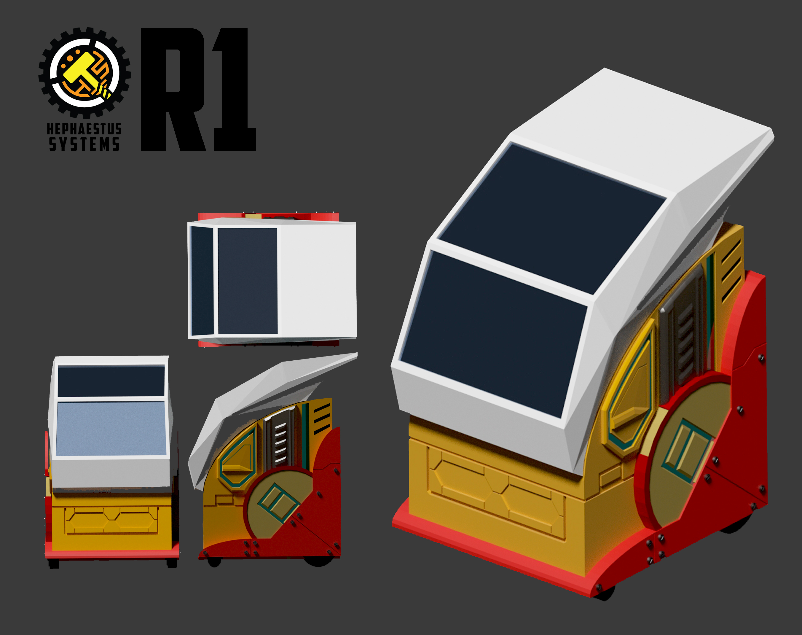
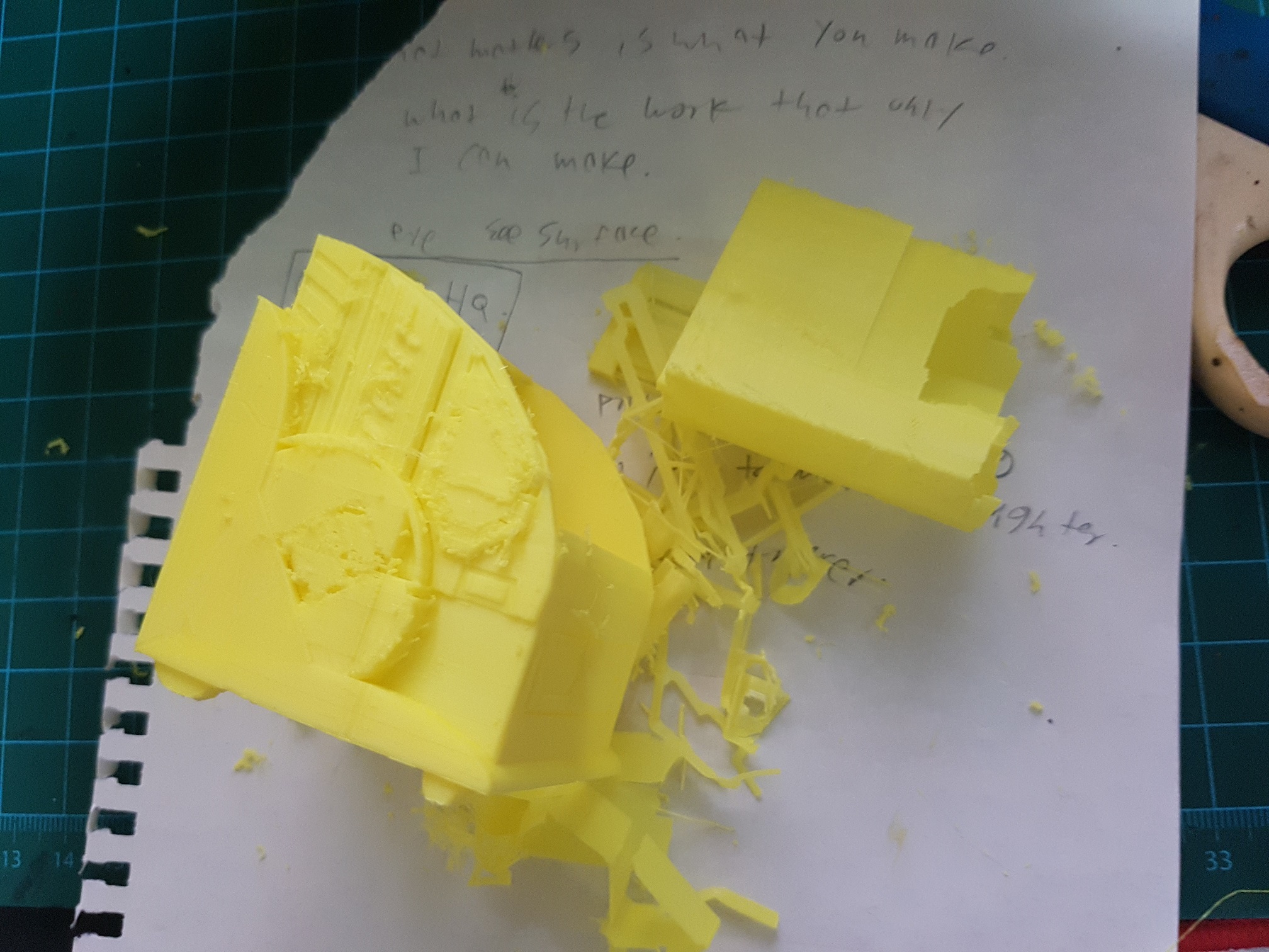 the surface detail was not able to be printed due to the mistake I made during modeling, which creates an non solid surface and therefore not printable.


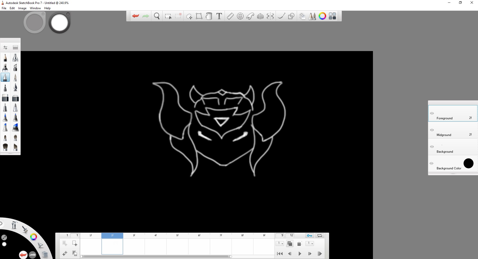
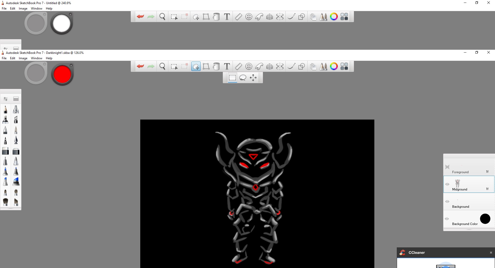
 and then I digitally coloured it.
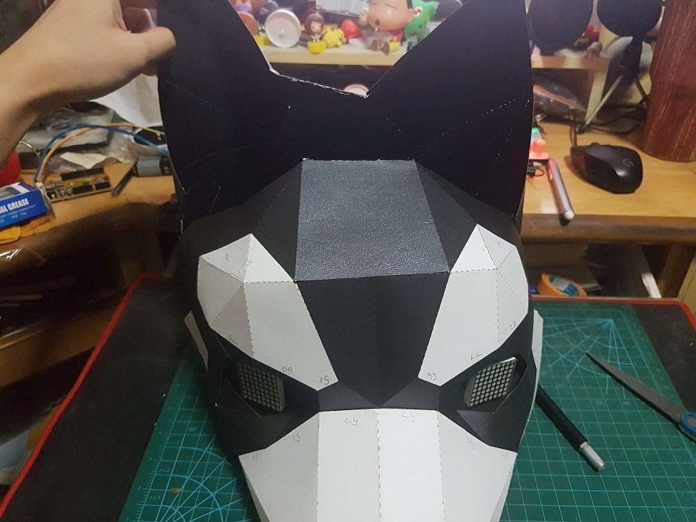
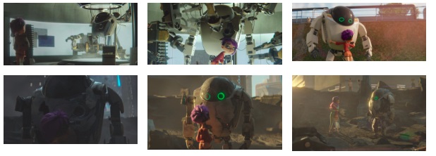
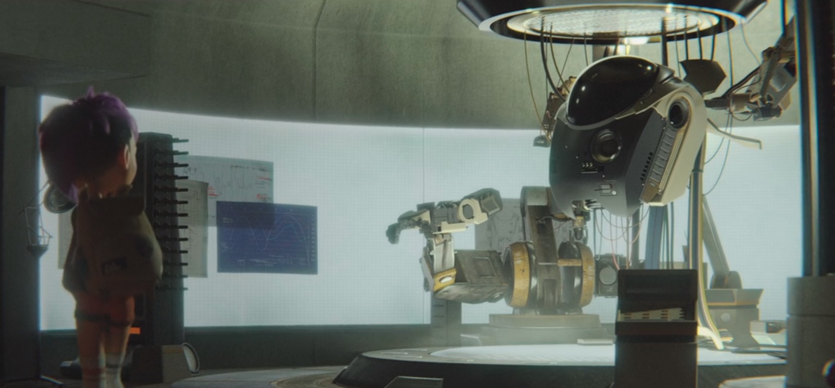
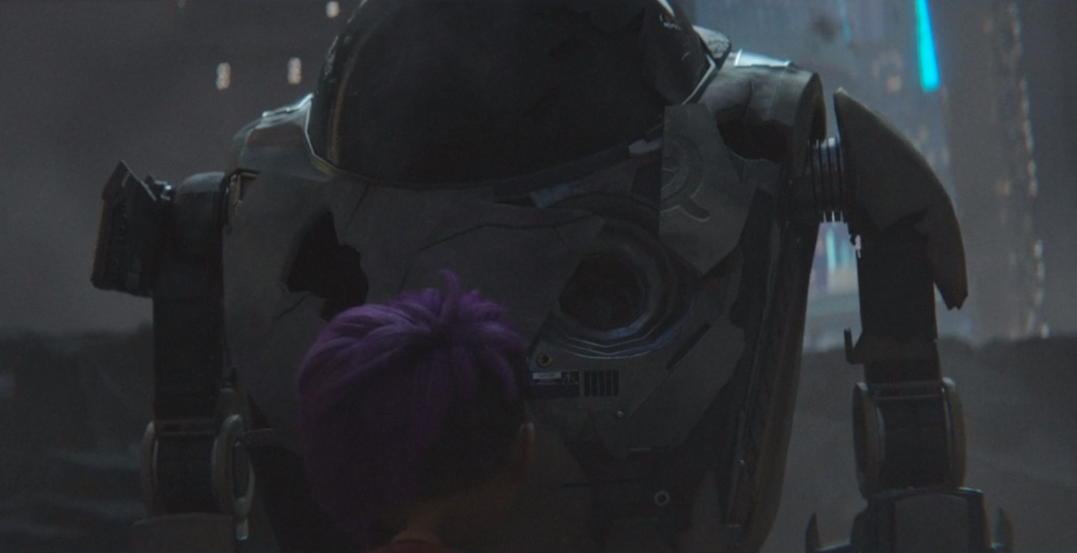
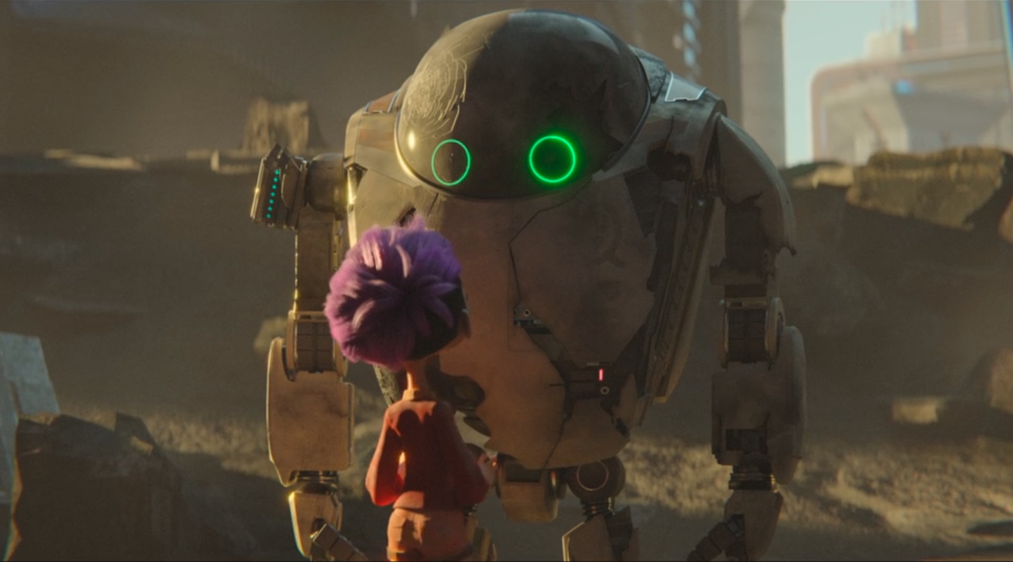
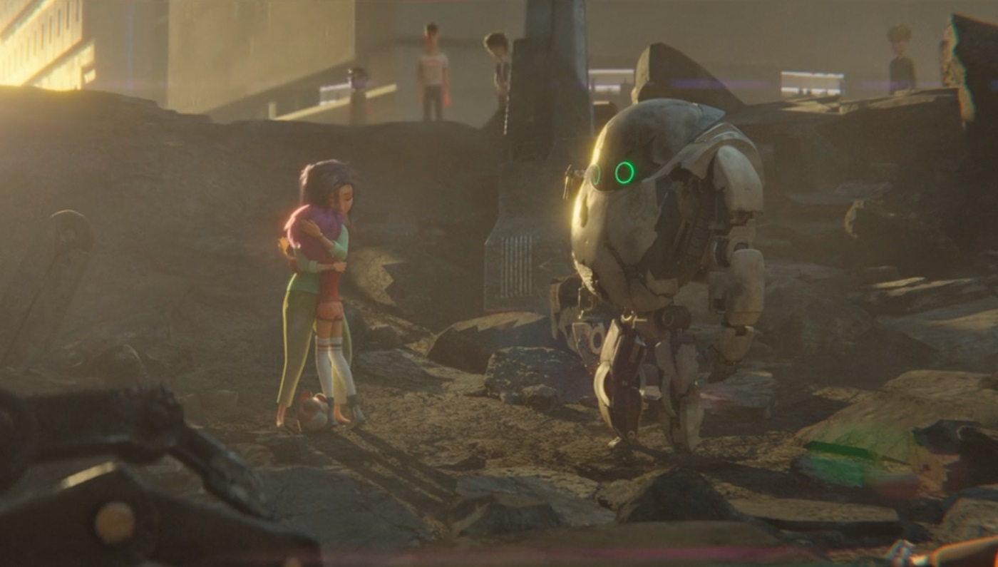
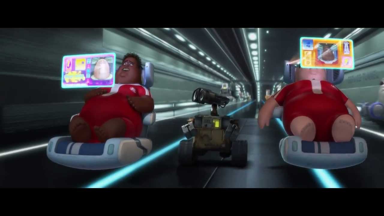
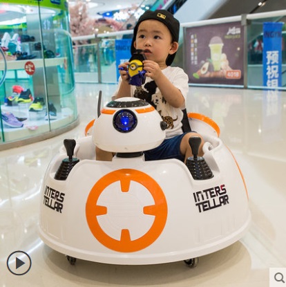
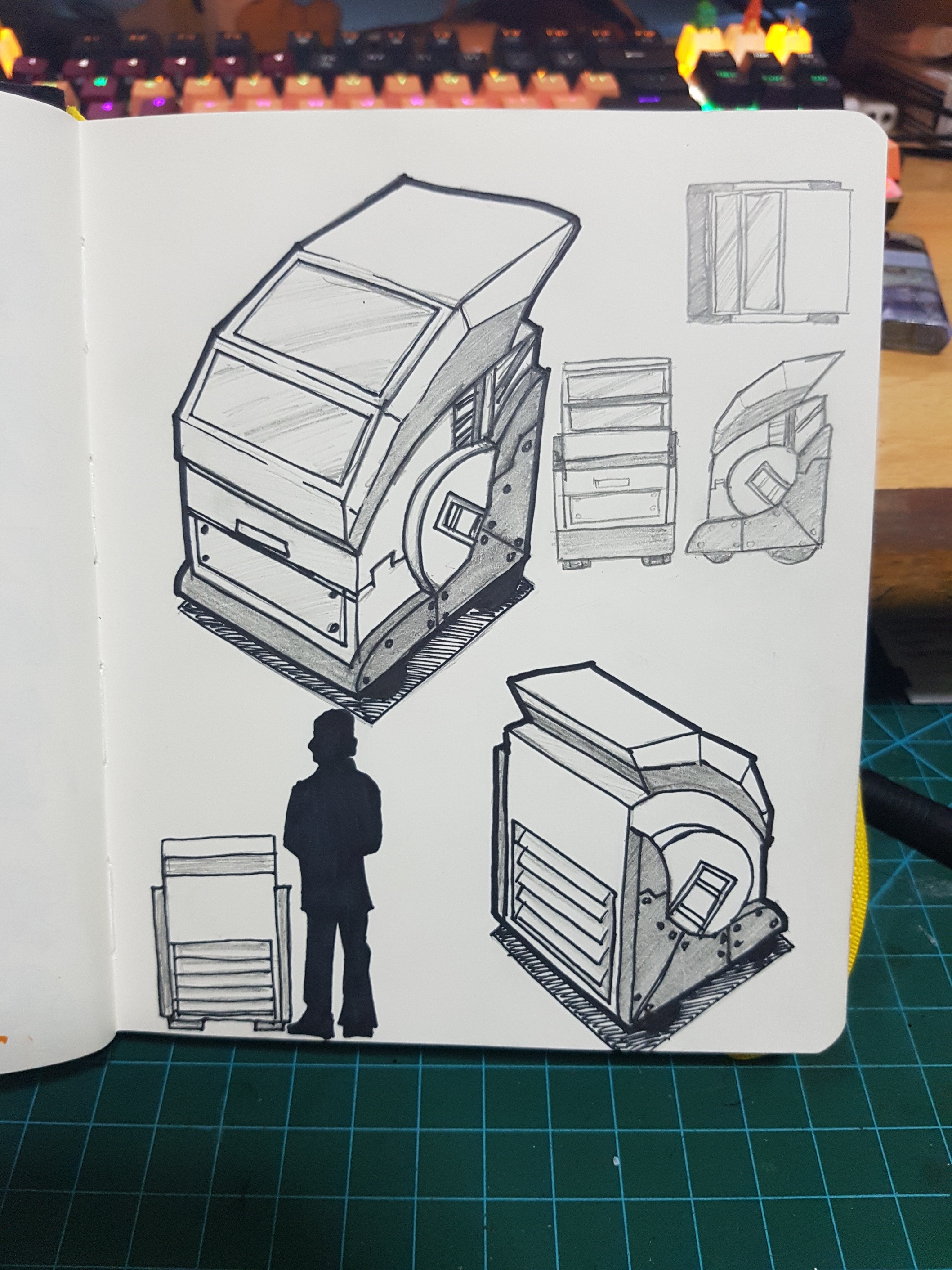 This will be the general appearance and sizing of the robot and I will probably change it drastically along the way, however I would like to use this as an example to explain about my project. Without this drawing, I normally explain to people by saying “a trash bin alike robot that move around” and by trash bin, I simply meant no limbs and I think it will be rather misleading.
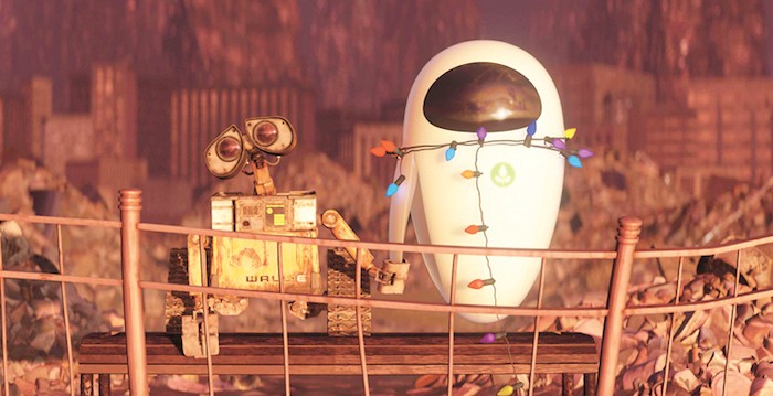
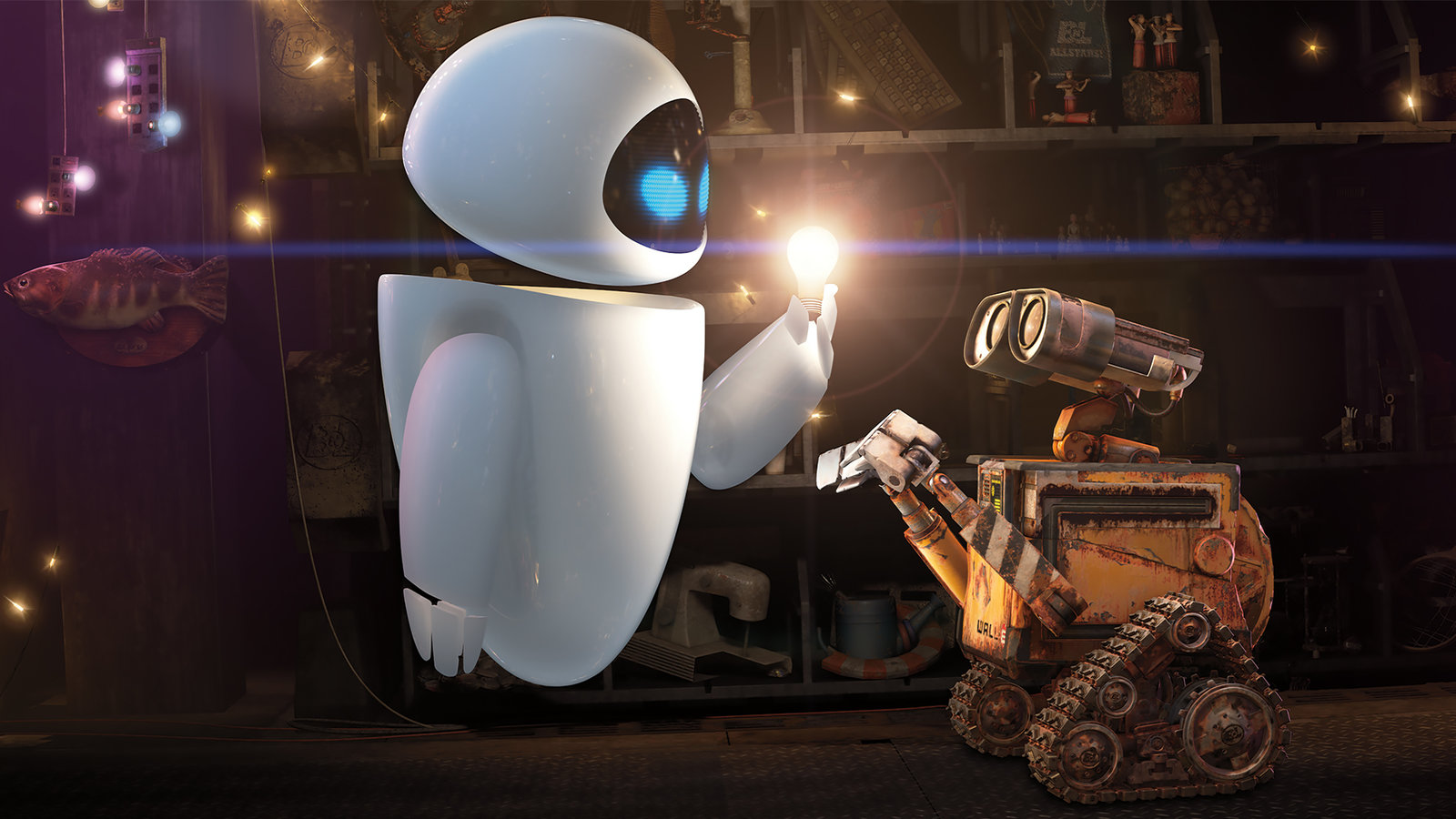
 White humanoid with round, smooth features, almost no surface detailing and no styling, just a LED eye or sometimes a screen on its chest. Nope, I don’t want to do it like this.


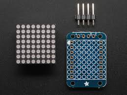 https://www.adafruit.com/product/870
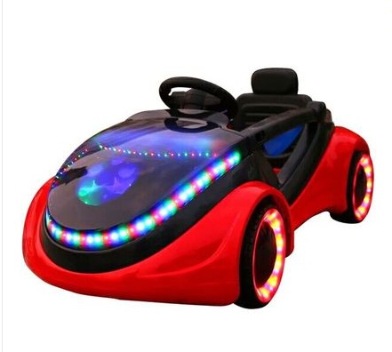
