After a long time of not updating, I’ve started to built the actual head for the robot using EVA foam, which was my first time using it. The reason I am using EVA foam is that it is lightweight yet firm, easy to cut and form into shapes, and the joining of parts only requires contact glue (other glue will suffice but contact glue gives a better stick). Plus, I know that I will be building as and conceptualizing at the same time as I do not have any blueprint, every little details on the robot will be an impromptu decision I make during the building process, so low price of the EVA foam will allow me to work more freely so that I do not have to be afraid of making mistake and paying a huge sum of money on it.
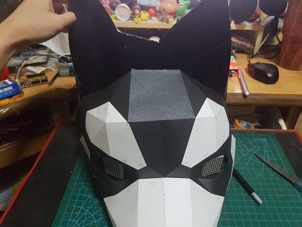
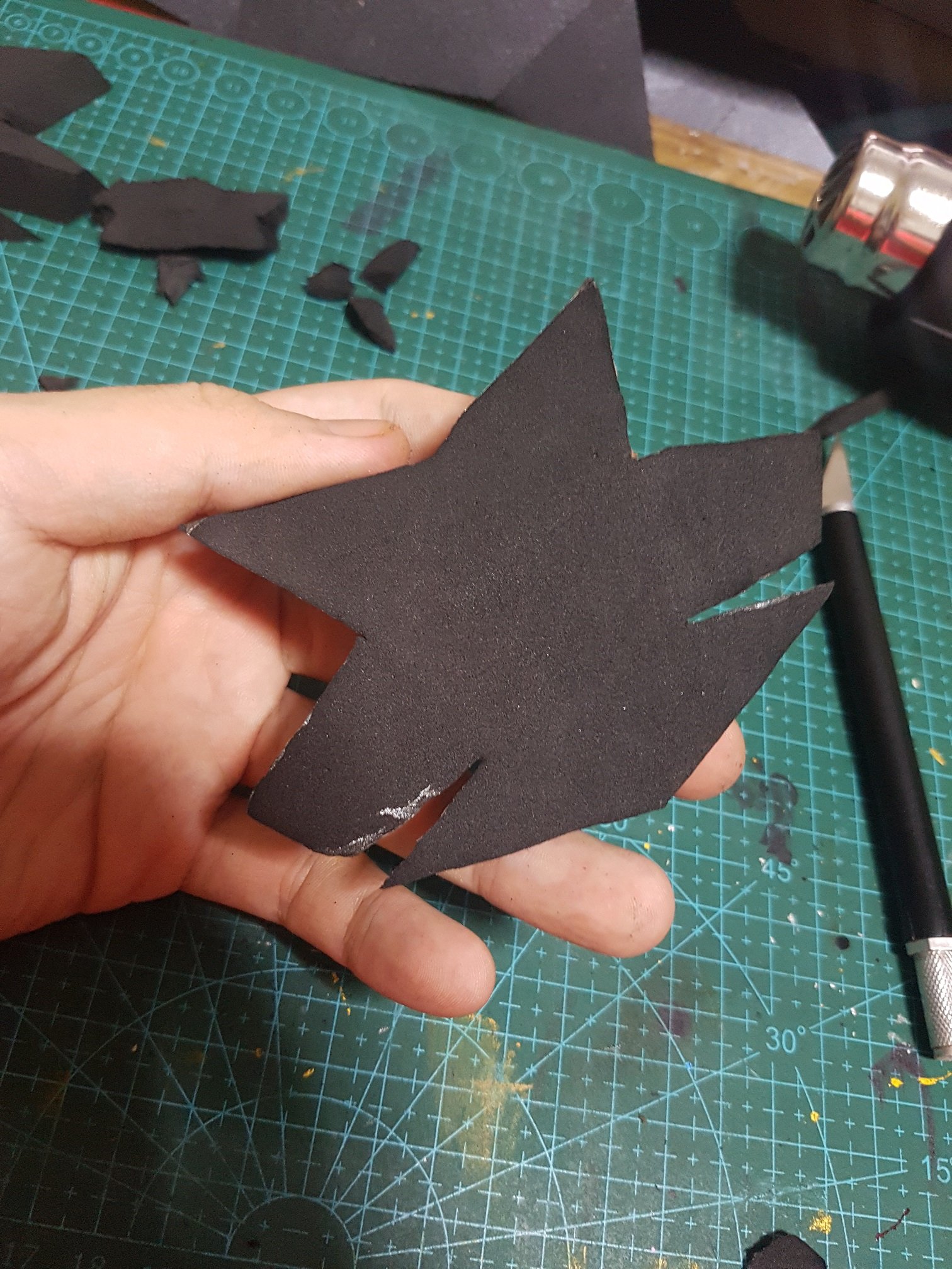
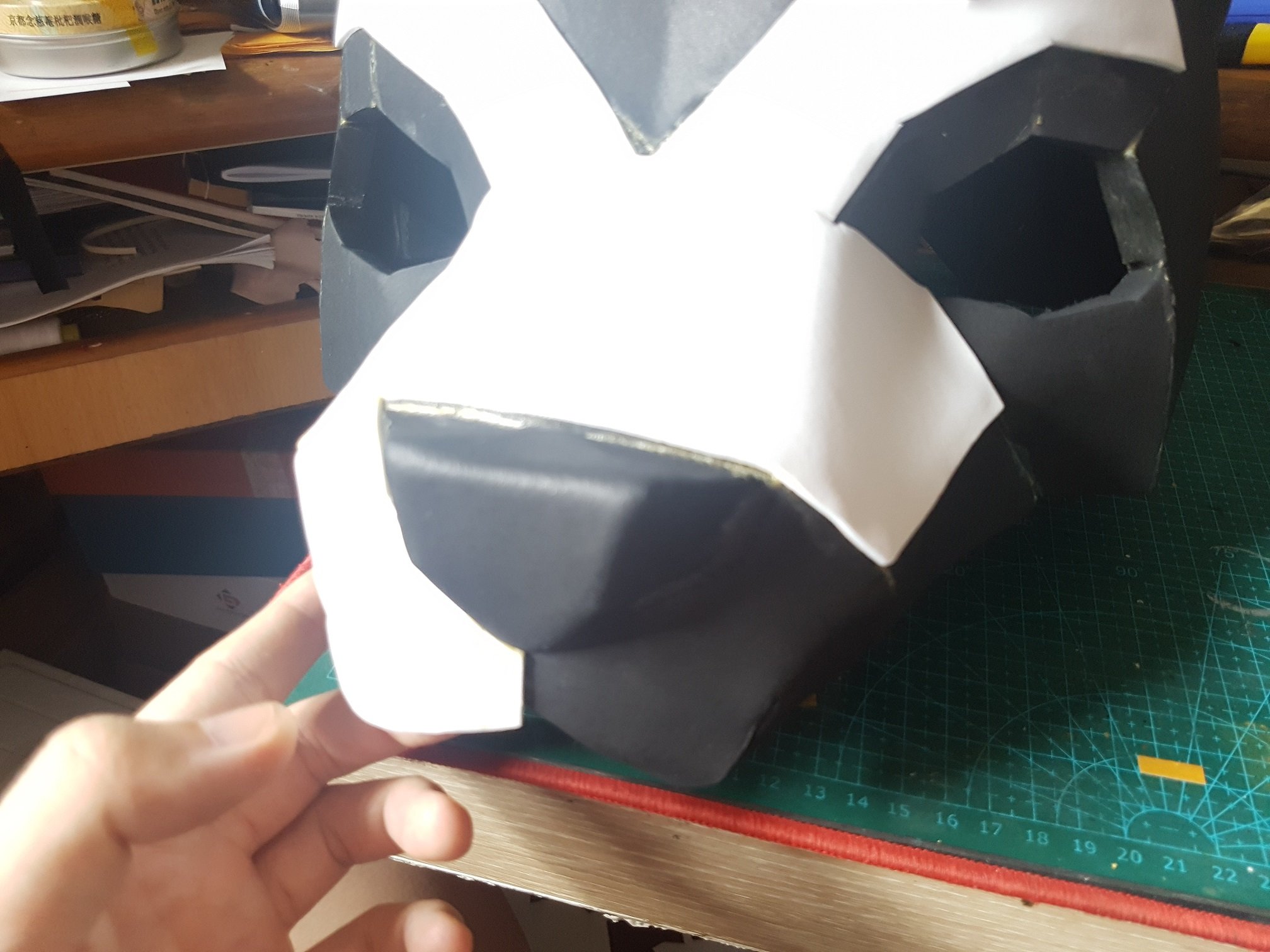
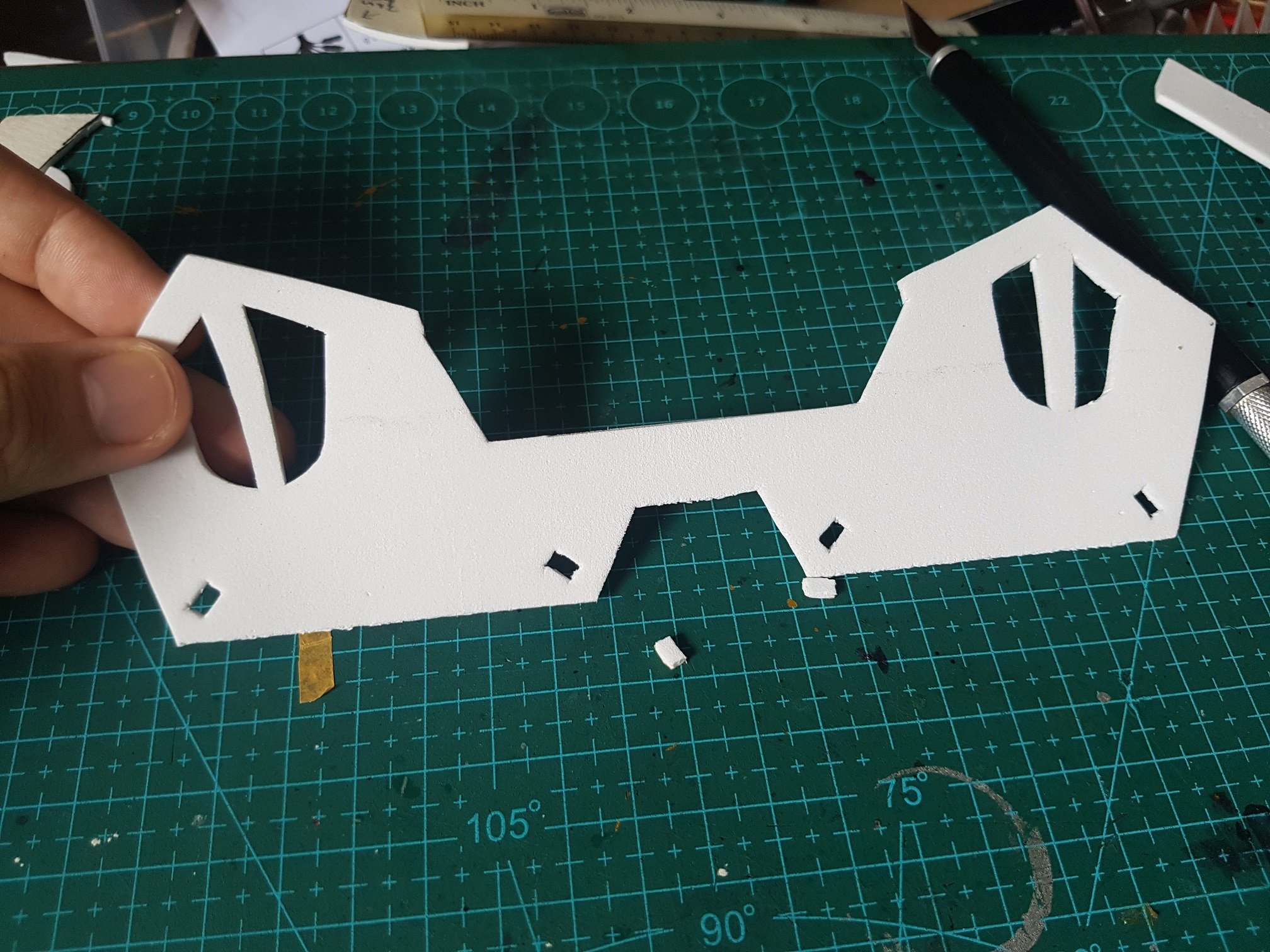
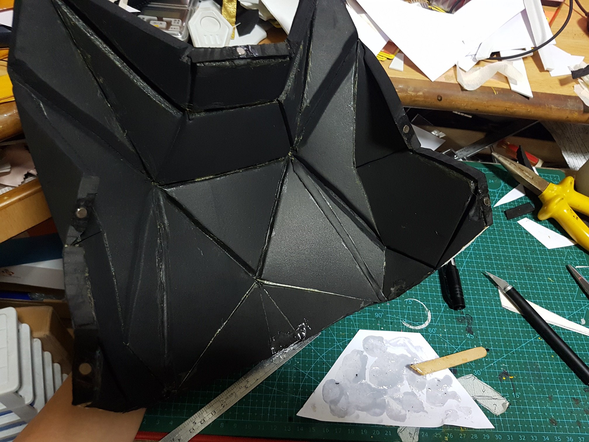
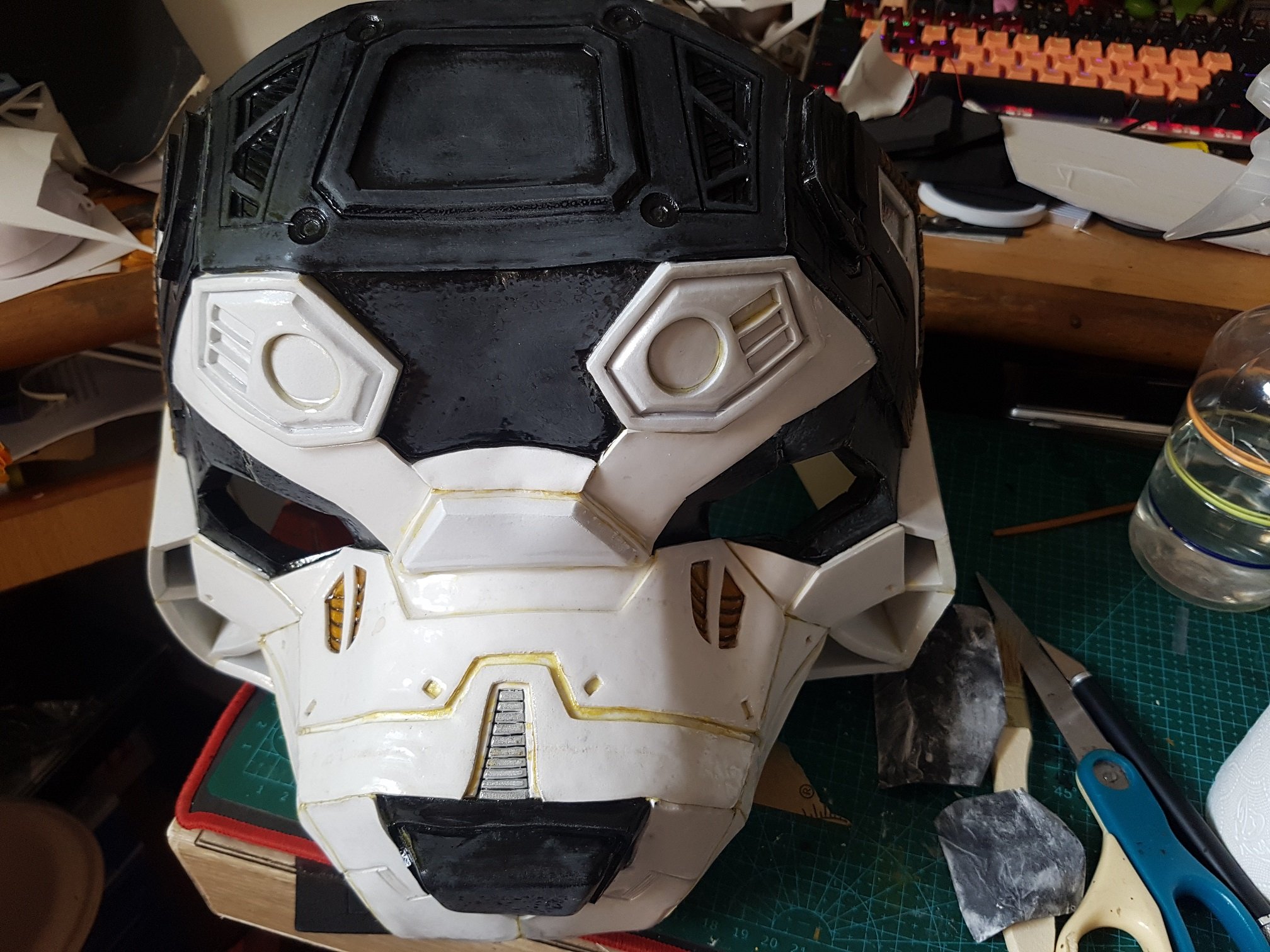
To start it off, I converted the paper Husky head into EVA model with 10mm thick EVA as a base layer.
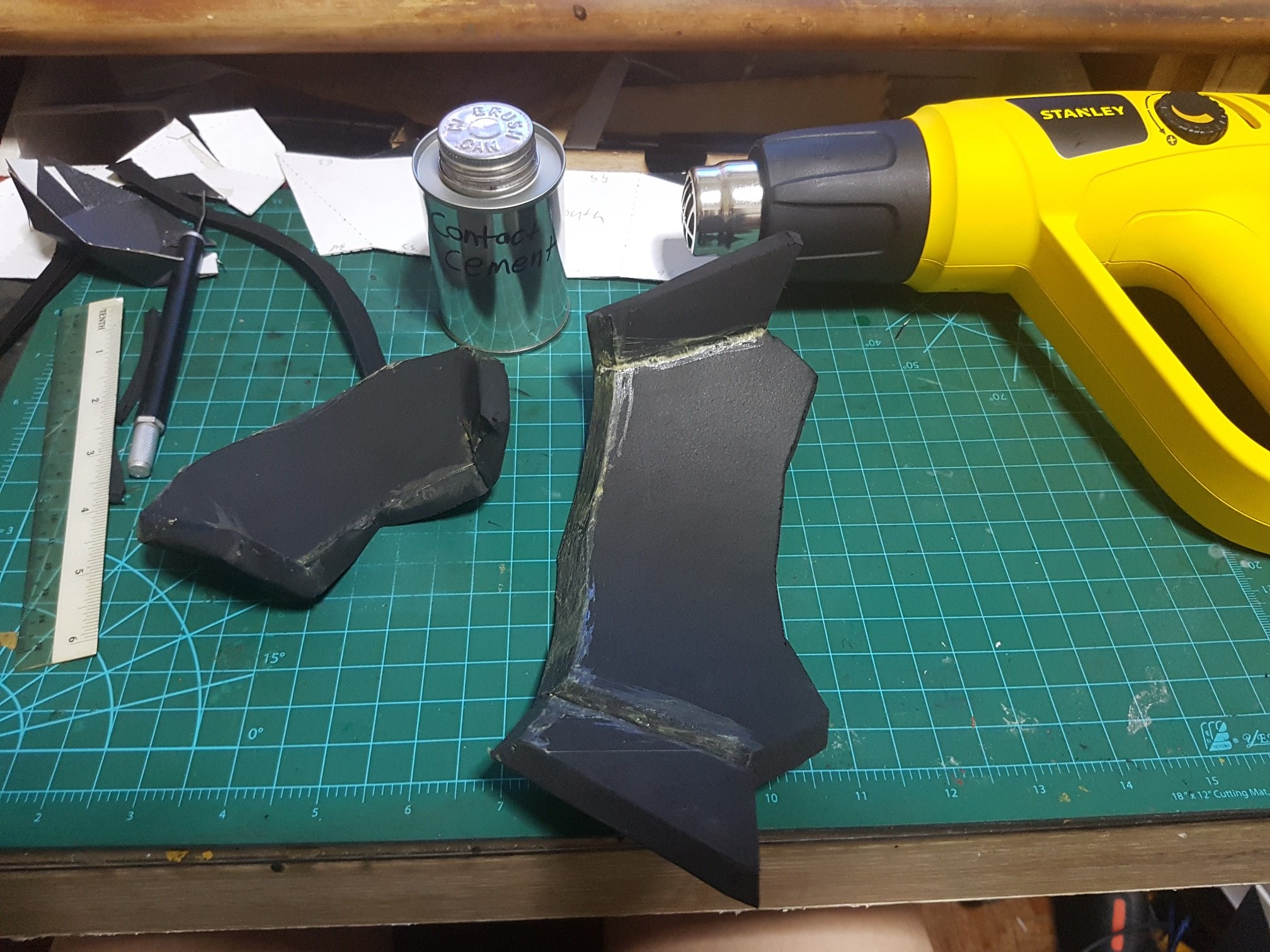
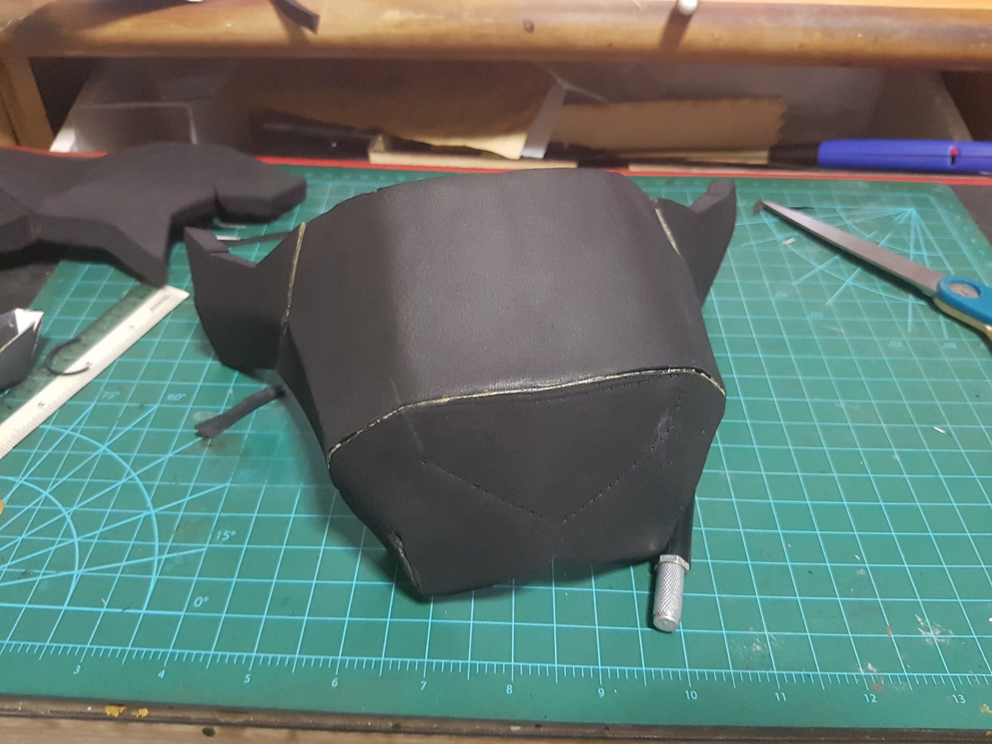
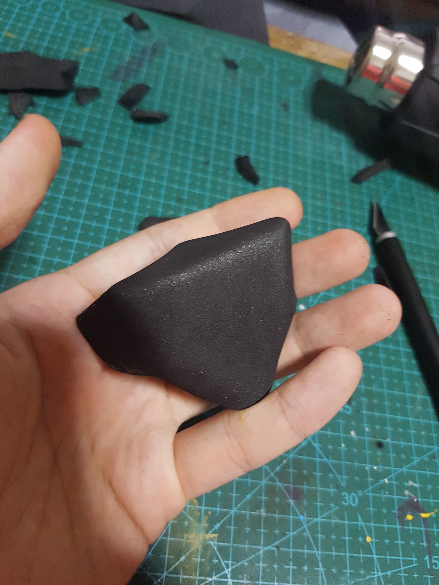
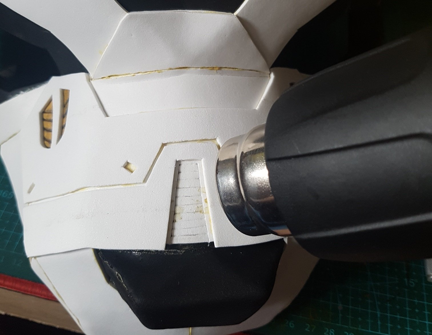
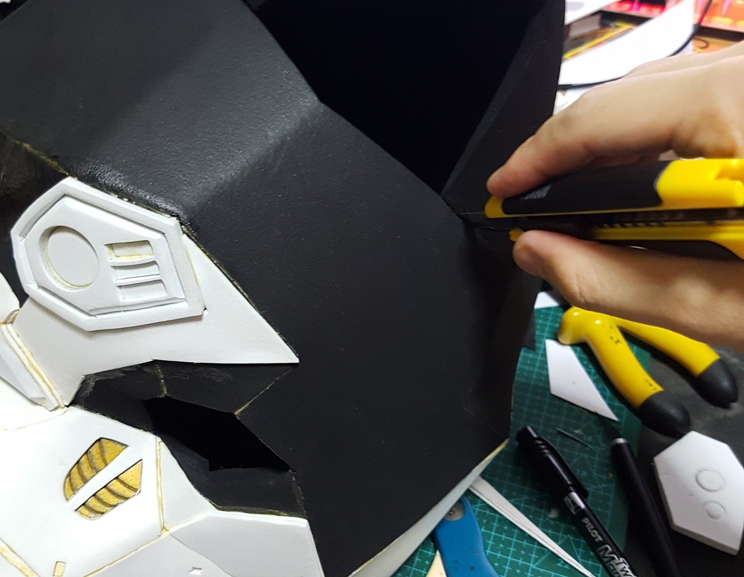
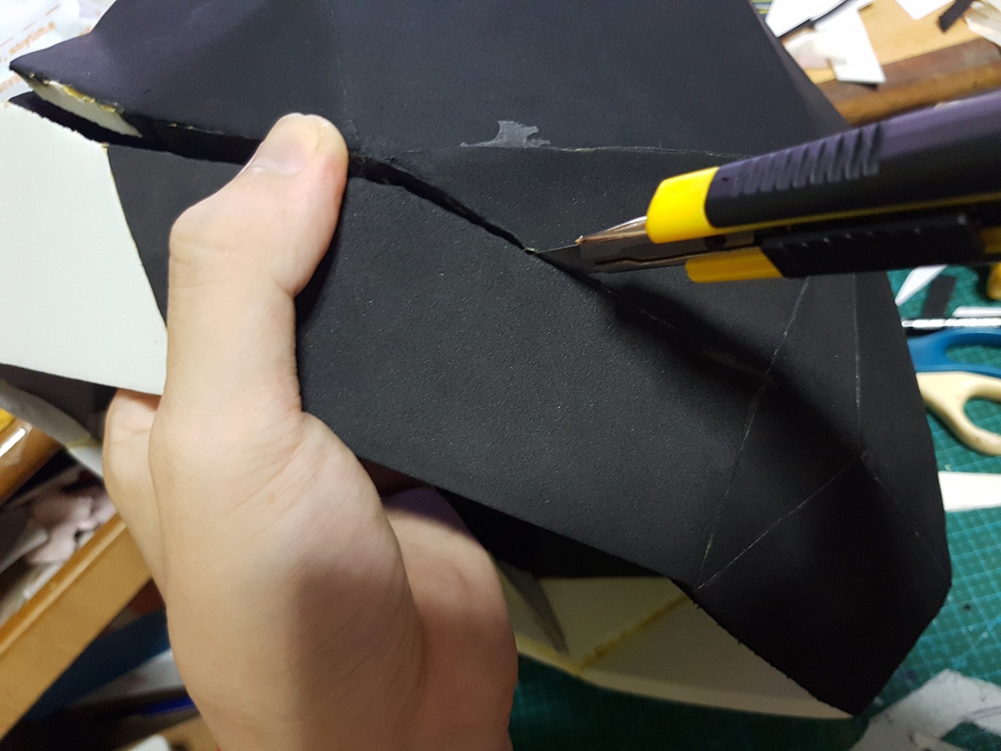
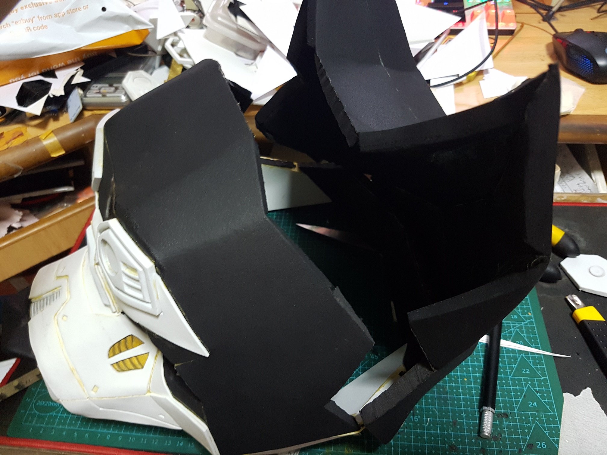
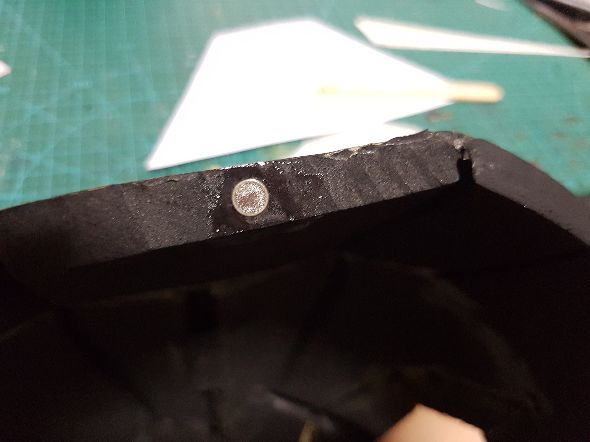
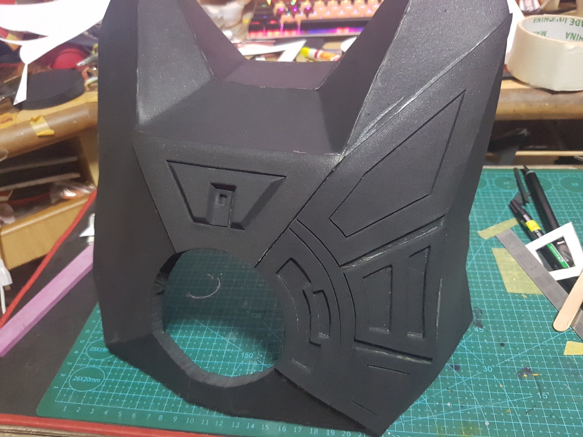
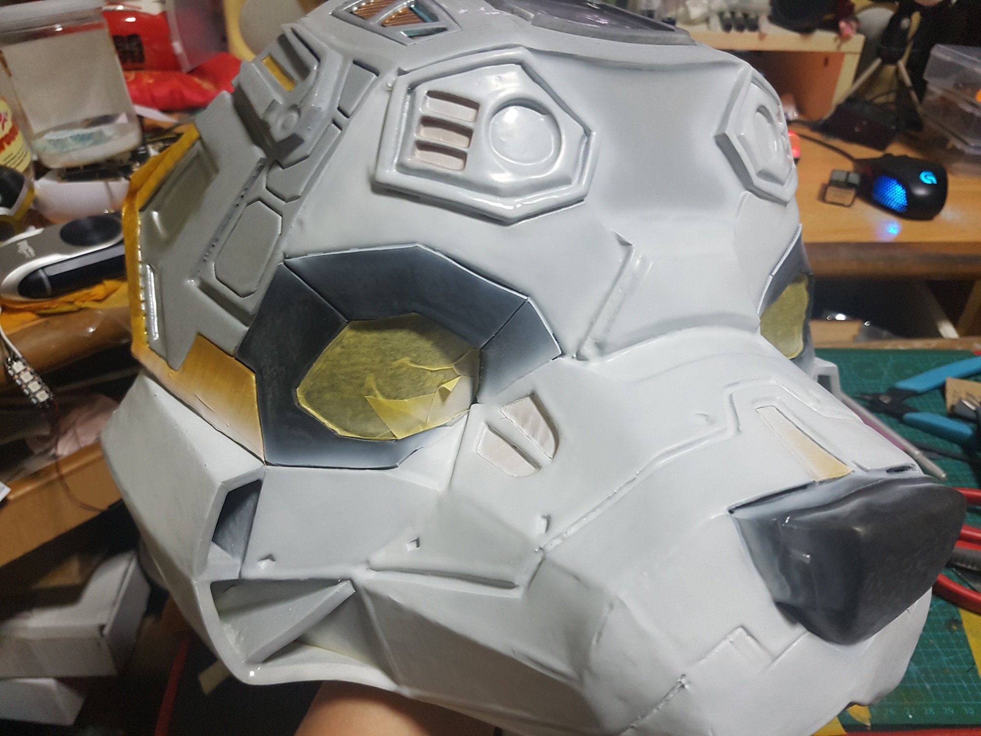
The foam is cut with slanted edge to form an angular joint with the pieces at the side, the curves were made by heating up the EVA foam and bent into place, all connections were made with contact cement to make sure it will last overtime.
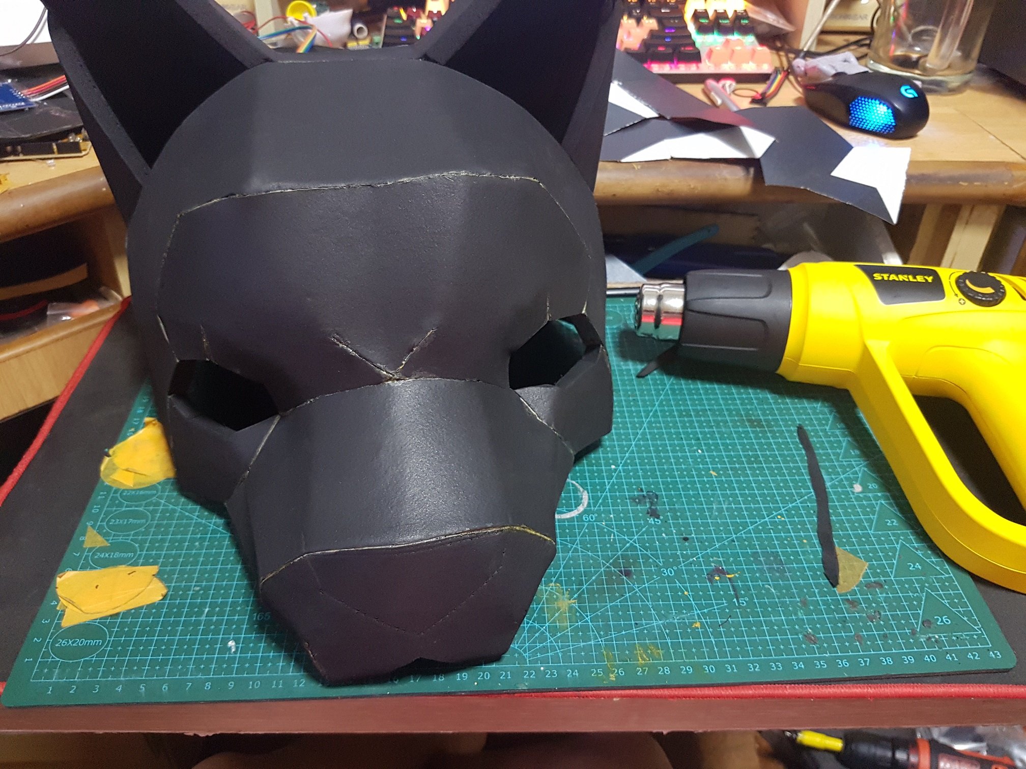
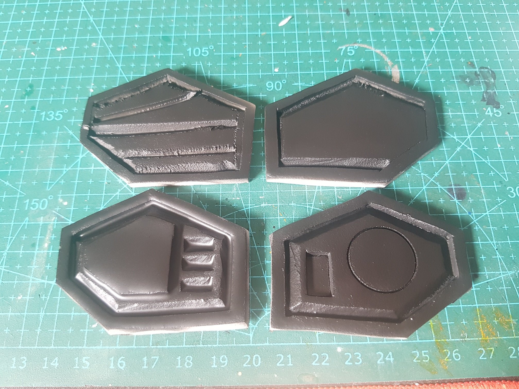
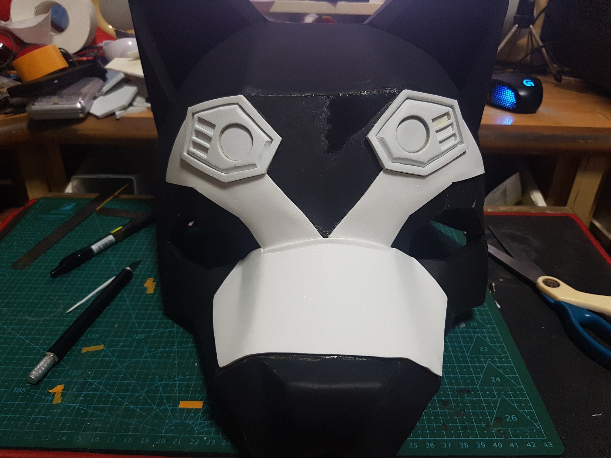
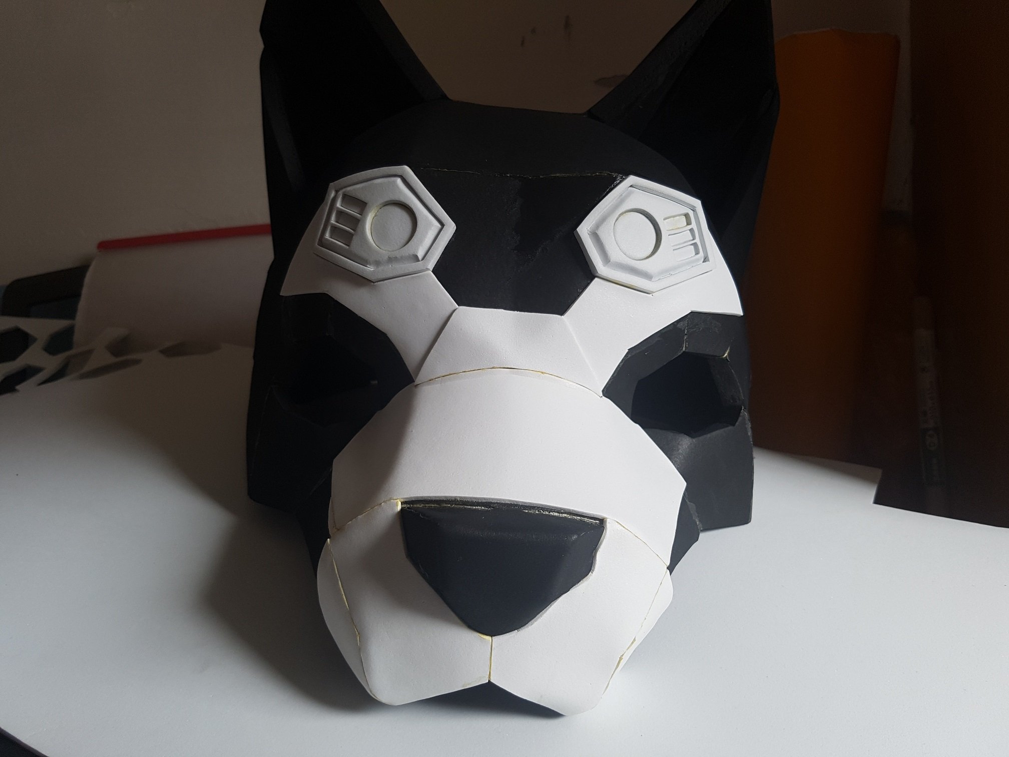
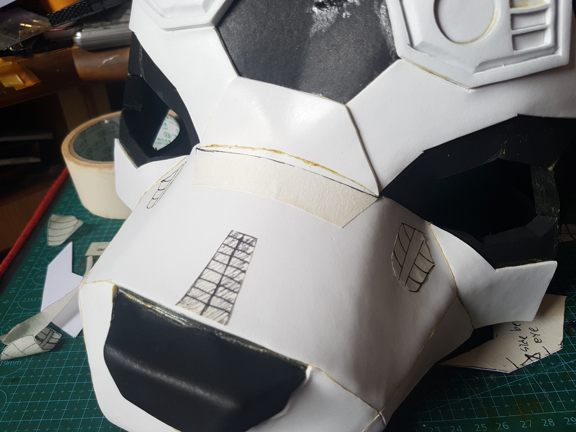
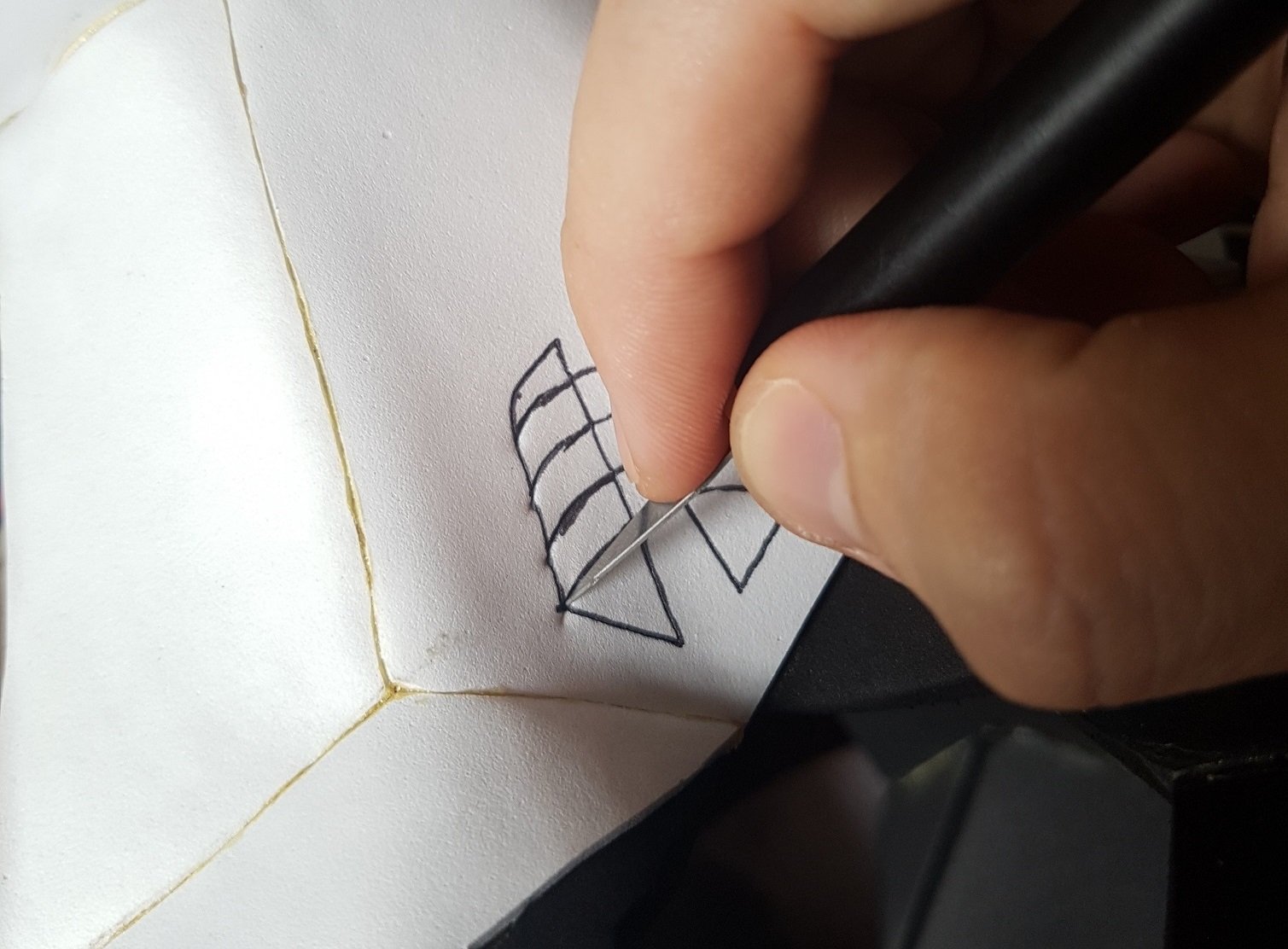
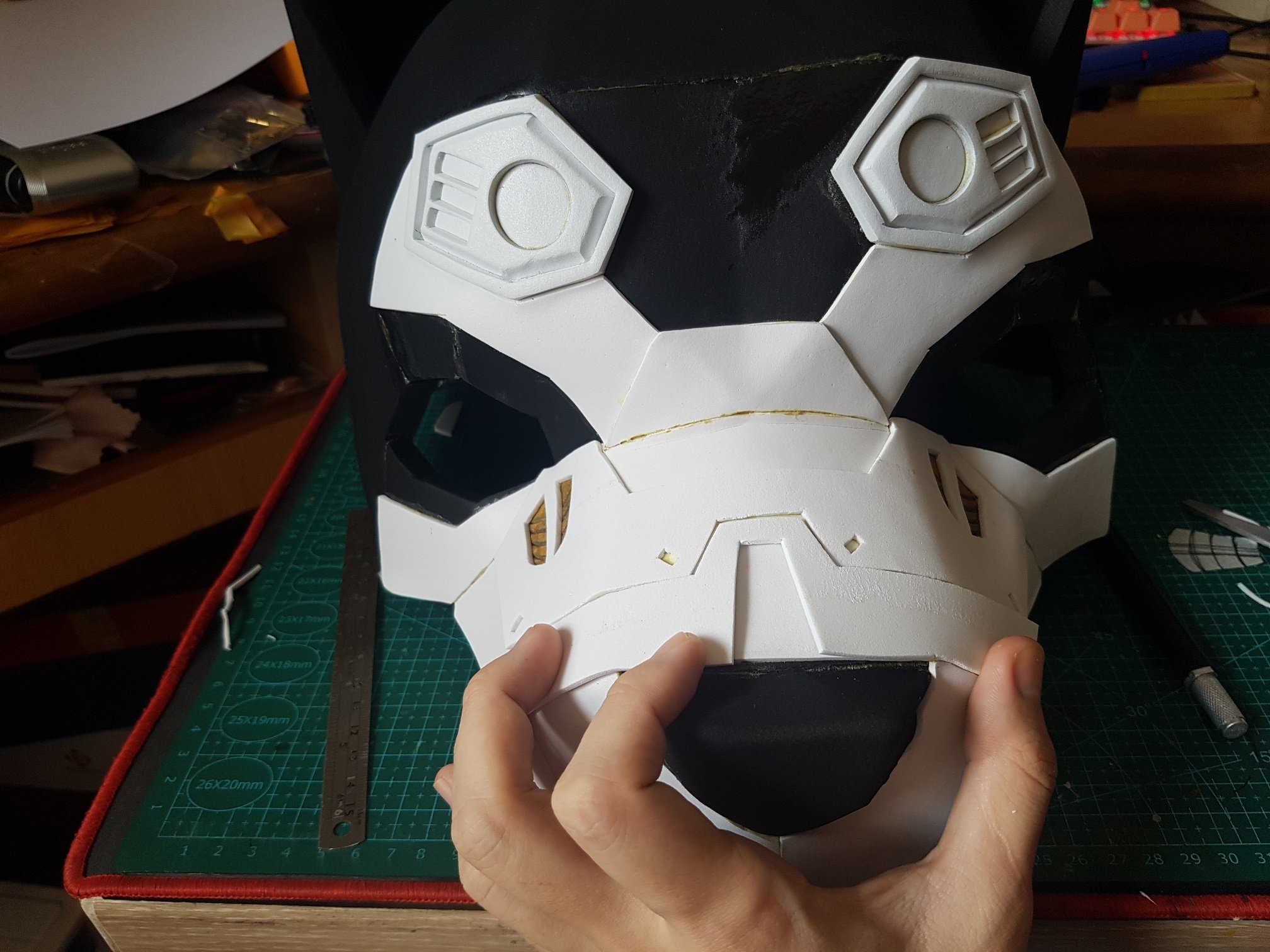
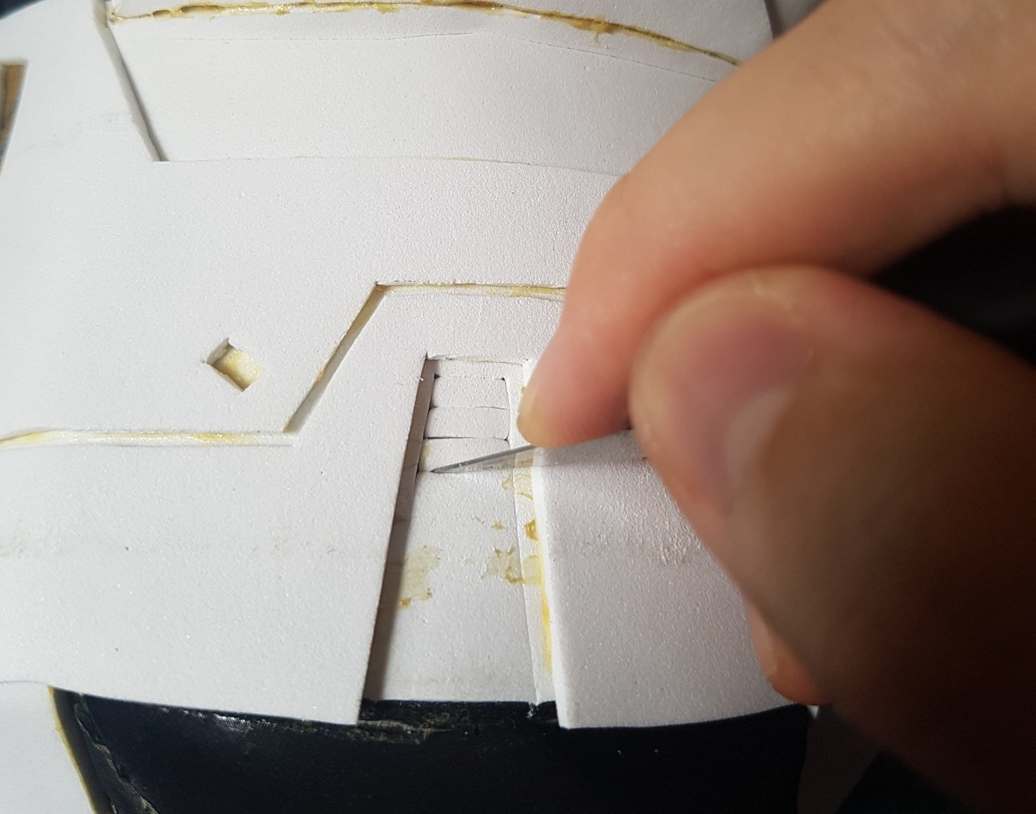
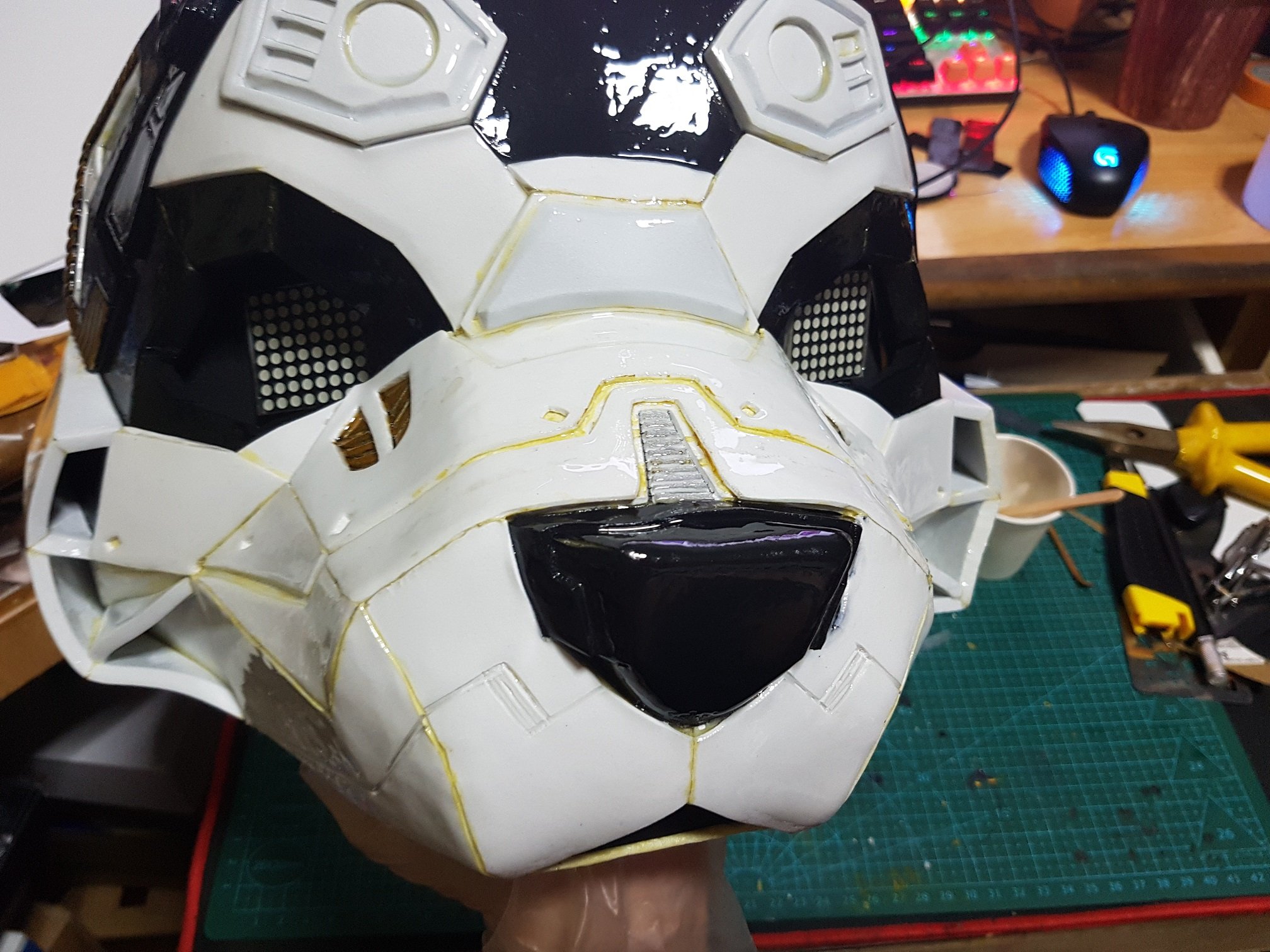
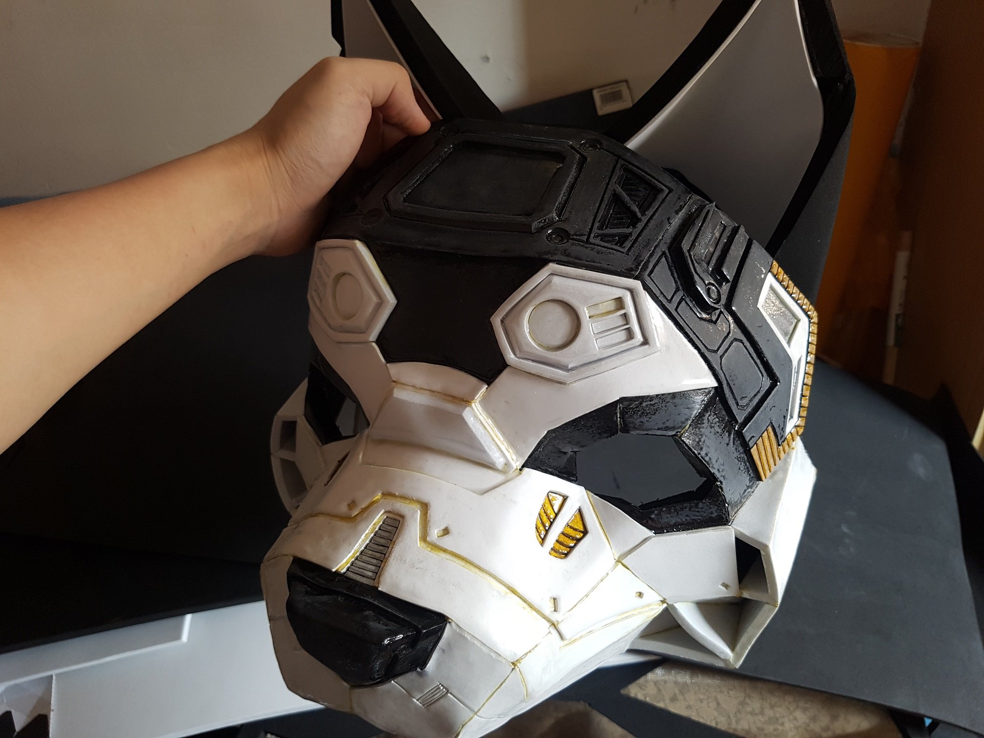
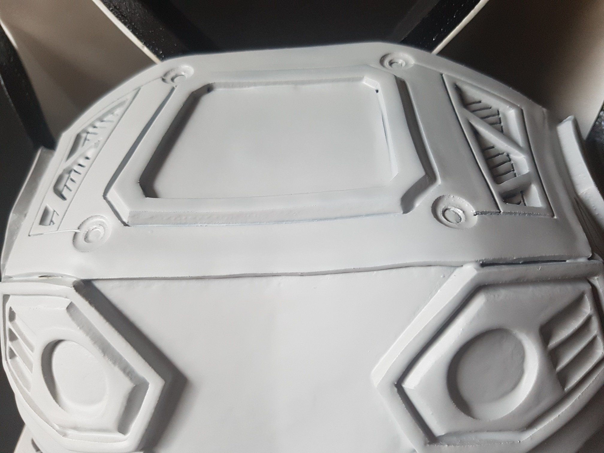
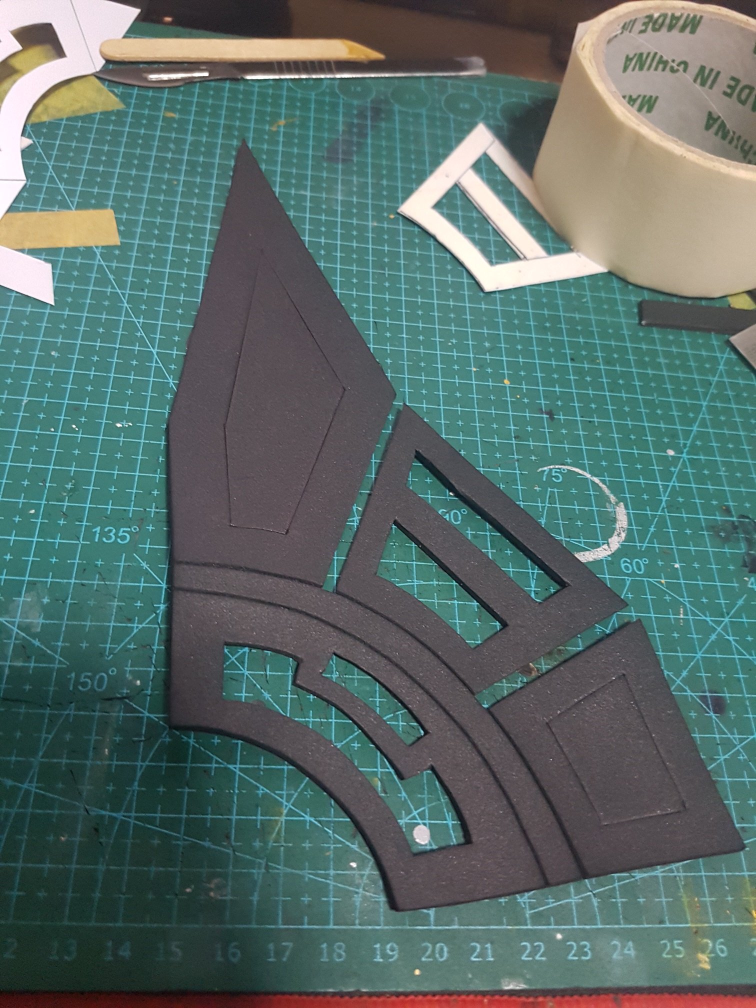
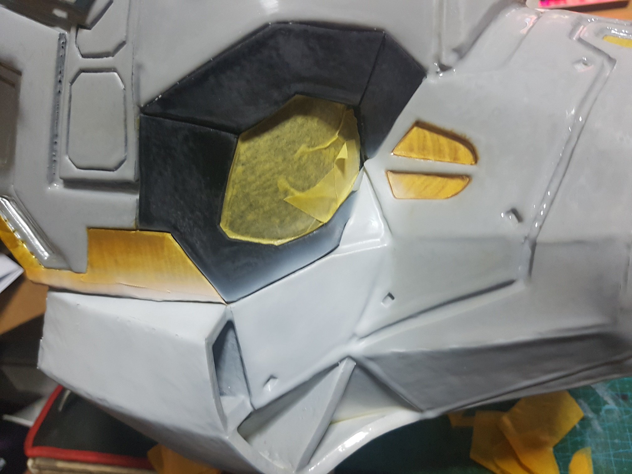
And then, more details were added to the front head.
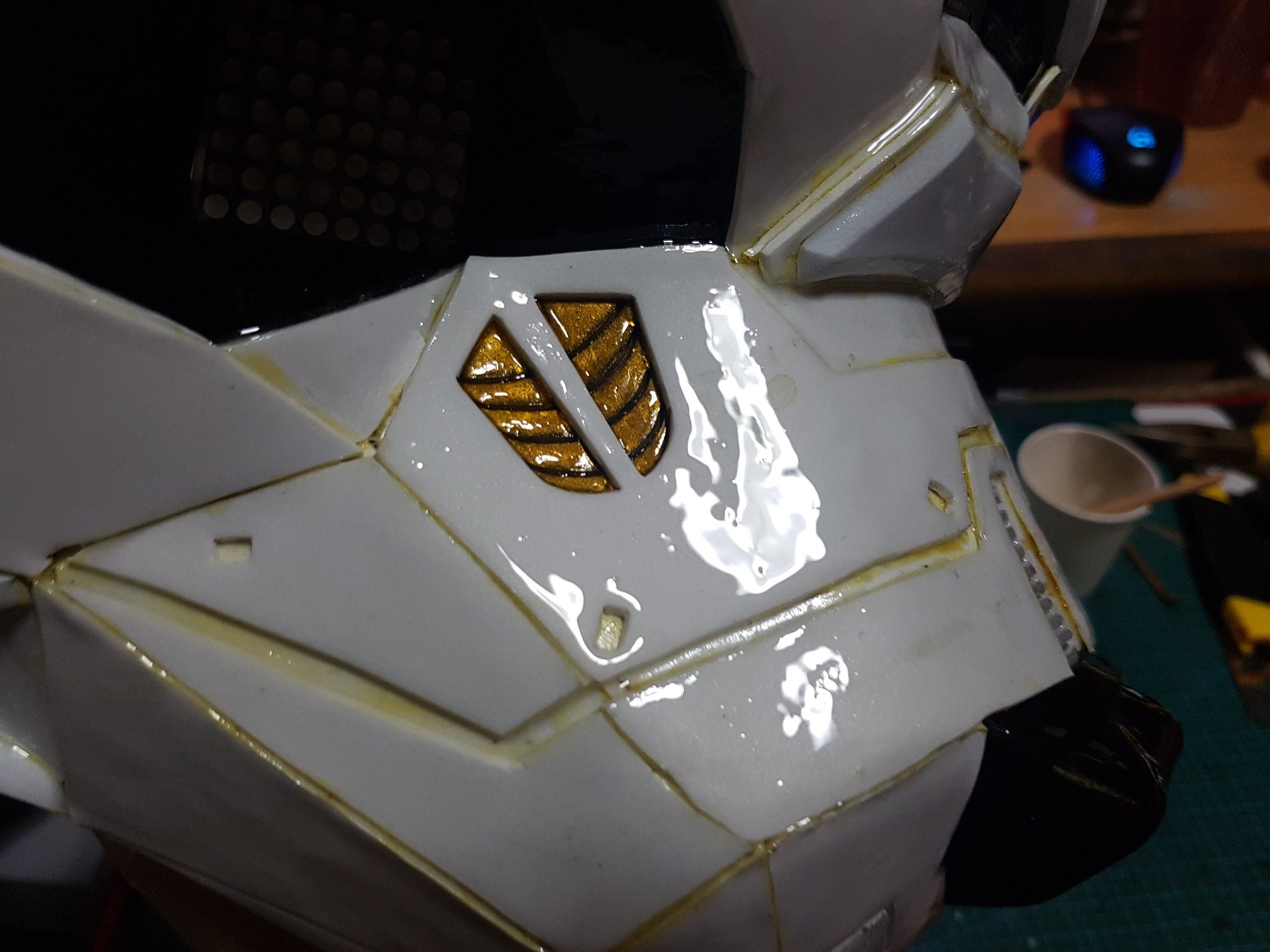
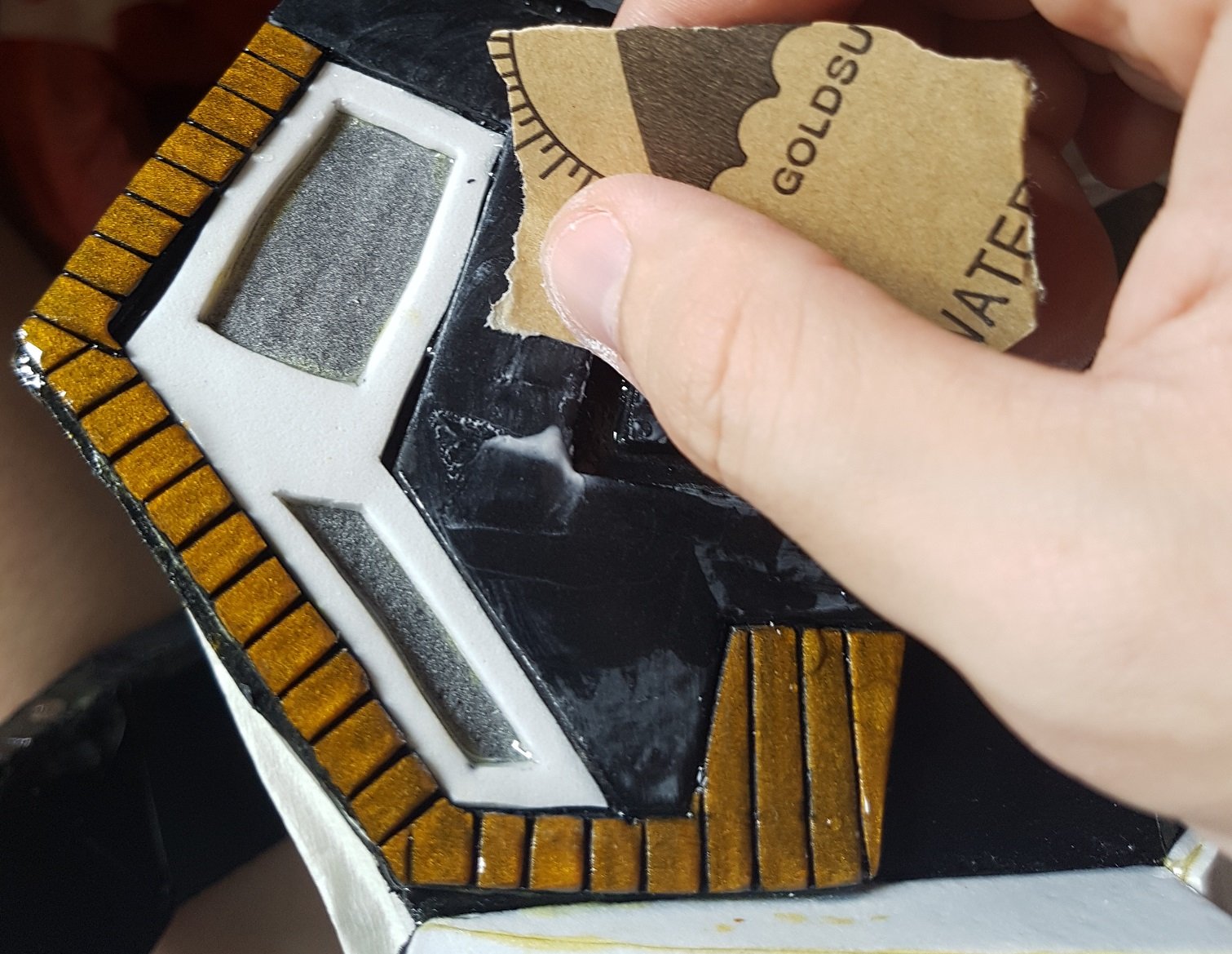
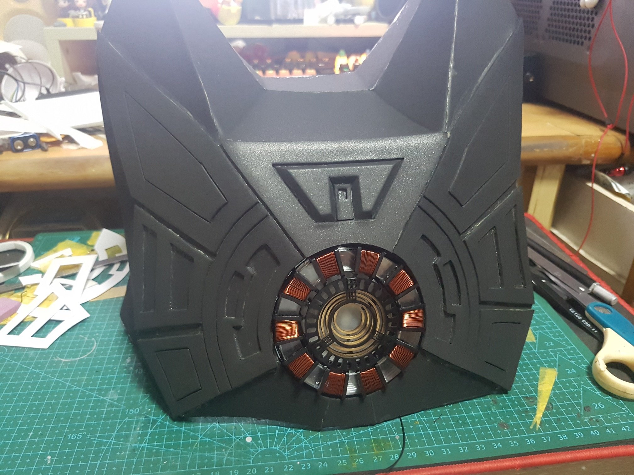
The front were coated with more than 8 coats of resin and sanded which helps the paint to stick onto the head. (this whole process took about 2 weeks as the resin require time to be fully hardened between the layers. plus coating them while prevent dripping and sanding is a labor intensive process)
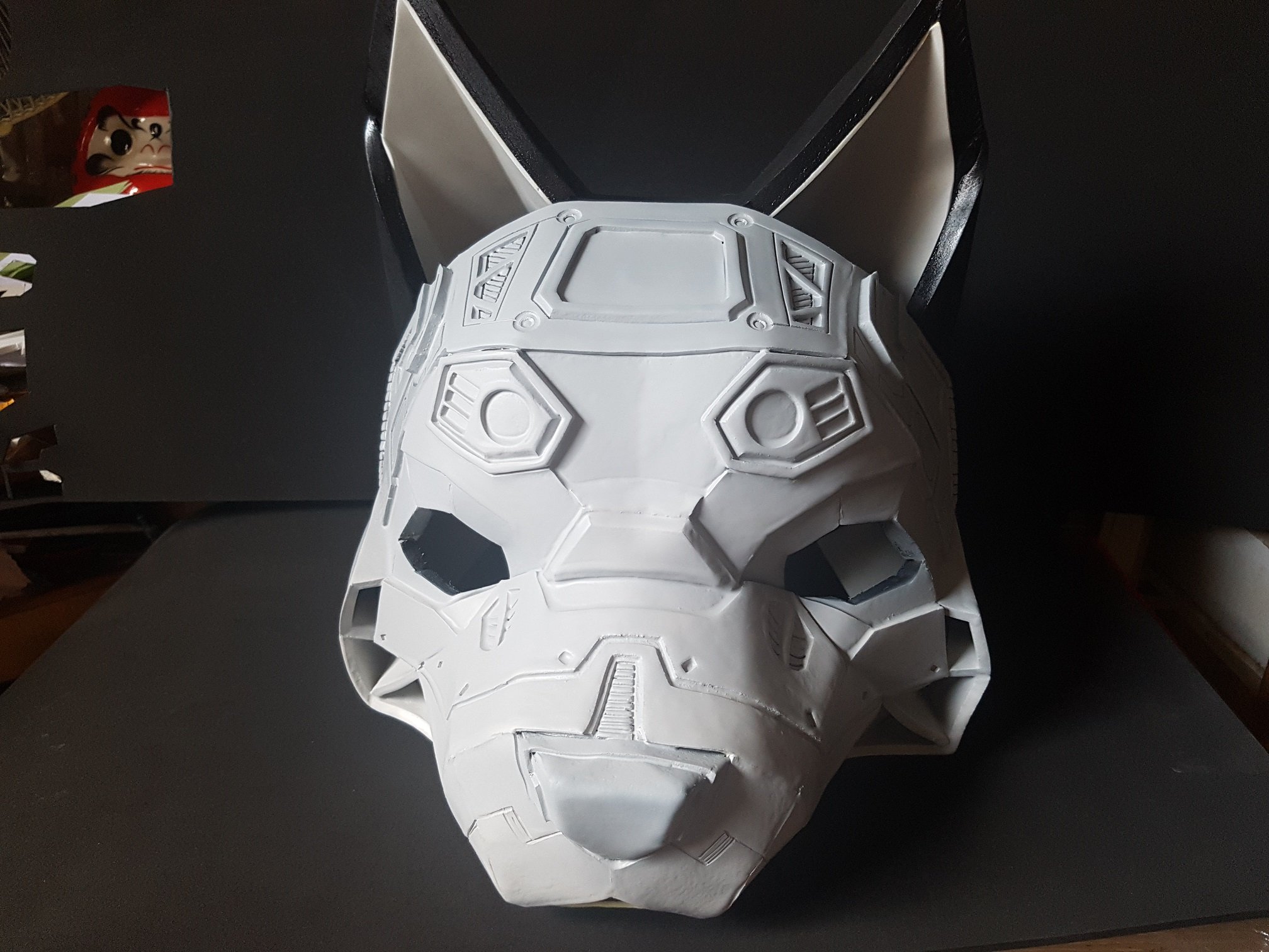
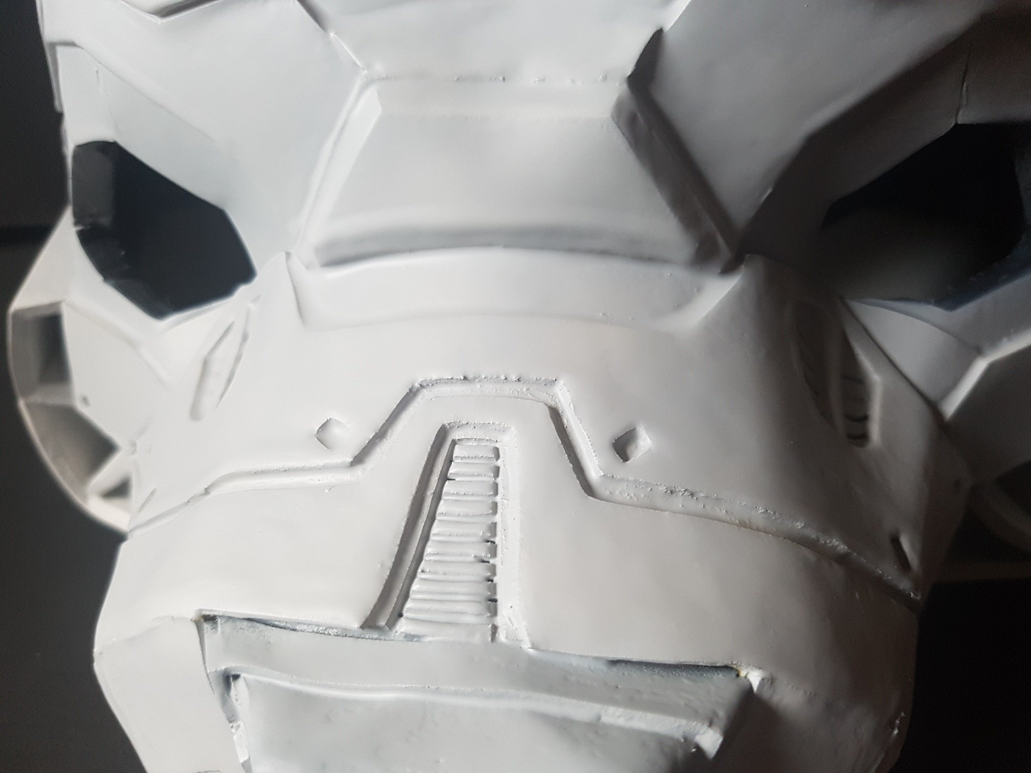
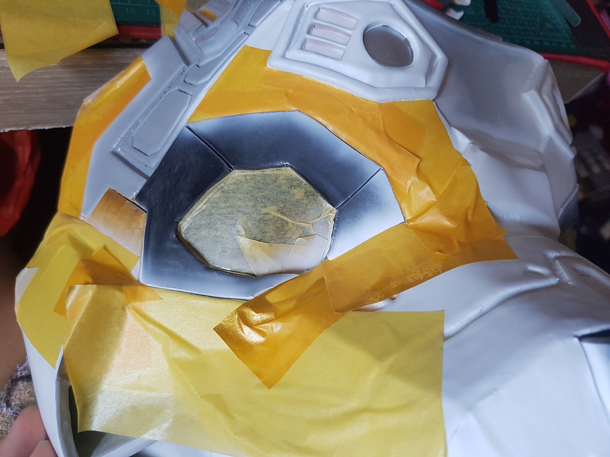
and then, the sanded head were airbrushed with primer (to help the paint stick to the head, and also help me to see the surface quality like checking of small bumbs)
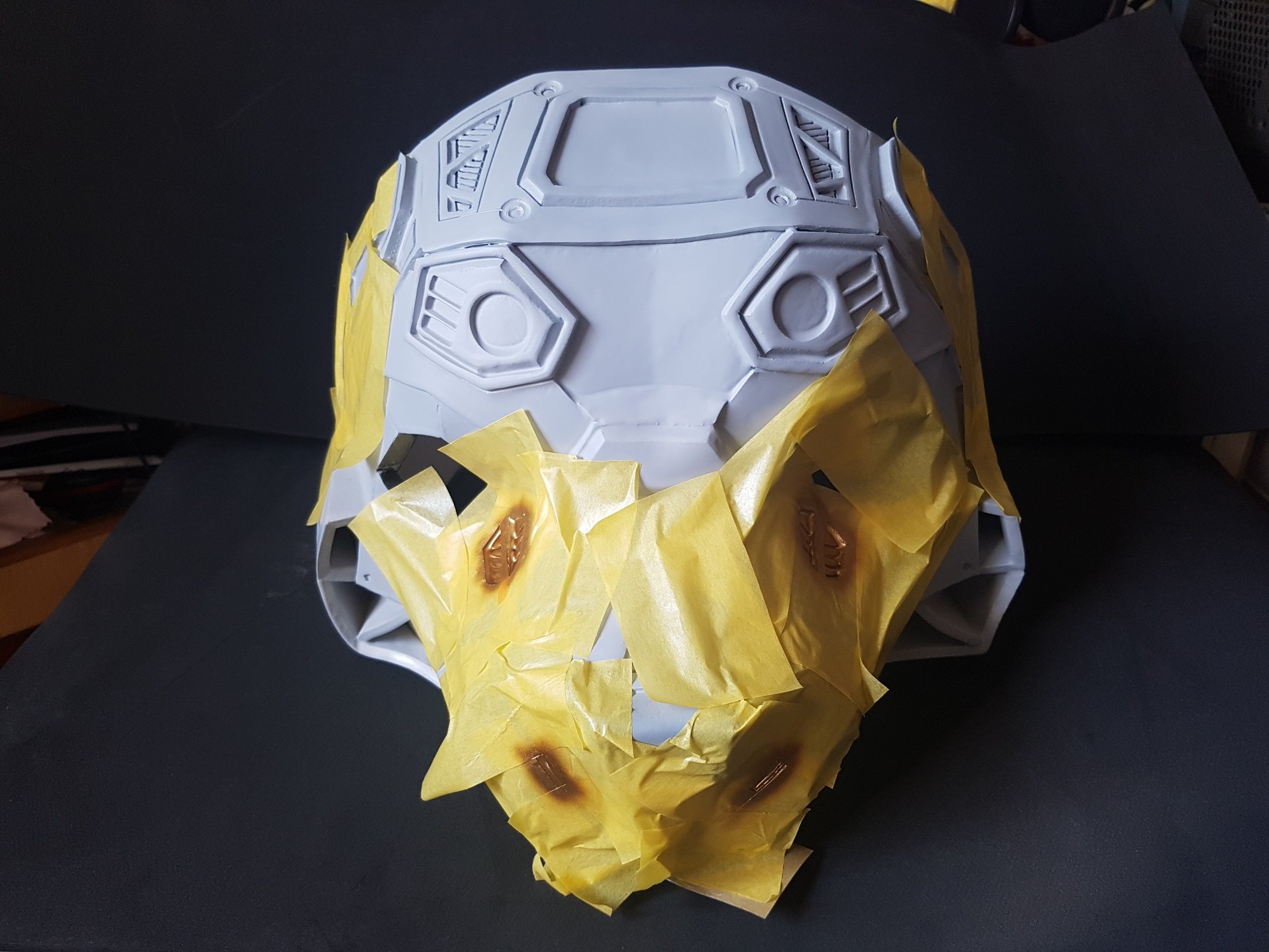
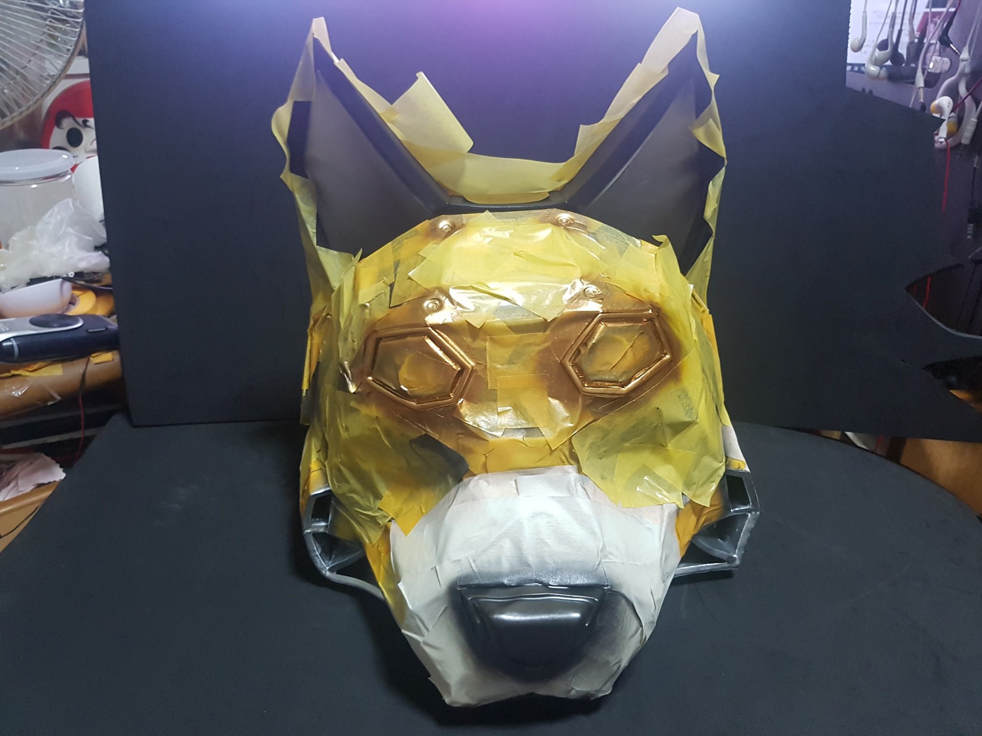
After a few primer coat and sanding between the coats, the head were sprayed and mask to create a clean and beautiful spray job.
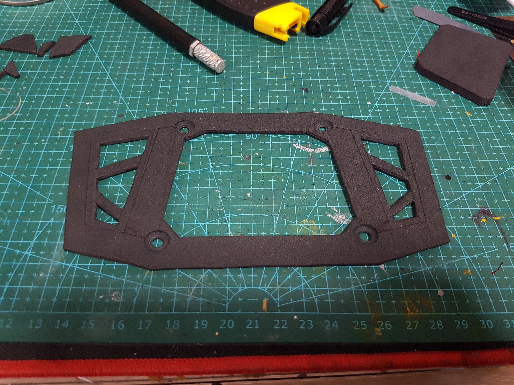
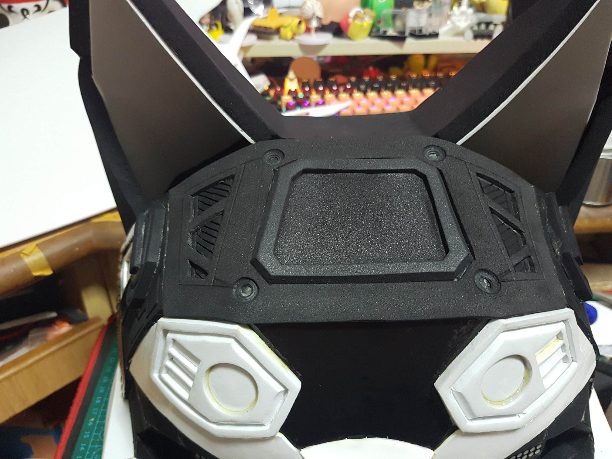
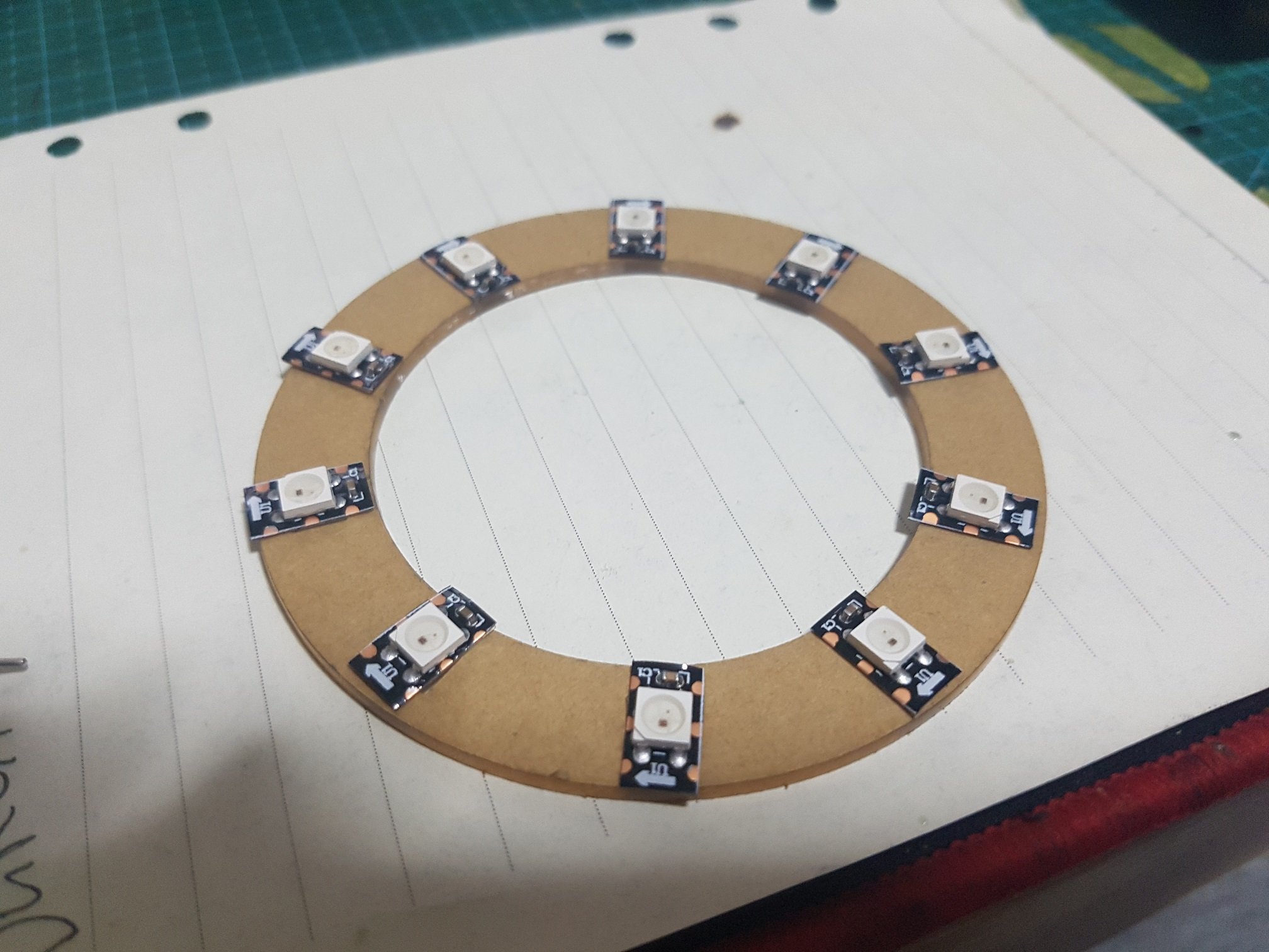
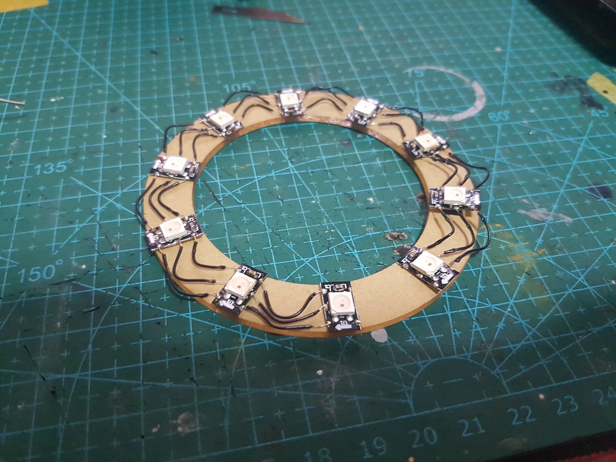
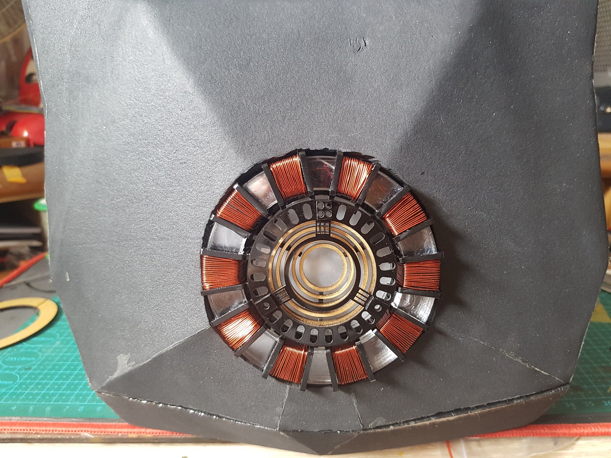
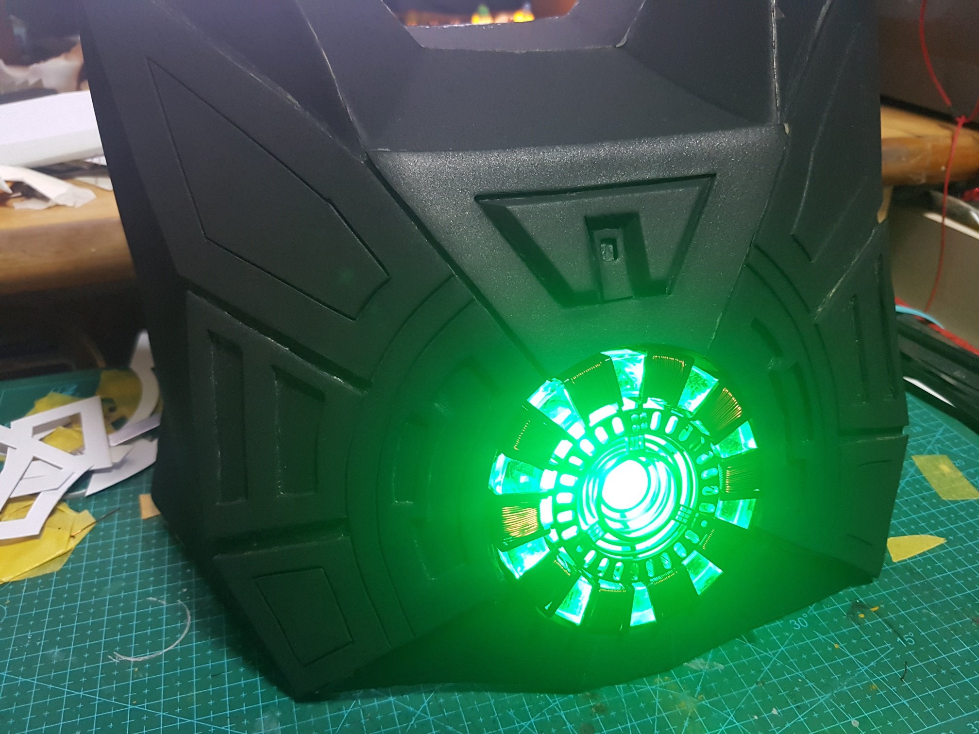
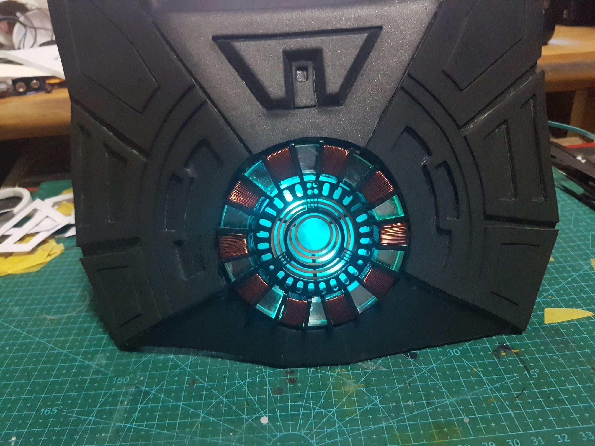
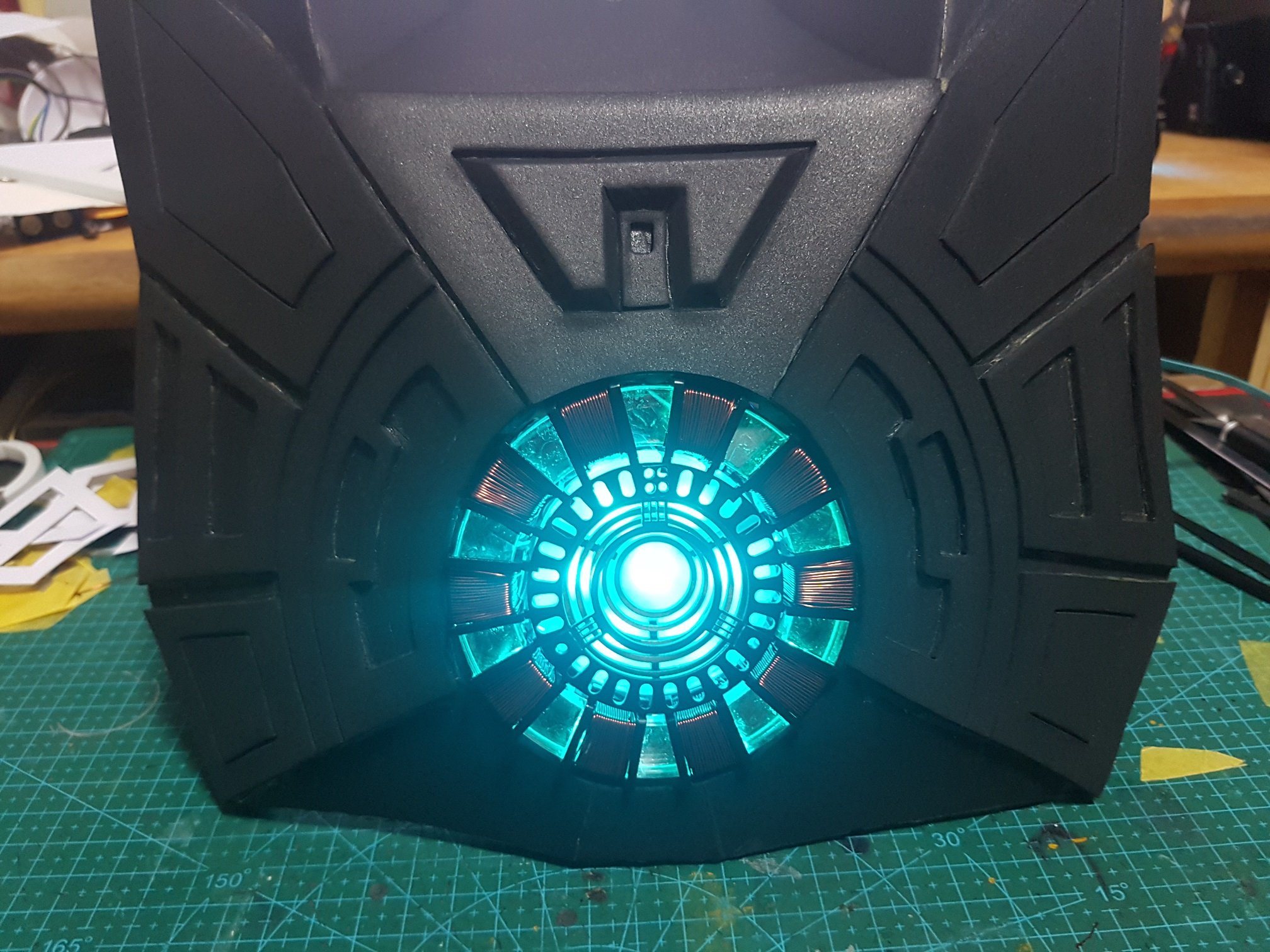
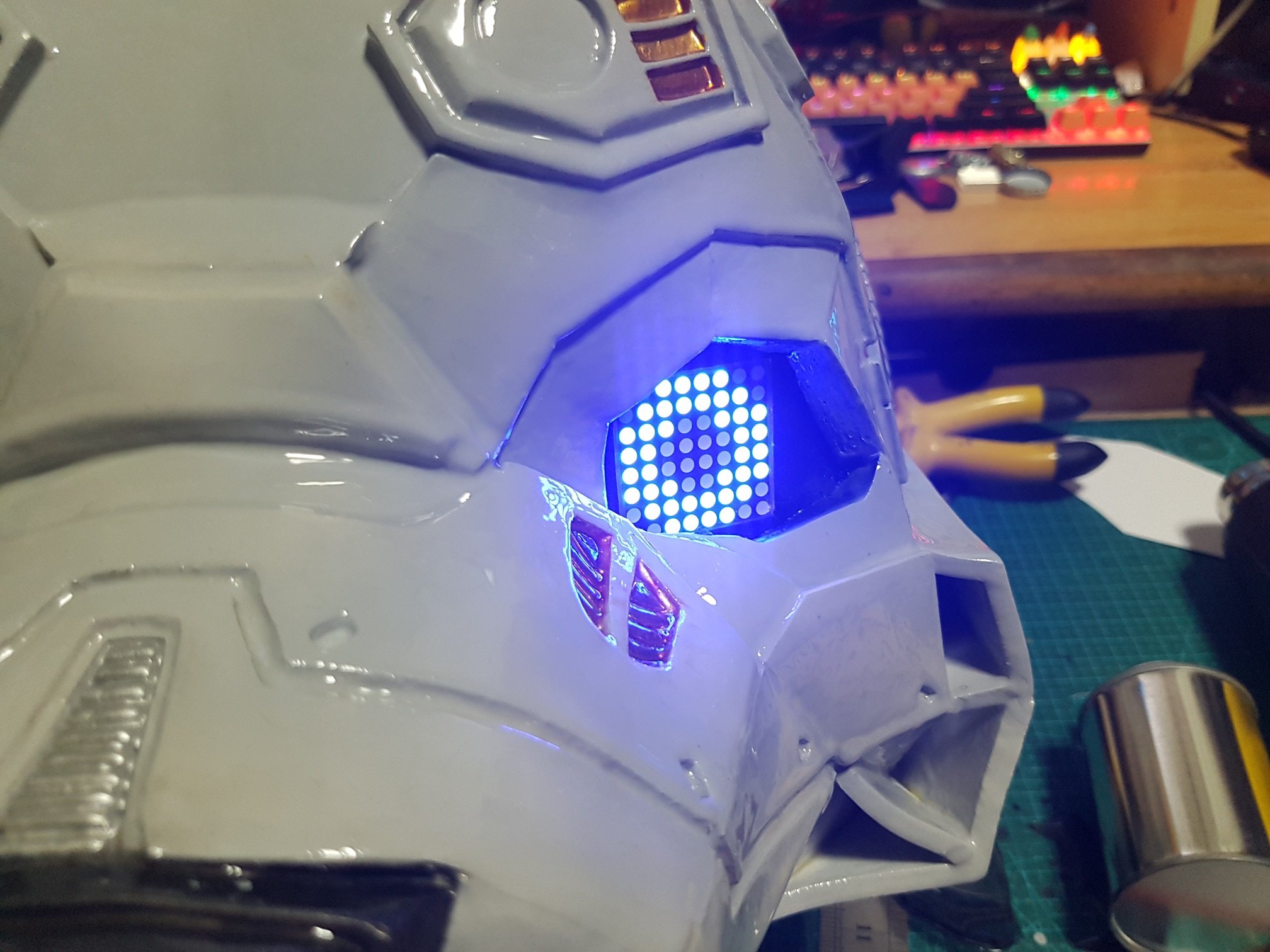
for the back of the head, details were built with laser-cut parts while LED were soldered and installed.
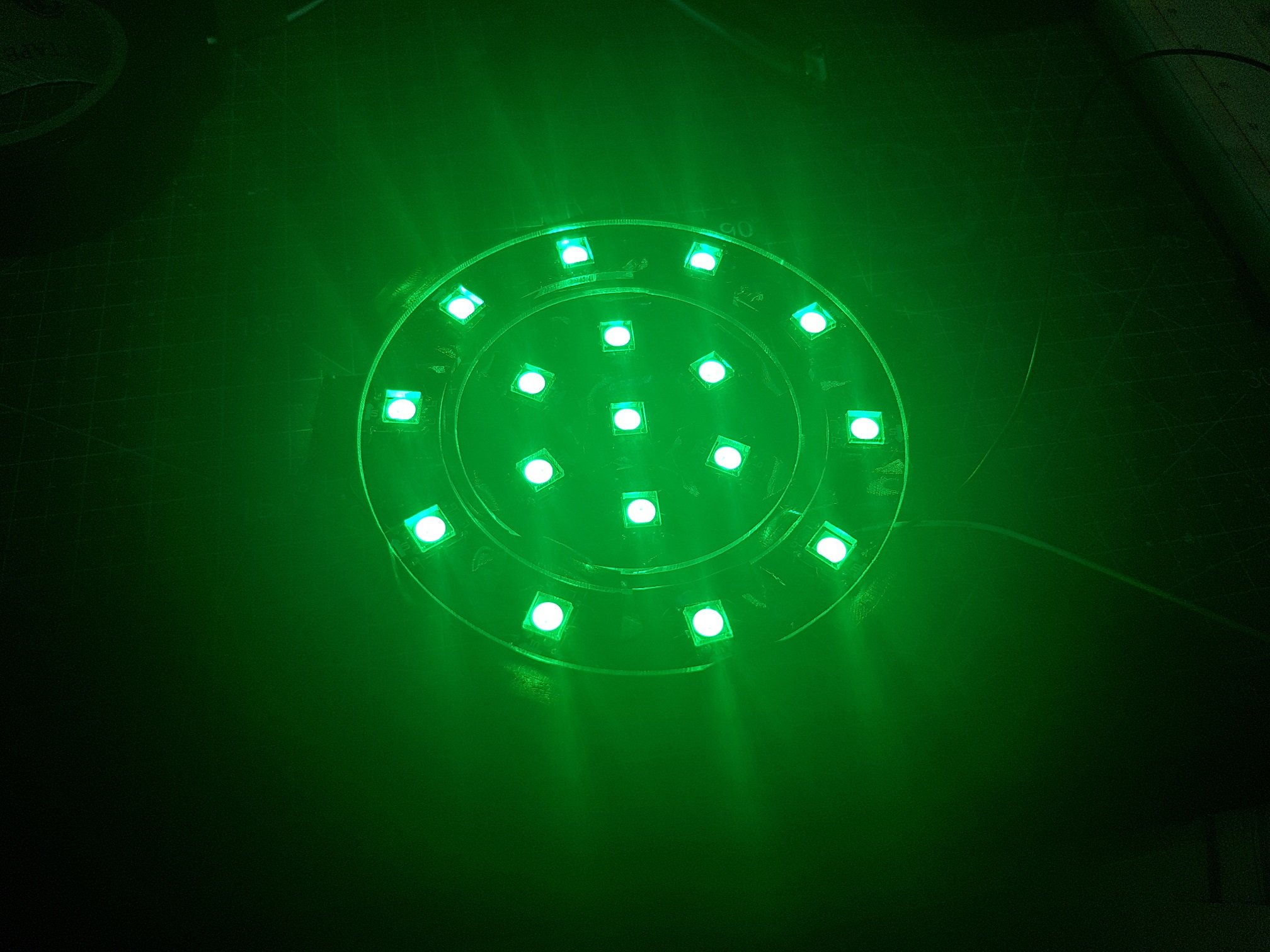
then, like the front, details were drawn and cut out from EVA foam and sticked onto the back of the head with contact cement. the LED on the back were also tested to see which colour combination looks the best.
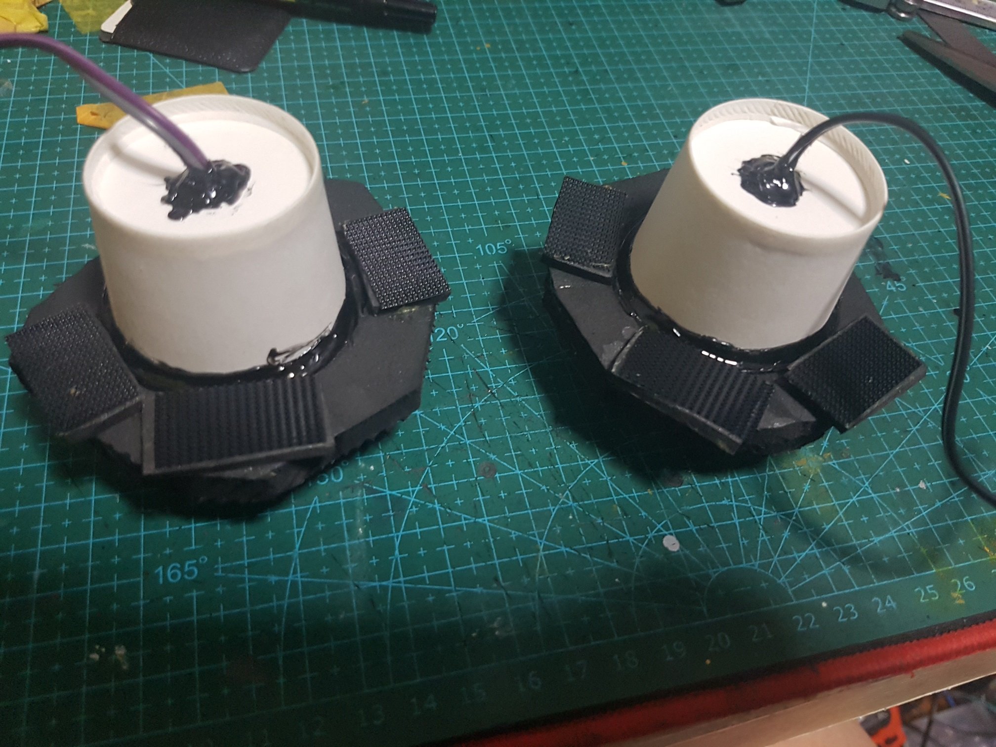
As same with the front, the back were resin-coated with many layers and then sanded and primed, meanwhile, for the internal structure, speakers were soldered and installed inside the ear with properly placed velcro to help with maintenance in the future.
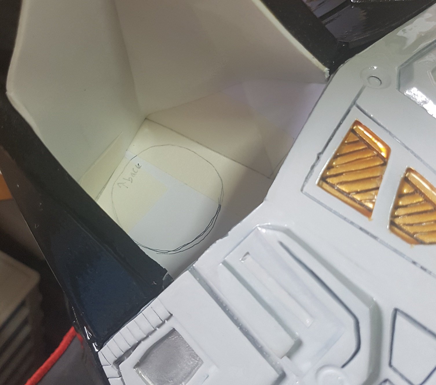
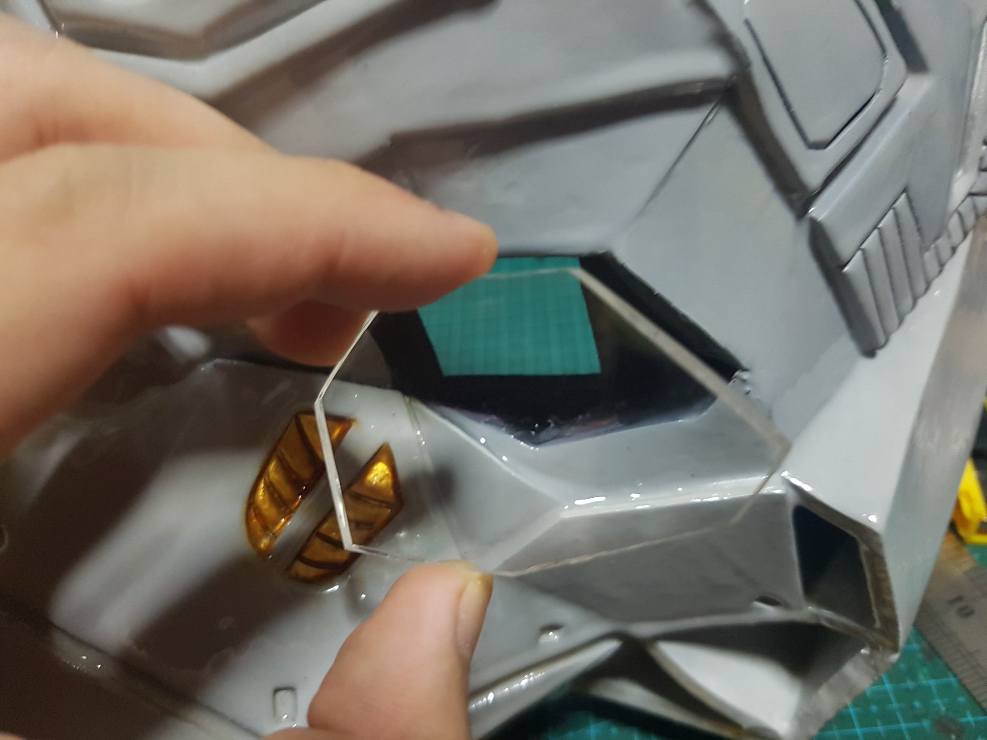
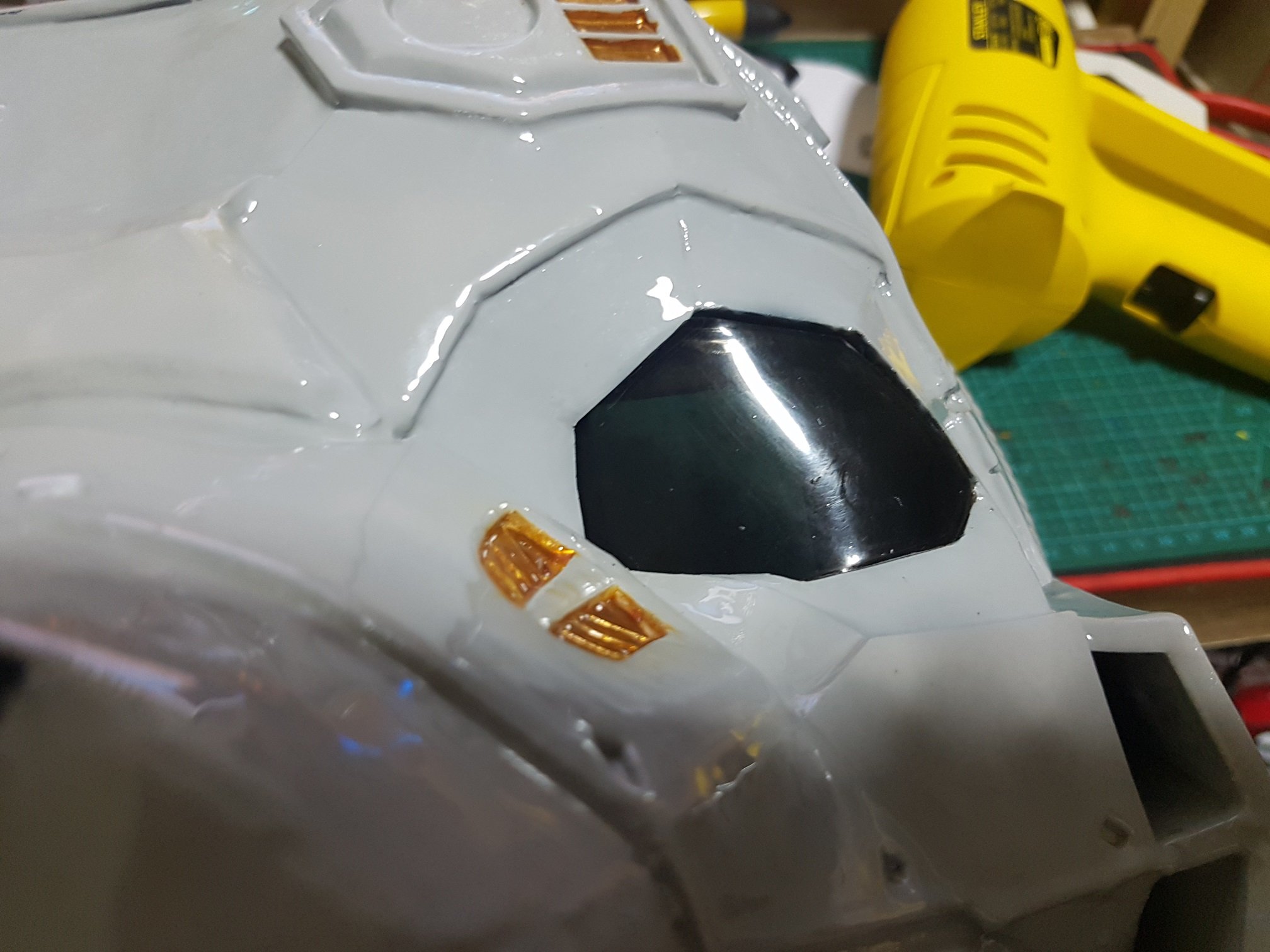
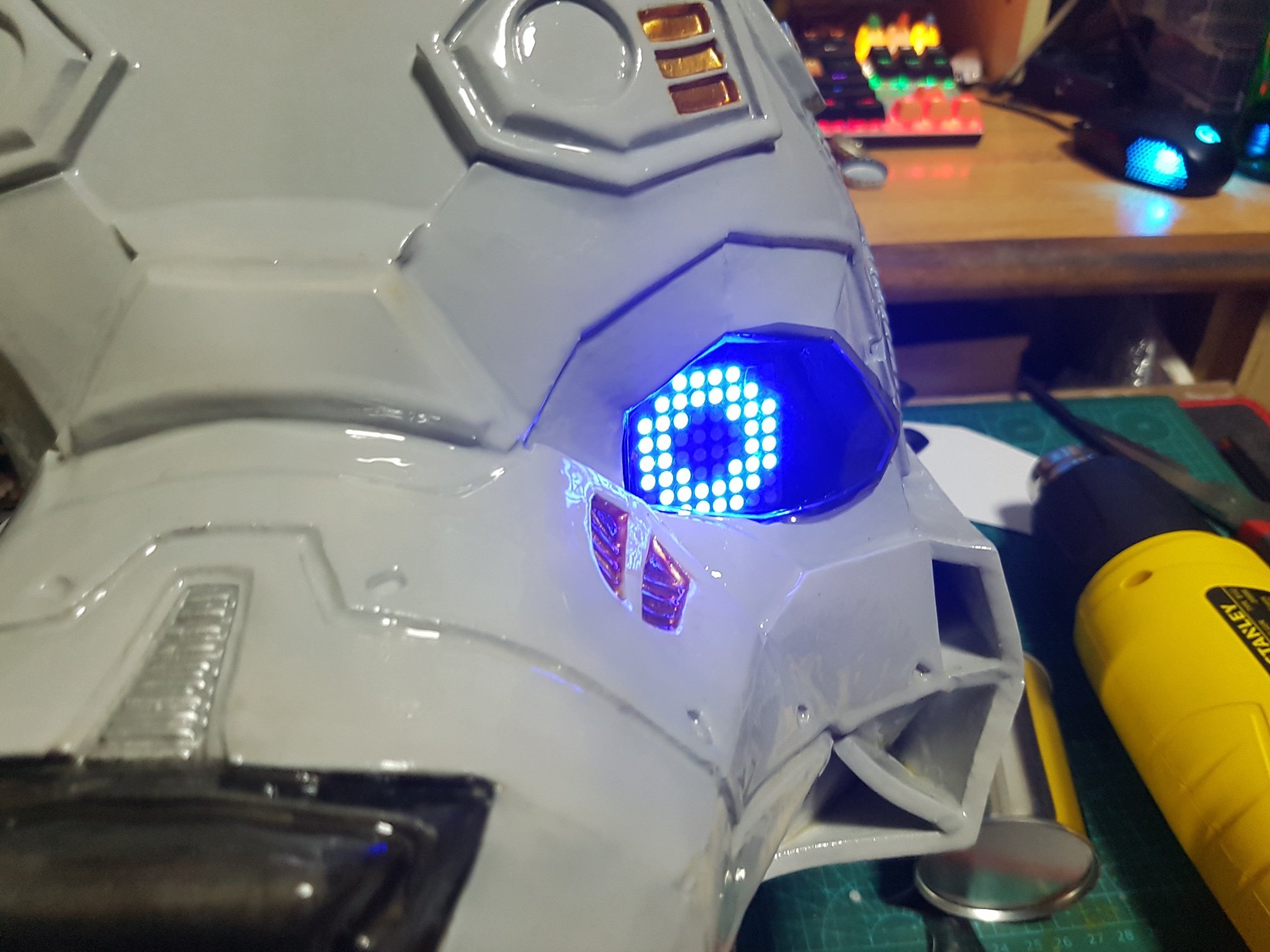
for the front of head, acrylic pieces were cut and melted with hot air gun to provide a protective cover for the eye, which two layer of tinted coat were sticked on it to darken the overall feeling and gives it a more compelling eye to the dog head.(and it affect greatly on the quality of the eye on camera, which I hope people will be taking photo/video of it during the FYP show.)
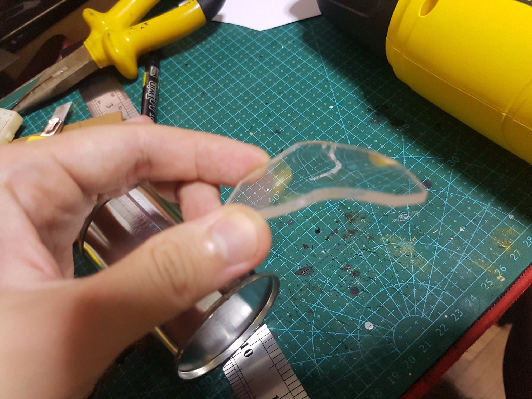
acrylic piece cut
heat air gun and bent,
acrylic bent
no tint layer,
1 tint layer
2 tint layers
no acrylic
1 tint layer acrylic
2 tint layer acrylic
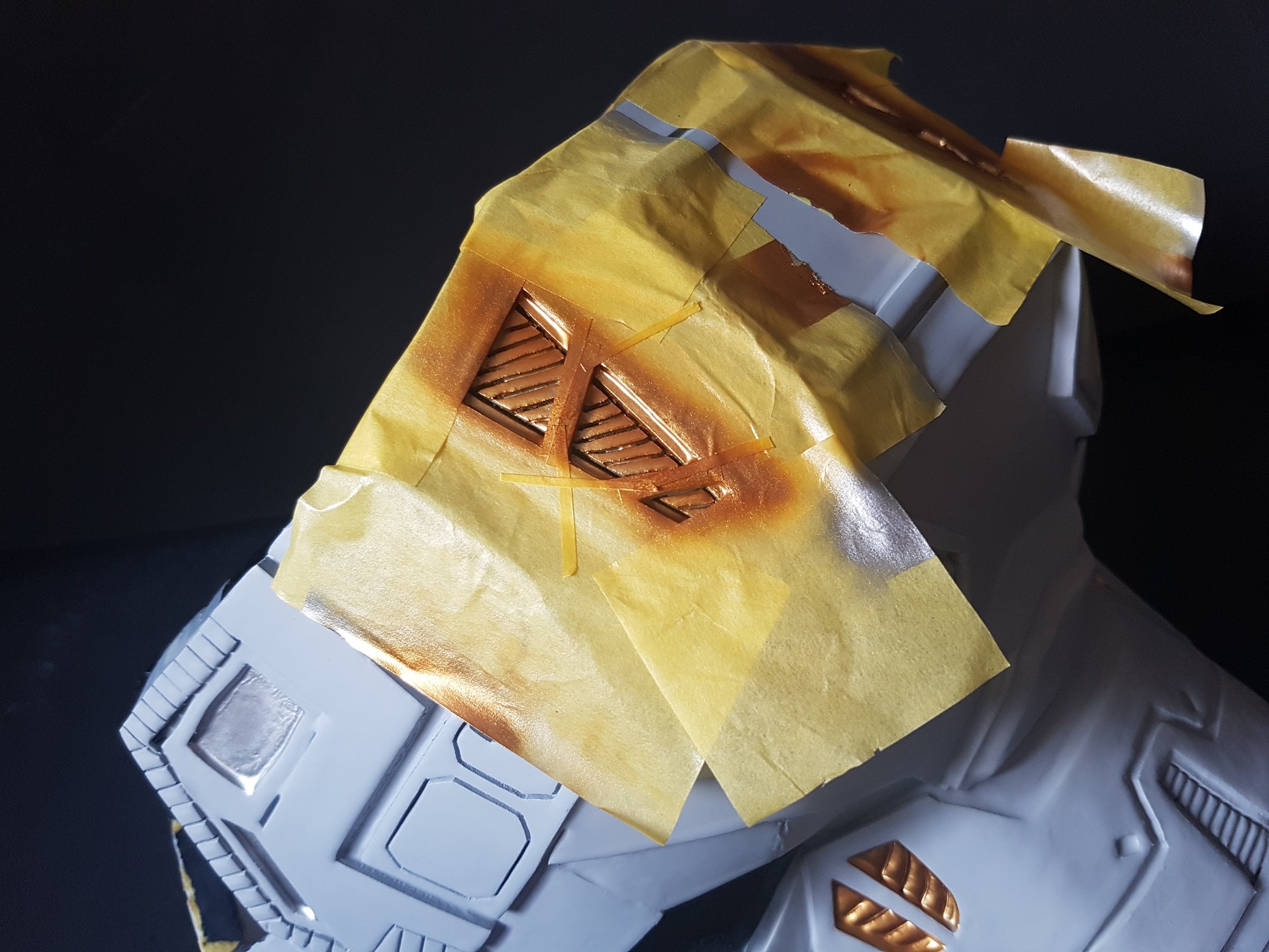
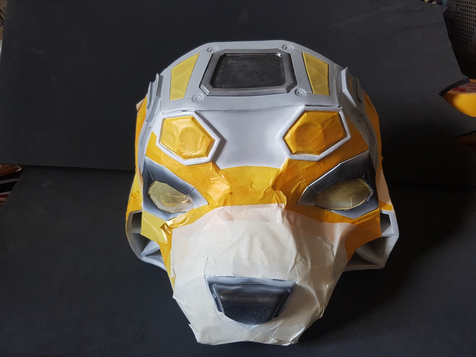
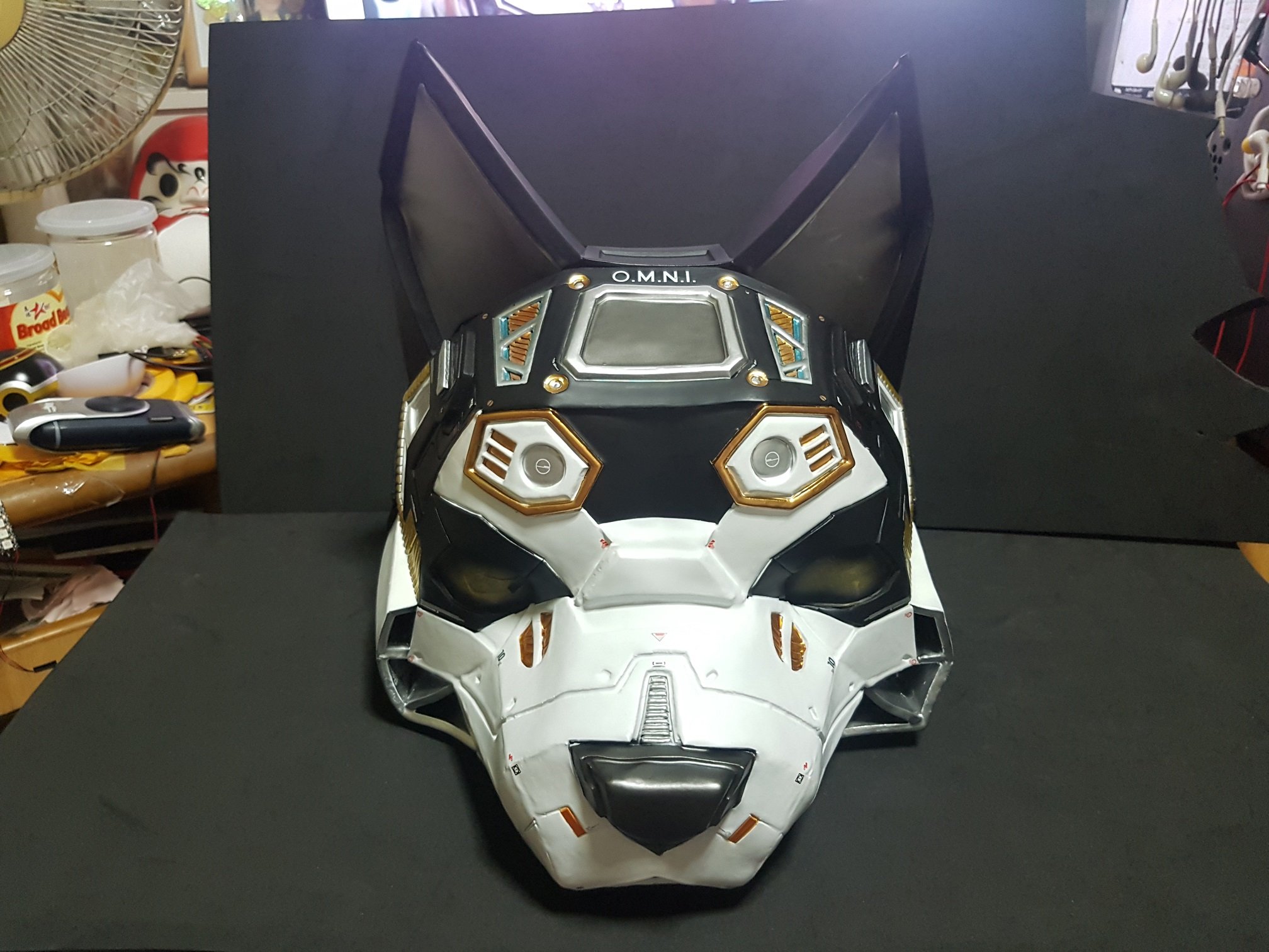
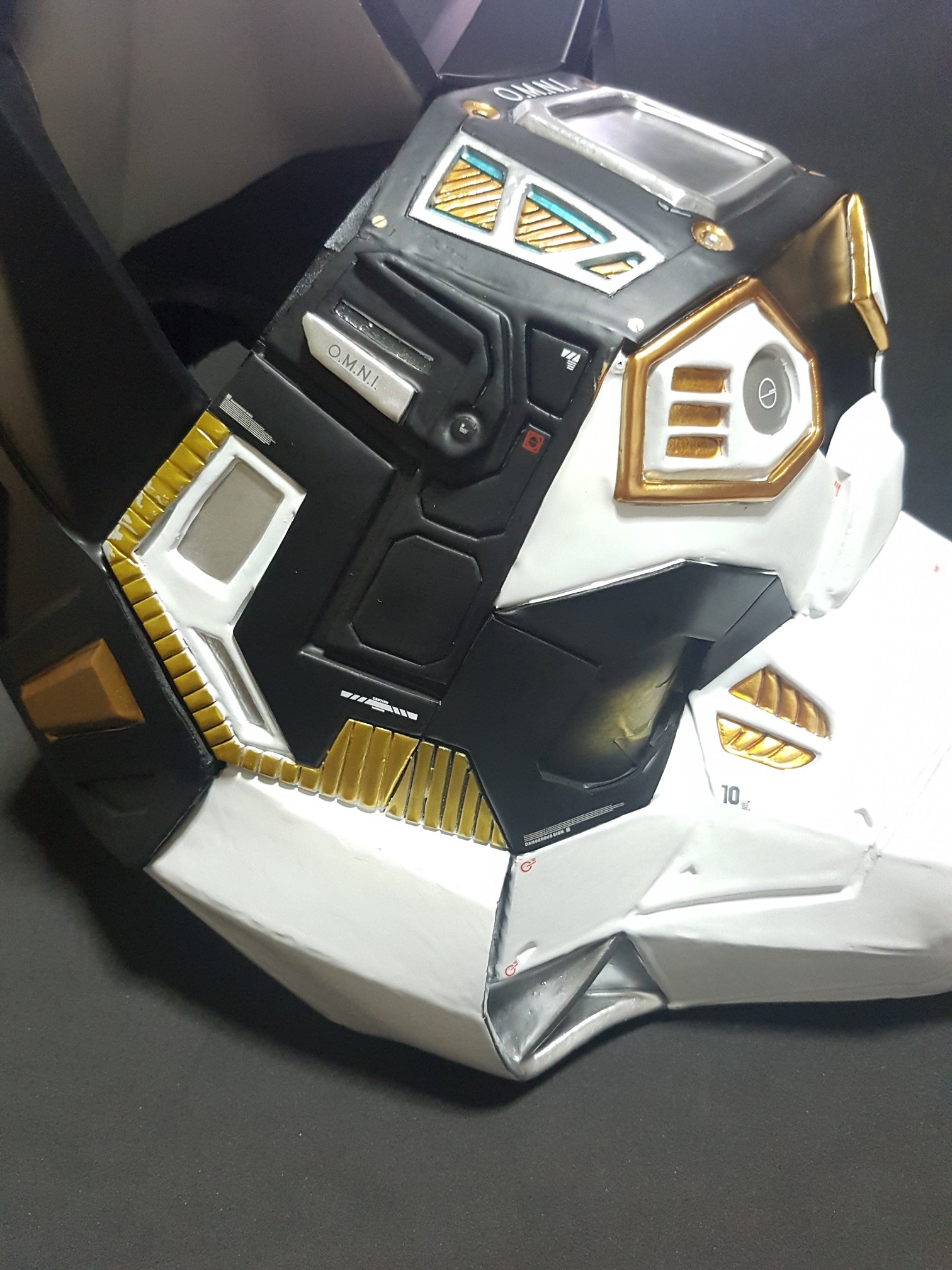
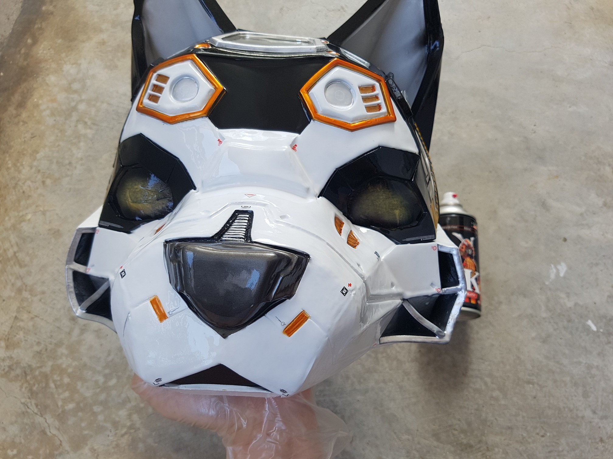
afterwhich, the dog head were masked and sprayed in many layers with model paint.
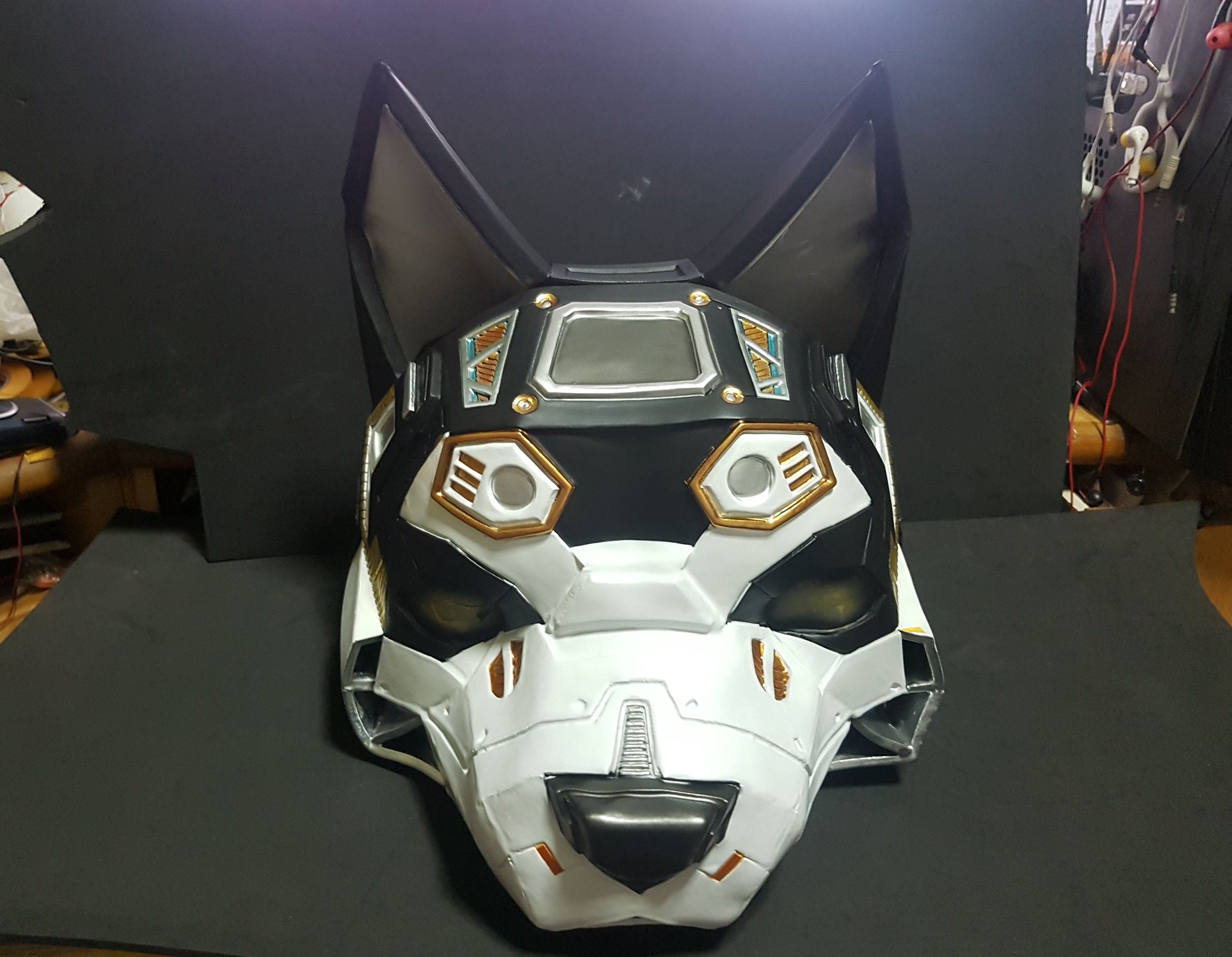
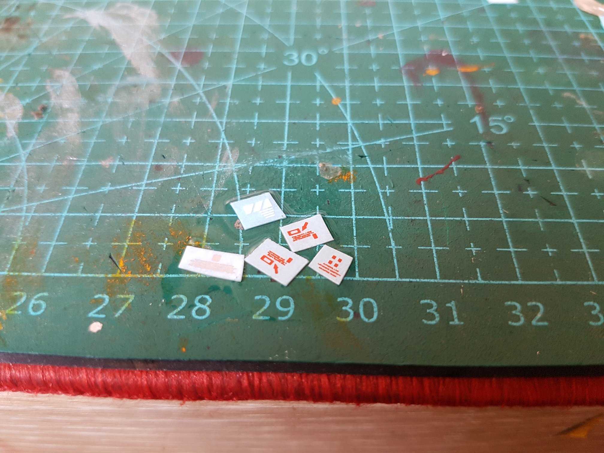
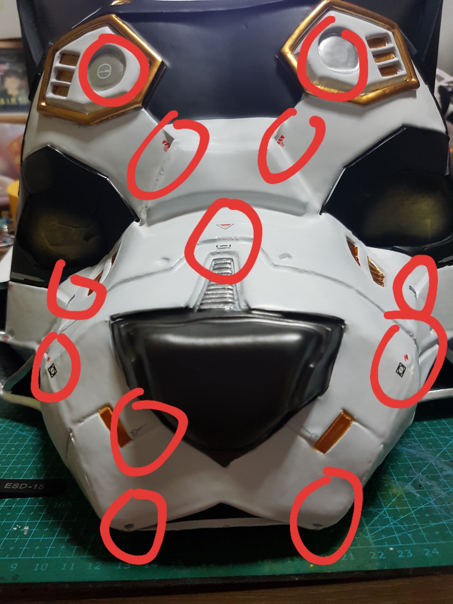
towards the final after the base colours were masked and sprayed, the corners were touched up with small brush. Water decals from toy models were added to the head to give it a more interesting finishing and make the finishing completed. As in my research, I found that small details is the key factor that differentiate a normal artwork and a insanely impressive one.
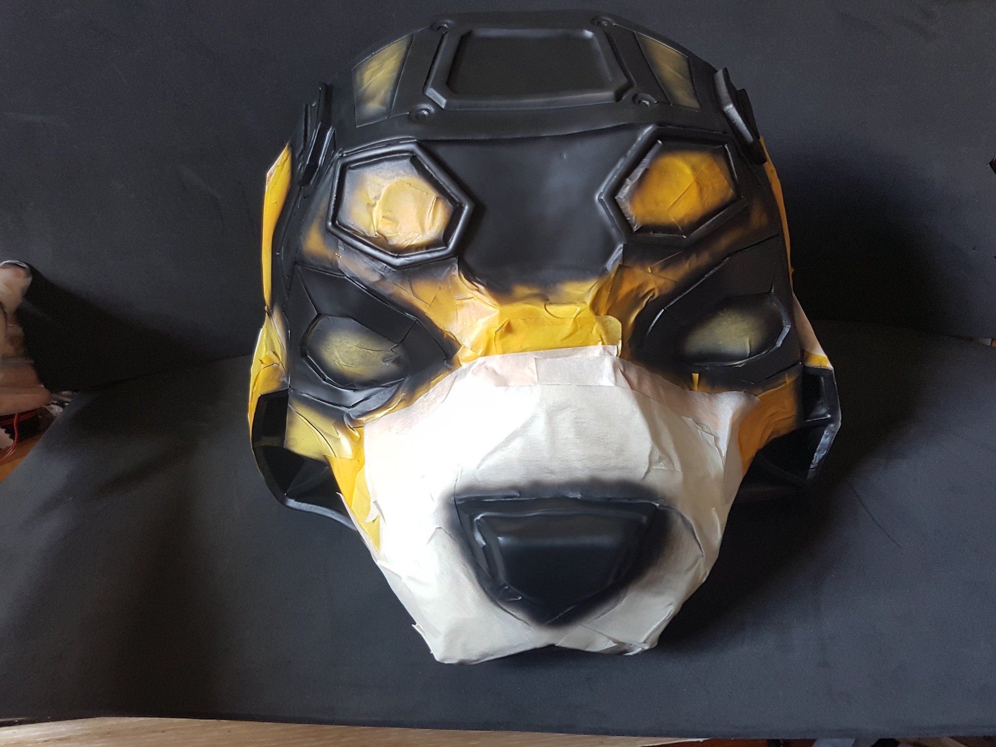
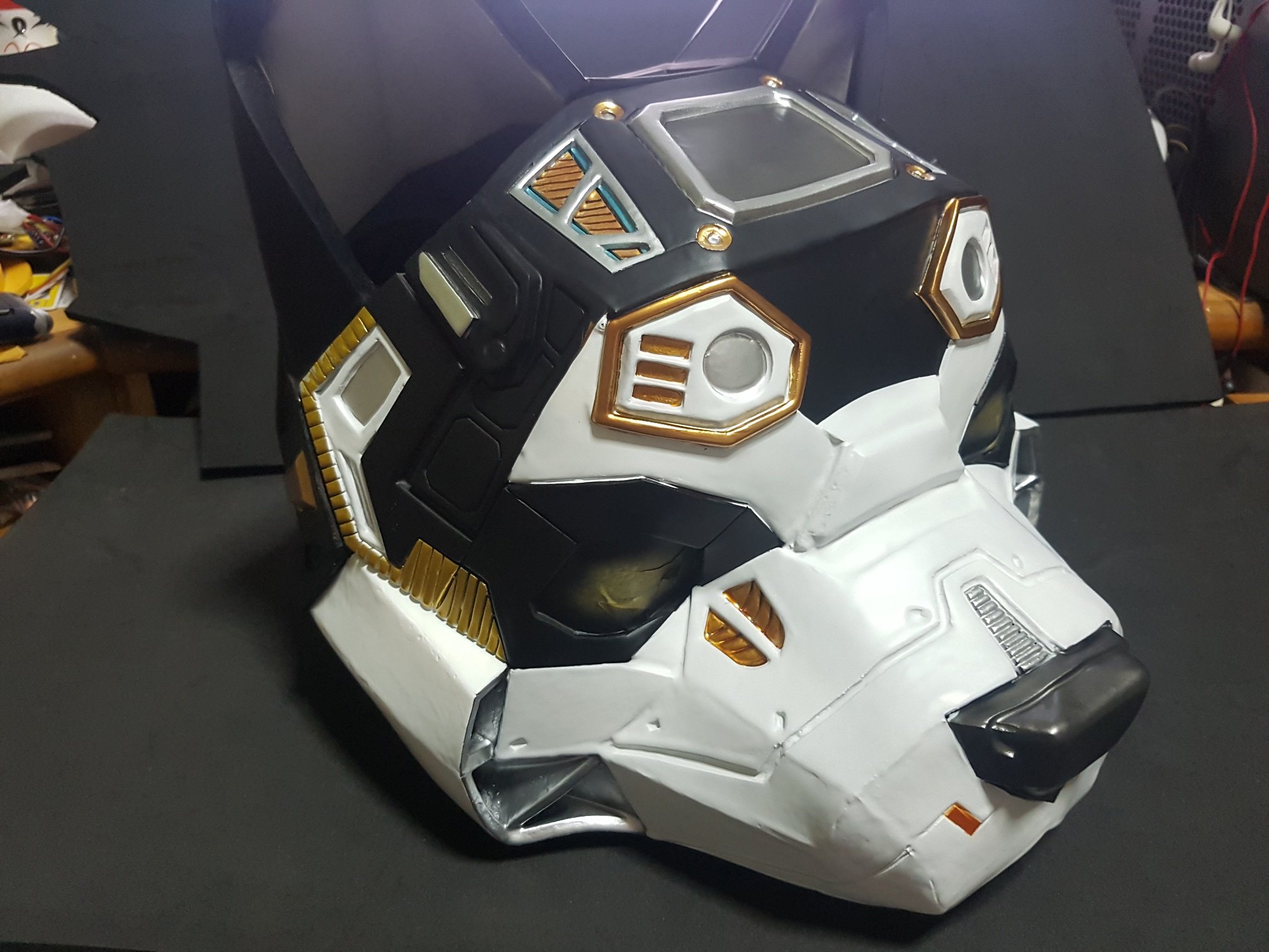
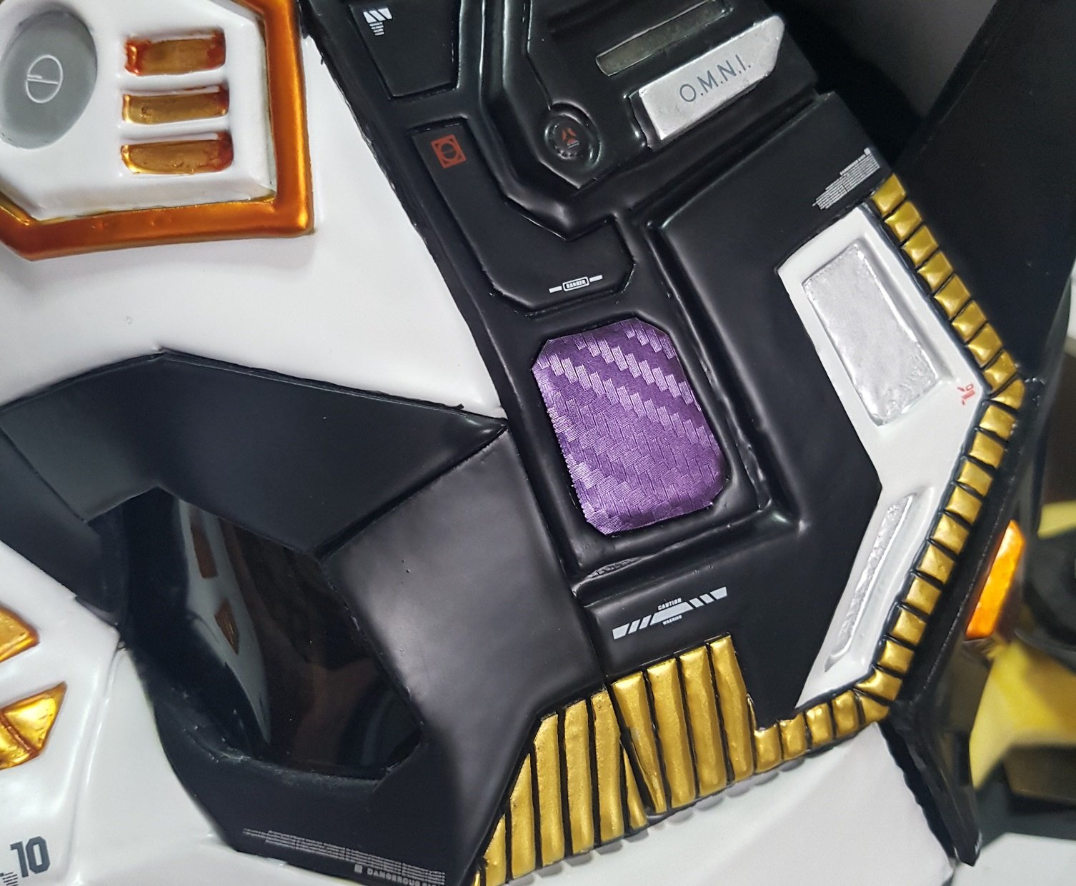
For the appearance of the head, lastly, it was sealed off with two thick coat of samurai lacquer spray paint and then airbrushed with a model grade matte clear coat to remove the shine from the lacquer paint (which is too glossy and look like it is a plastic toy.) small details like carbon-fiber vinyl were sticked to the side of the head to finish it off and gives different texture to the dog head.
After Samurai lacquer spray
Carbon-fiber vinyl after airbrushing the matt clear coat
The process of making the head from start to finish was long, but I’ve learnt many skills as this was my first time using EVA foam, so everything was a good lesson, even from the small details like “how to cut EVA foam properly” is an invaluable lesson for me. And throughout this process, I also learnt that what materials could or could not go with the other, and also how to cause the paint to stick onto the resin firmly and not peel off.
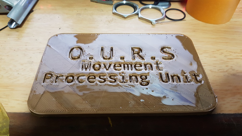
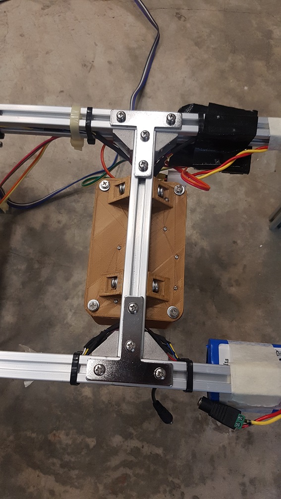
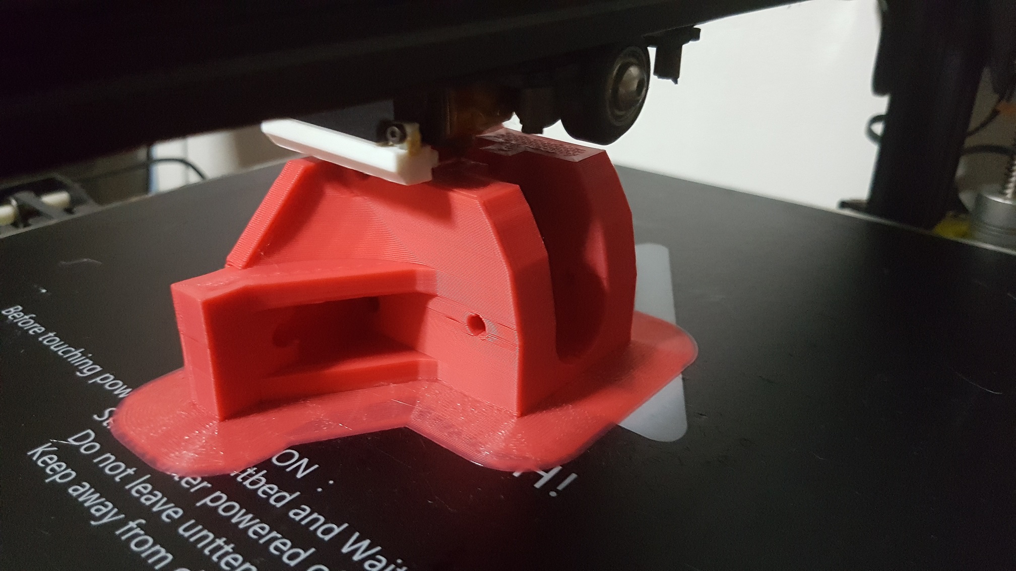
3D Print + Resin treatment as I want to see the effect of applying Resin to 3D printed parts, It was airbrushed with gold paint afterwards to test the paint holding properties of resin, which to my surprise, is good!
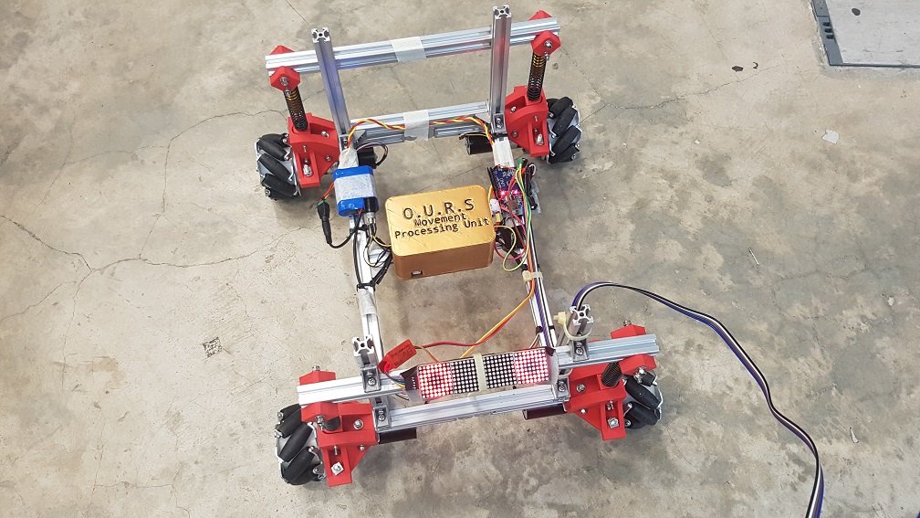
after attaching it onto the base of the Robot, this case serve as a protection of accidental dislodge of the pins (while still maintaining the function to switch out the board) from the arduino as well as adding a slight water resistance to it,(you never know if the visitor will drop a cup of water onto my robot during the show)
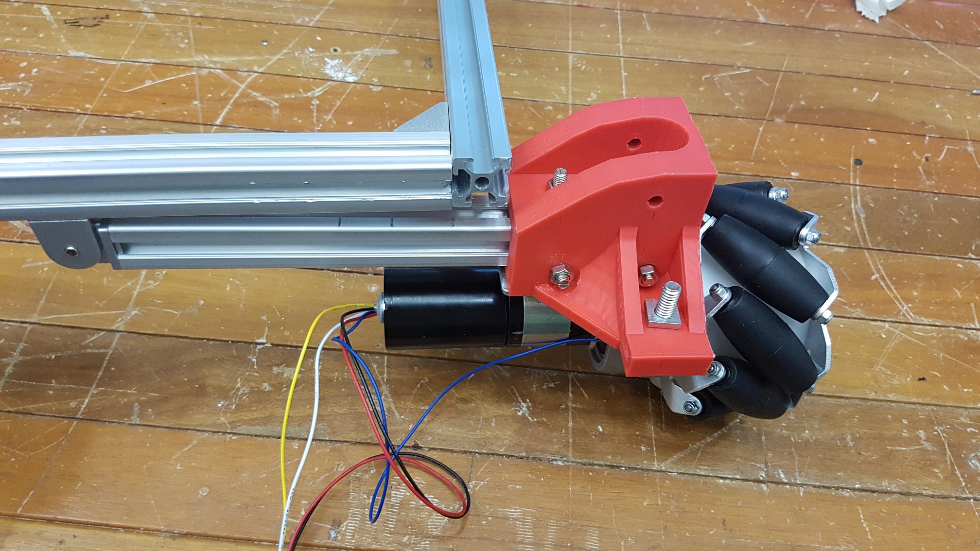
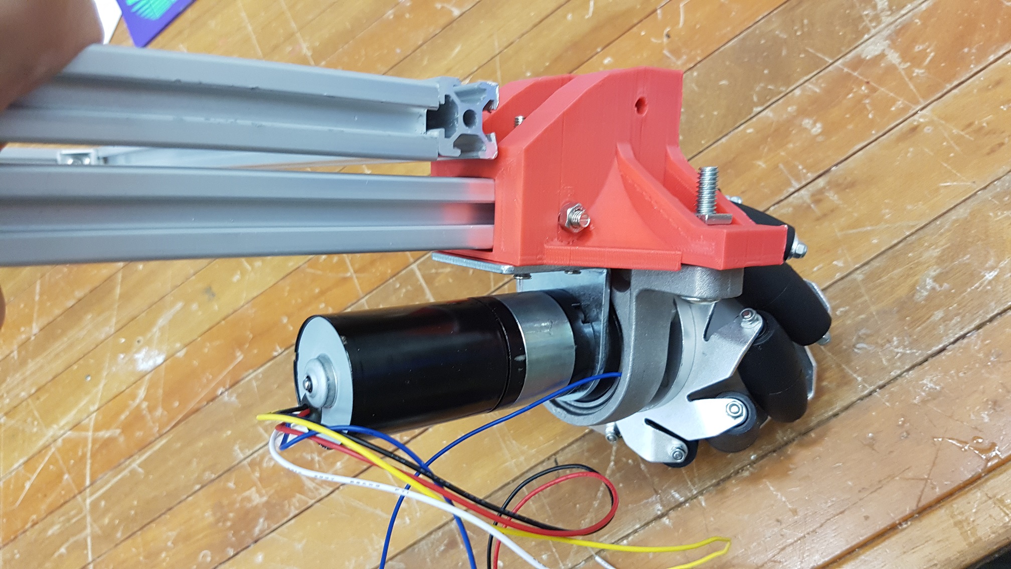
Parts Strengthening to make sure nothing come loose:
original connection of the aluminium profile. 4 screws with spring washer at each connections on the 90 degree joint.
added a T plate to secure the joint, total screws with spring washer = 8, and it is structurally stable (the screws hold all axis of vibrations.)
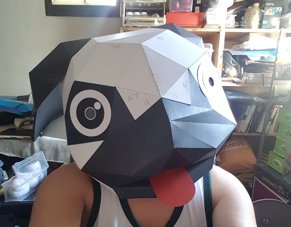
Experimental Head for the robot:
3D Paper Model, cut them and stick it together
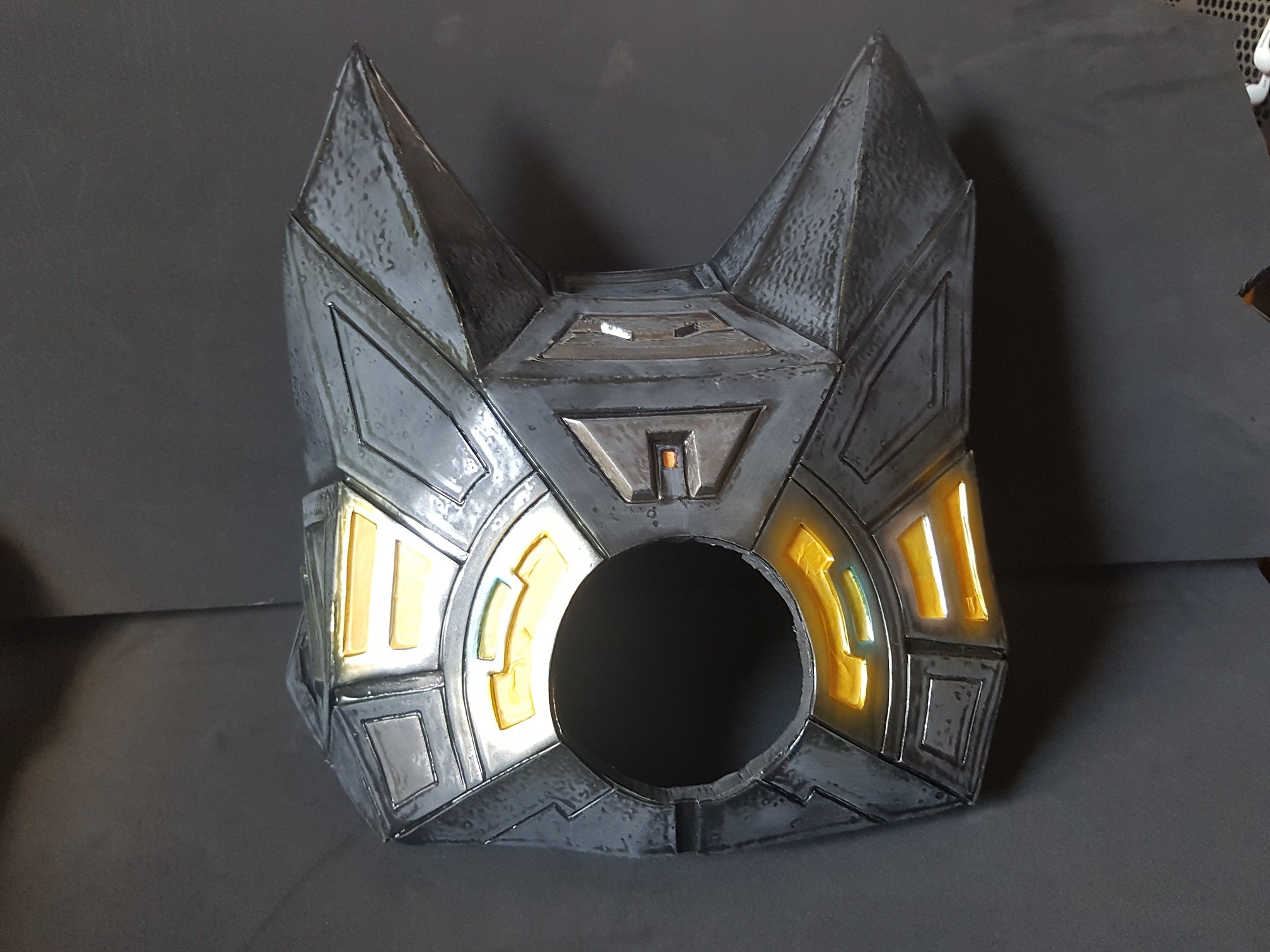
Dog head. Why a dog? because dog is human’s best friend and you’ve heard of search dog, guide dog, which is exactly what my robot is about, and it is cute.
after cutting the eye out and replace with the LED matrix with arduino nano. i would say it made it really interesting to look at just with the eye that moves.
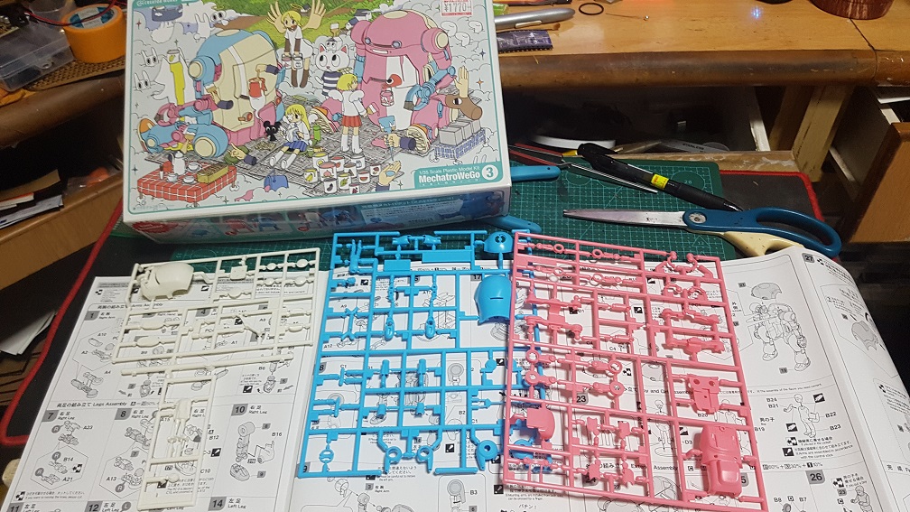
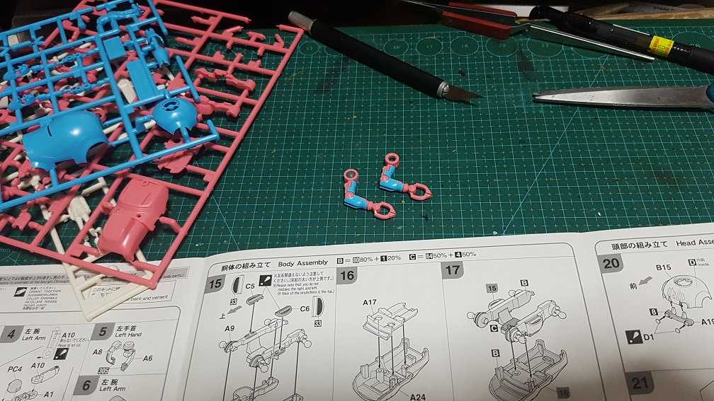
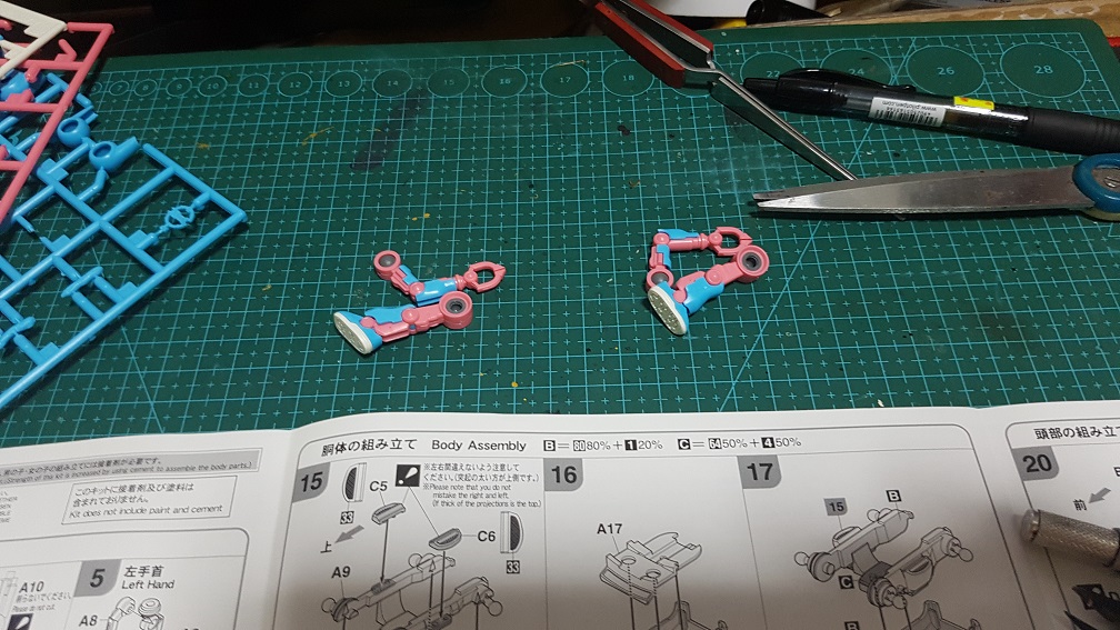
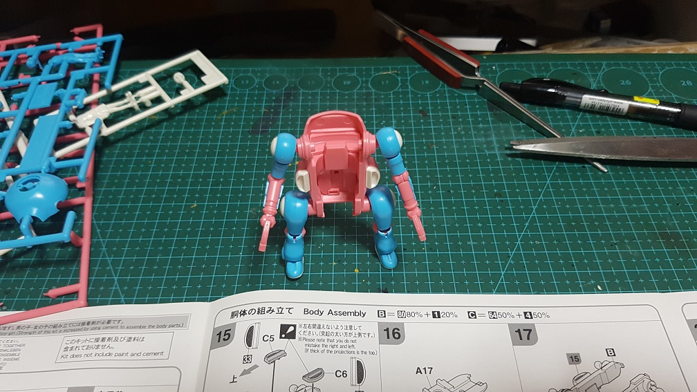
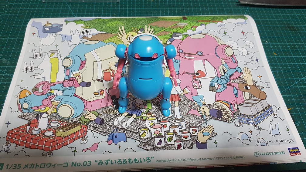
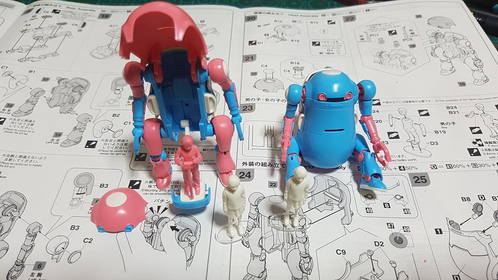
Plastic model building from the Japan Research Trip:
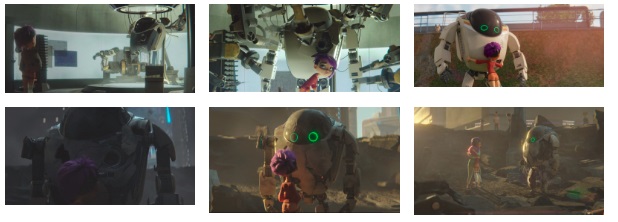
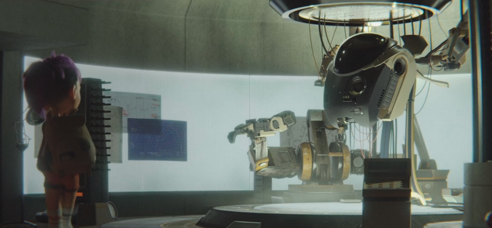
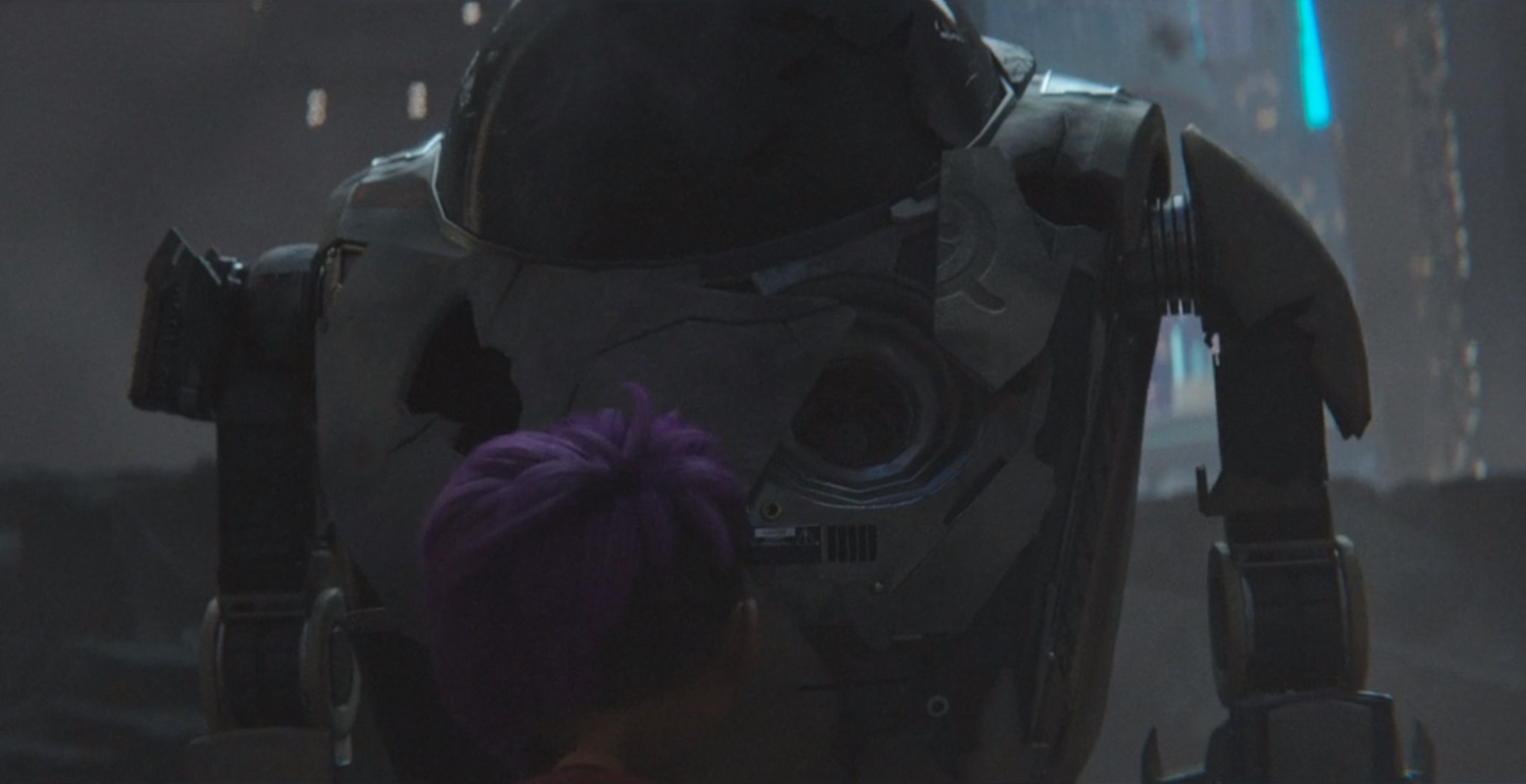
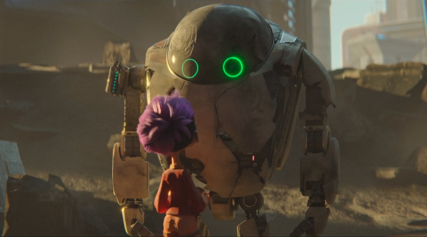
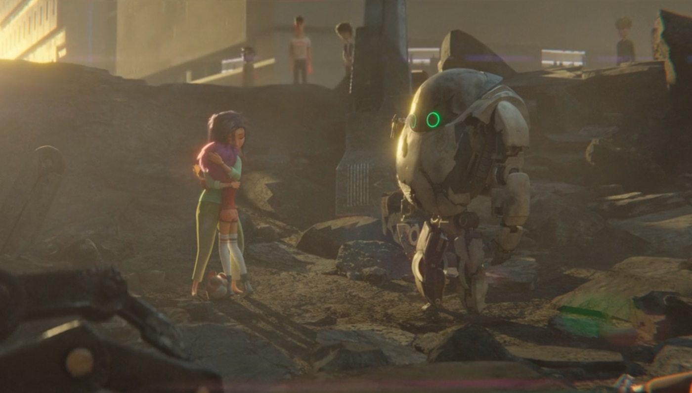
These are the show I watched in the past 2 weeks to get ideas for the robot personality, appearance concepts, and the overall world for O.U.R.S..
next gen:
This is the nearest concept to what I have in mind, from the robot characteristic, appearance, to the overall concept. the Lab scene, the destroyed appearance is what i could reference on and I really like it.
Final space:
The personality of KVN(Kevin, the round robot) of this show got some really interesting personality, it is really irritating and have some sense of self realization that it is easily replaceable was really cool.
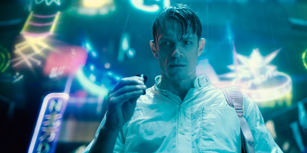
altered carbon:
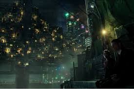
watched to get a general sense of a cyberpunk theme(which is the world O.U.R.S was placed in) really cool technological stuffs here and the city was really well made.
dragon pilot:
Dragon + Robot, quite cool, except for the fact that the anime was good, there was nothing much for me to reference here.
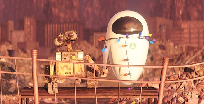
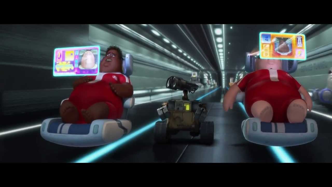
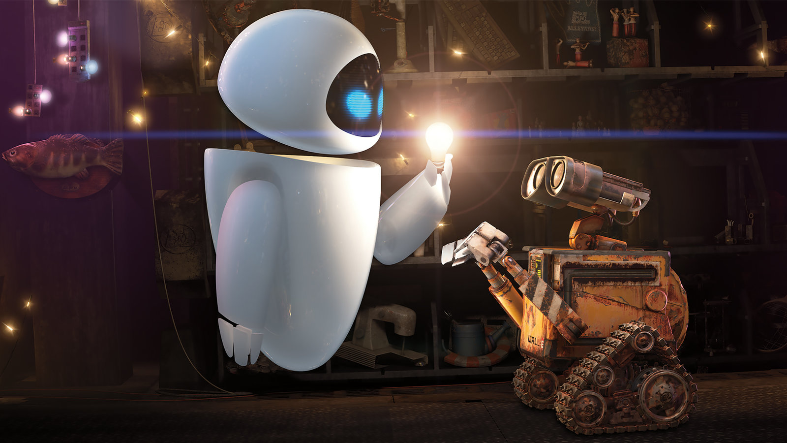
Wall E:
classic, robotic sound can create emotions too, simple movement and eye from the robot could say alot.
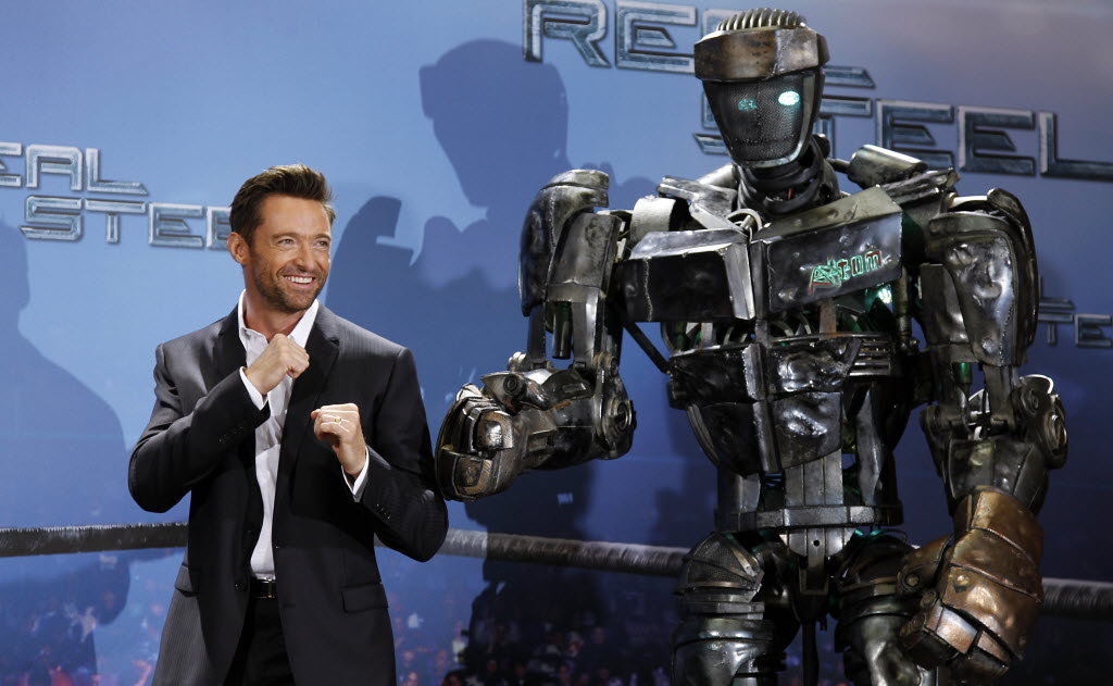
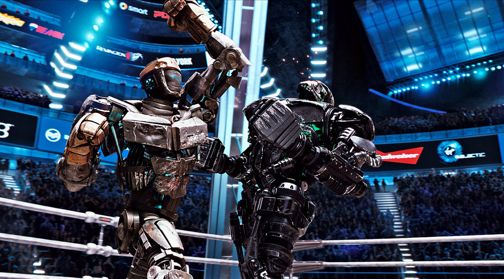
Real Steel:
it is just an action movie with robot, nothing much here.
current Art Direction for explorer 27:
Friendly, empathy, not industry looking, not intimidating.
BY 26 OCT :
unity + touchscreen control master arduino
read book (I robot – Isaac Asimov)
By 9th nov:
drawing for concept
lidar(maybe)
head model (maybe)
Further Research Done:
“Mobile Robot Planning to Seek Help with Spatially-Situated Tasks
Stephanie Rosenthal and Manuela Veloso
Computer Science Department
Carnegie Mellon University
Pittsburgh, PA 15213”
These 3 were drawn in Adobe illustrator in separate layers and imported into unity to animate it.
Lidar:
Lidar uses infared laser to sense the distance in a 360 degree manner, it could give thousands of readings per second and the program will calculate them and map it out through a point cloud.
when using the program that was provided, the lidar works perfectly, but since I am going to use it in Unity, there are problems as Unity runs on C#(a programming language) while the SDK(Software Development Kit) runs in C++, although it is not impossible to write a bridge between the 2 language or write another code in C# to use the Lidar directly in unity, it was out of my capabilities to do so after trying for a week, and while researching for how to do it, i came across another Lidar that provided the Unity codes, however the code does not work on the current lidar I have……
SO, simple solution to this problem, either i ditch the idea of using a lidar OR I buy the Lidar with the Unity code and I put the current Lidar I have for sale online (at higher price than I bought it of course.) And of course, I chosed the 2nd option, to sell the one I have and buy the other 1 that provide a unity code. Carousell, my best friend.
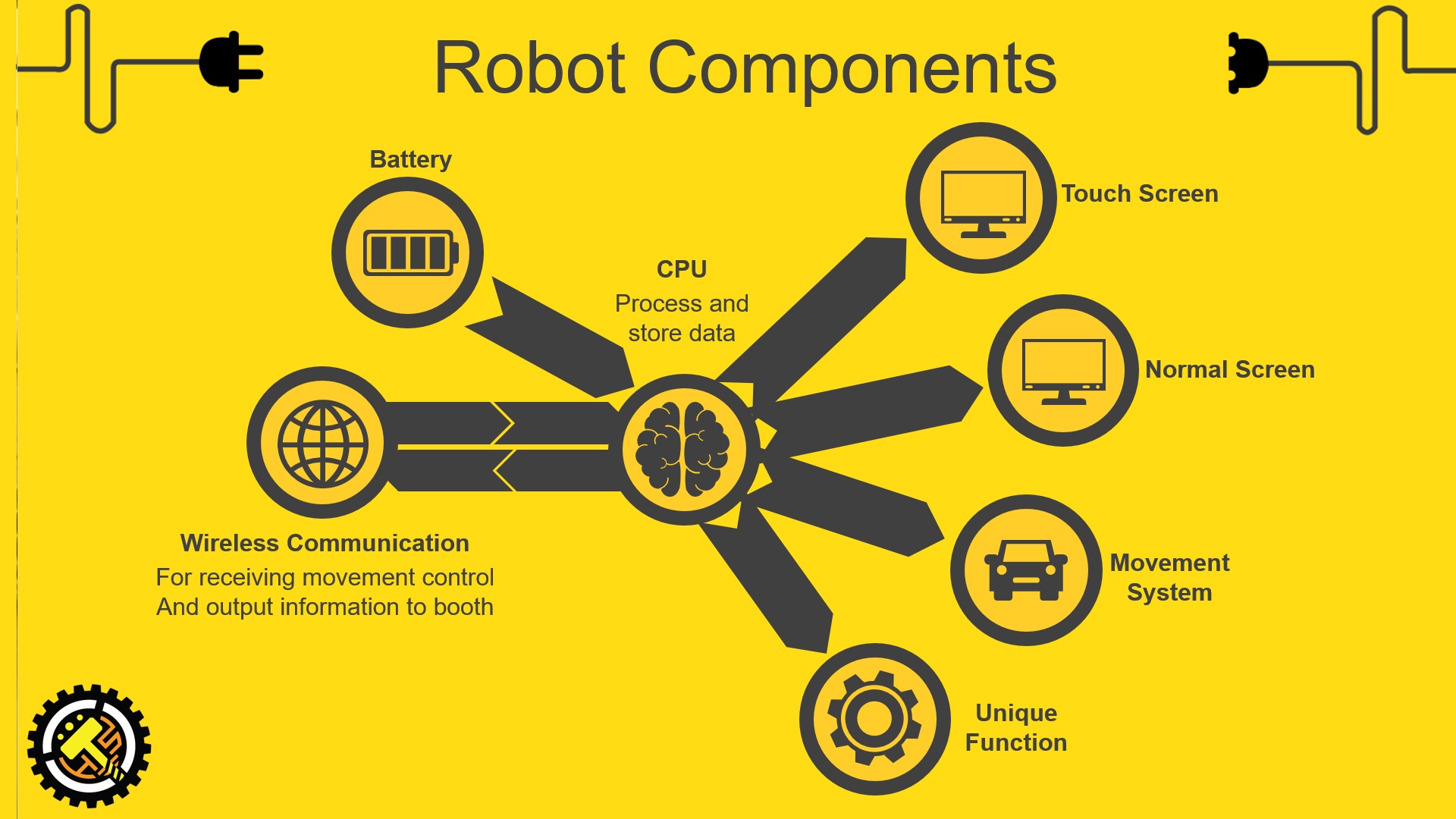
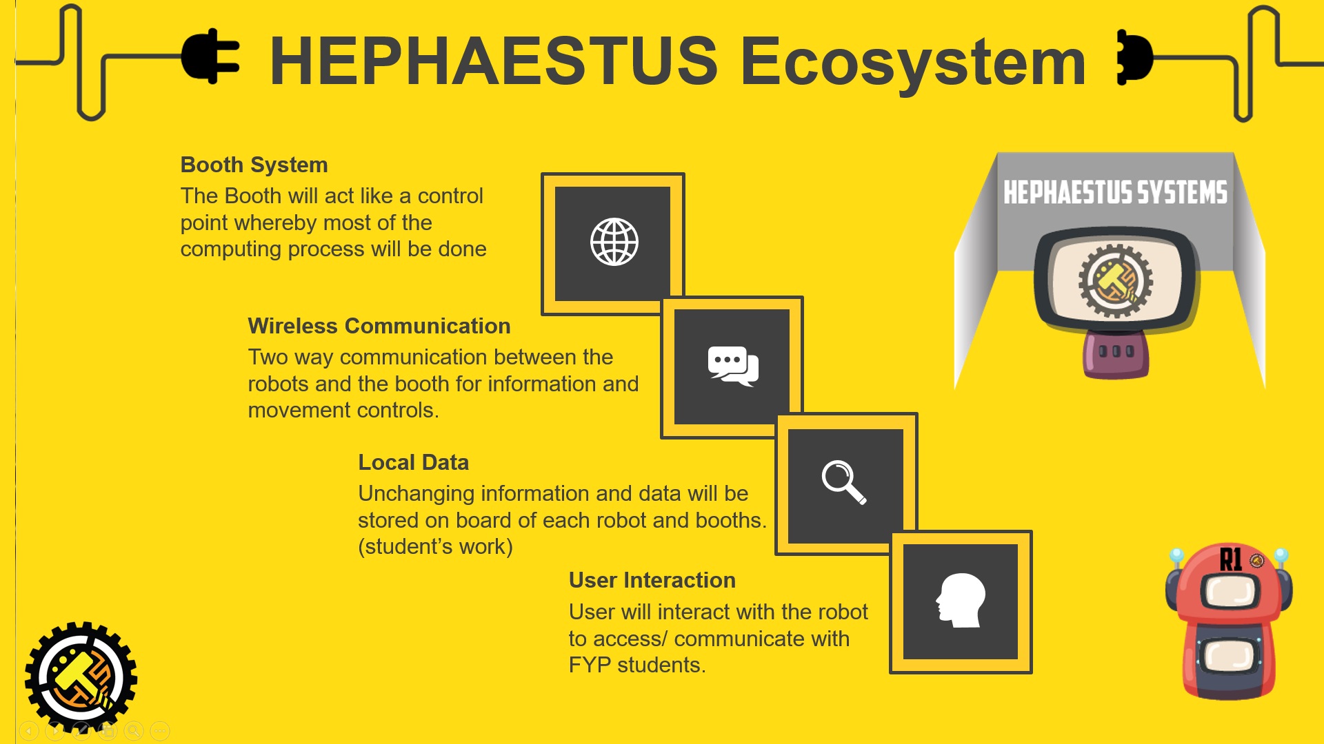
Hephaestus system is a set of 3 roaming robots and a booth, these robots will be specially designed with different appearance and function to provide addition showcase platform and information of all the FYP students (except for me), visitors will not get any information of me from these robots. Only the booth will have information of me because, really, I have to find some place to put my name card. And it is kind of cool for the visitor to realize by themselves that the robots is a work of a student. Another reason for the robots not to show my work is to prevent conflict with my peers, since my robot will be walking in other major’s “territory”, it is simply not nice to broadcast my own project.
Imagine one day when you are lying on your bed and receive a SMS telling you that your FYP project is awesome? how great is that?
Imagine what can the system do for product design student if there is holographic display on one of the robot? You will see the student’s information on the main screen and the student’s work in hologram?
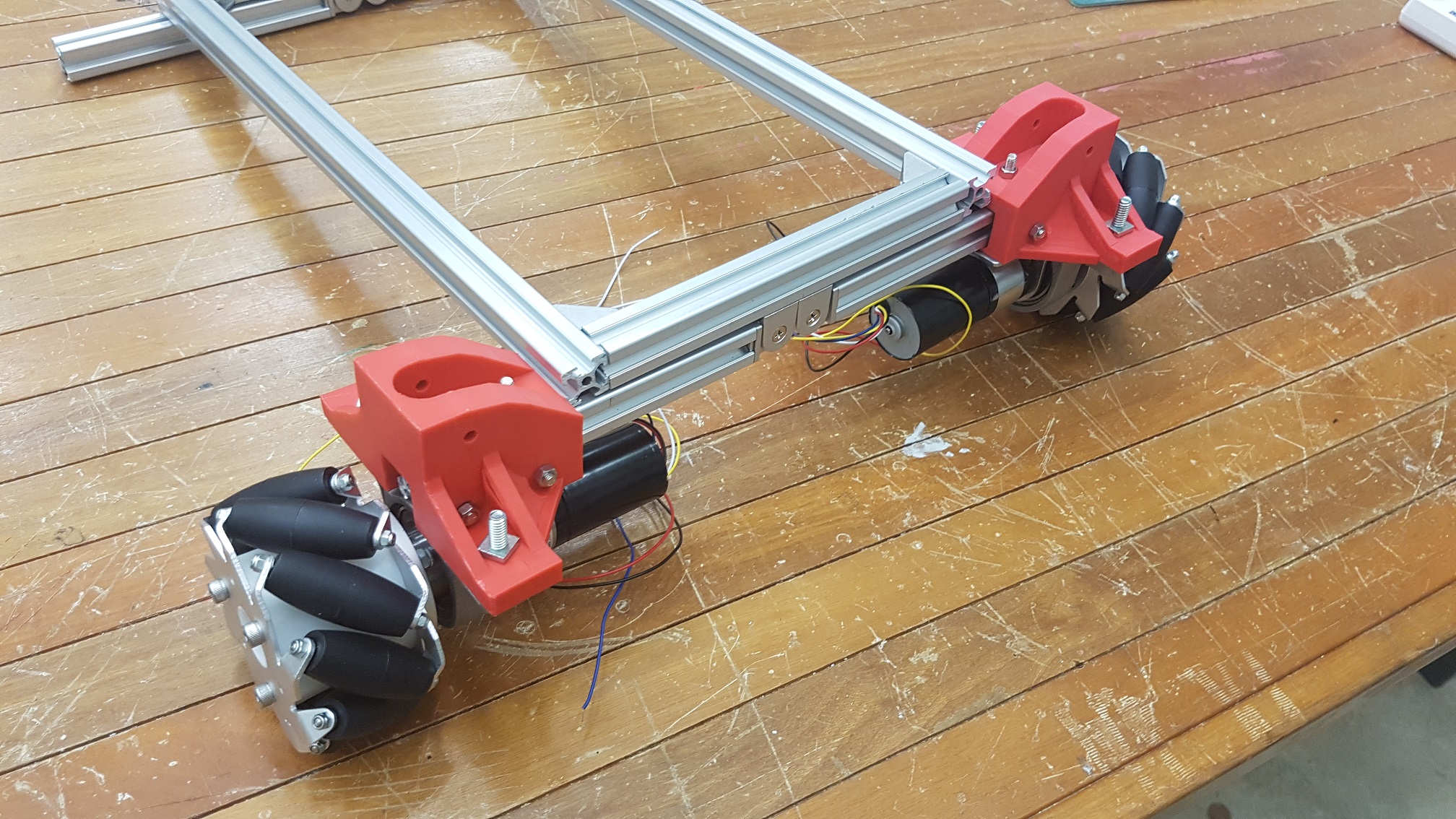
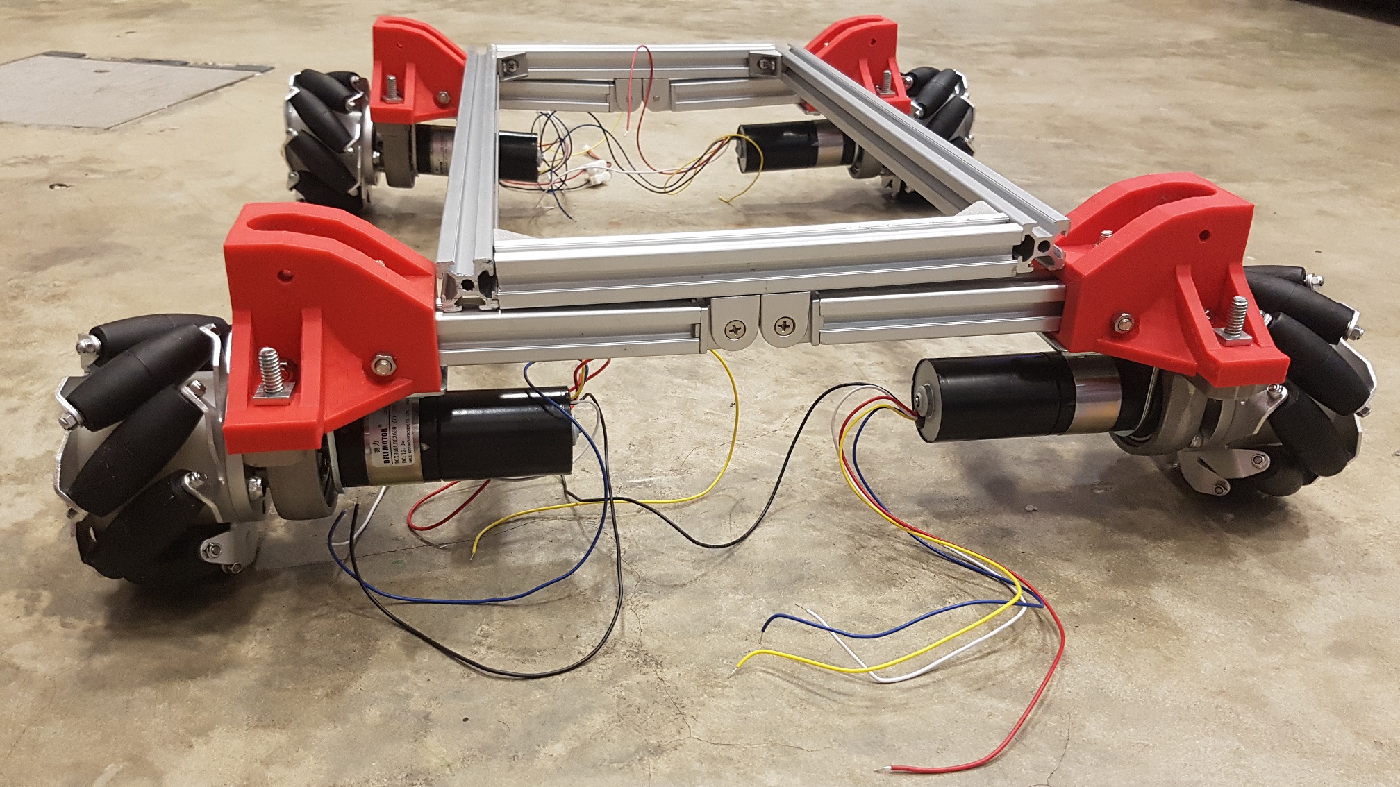
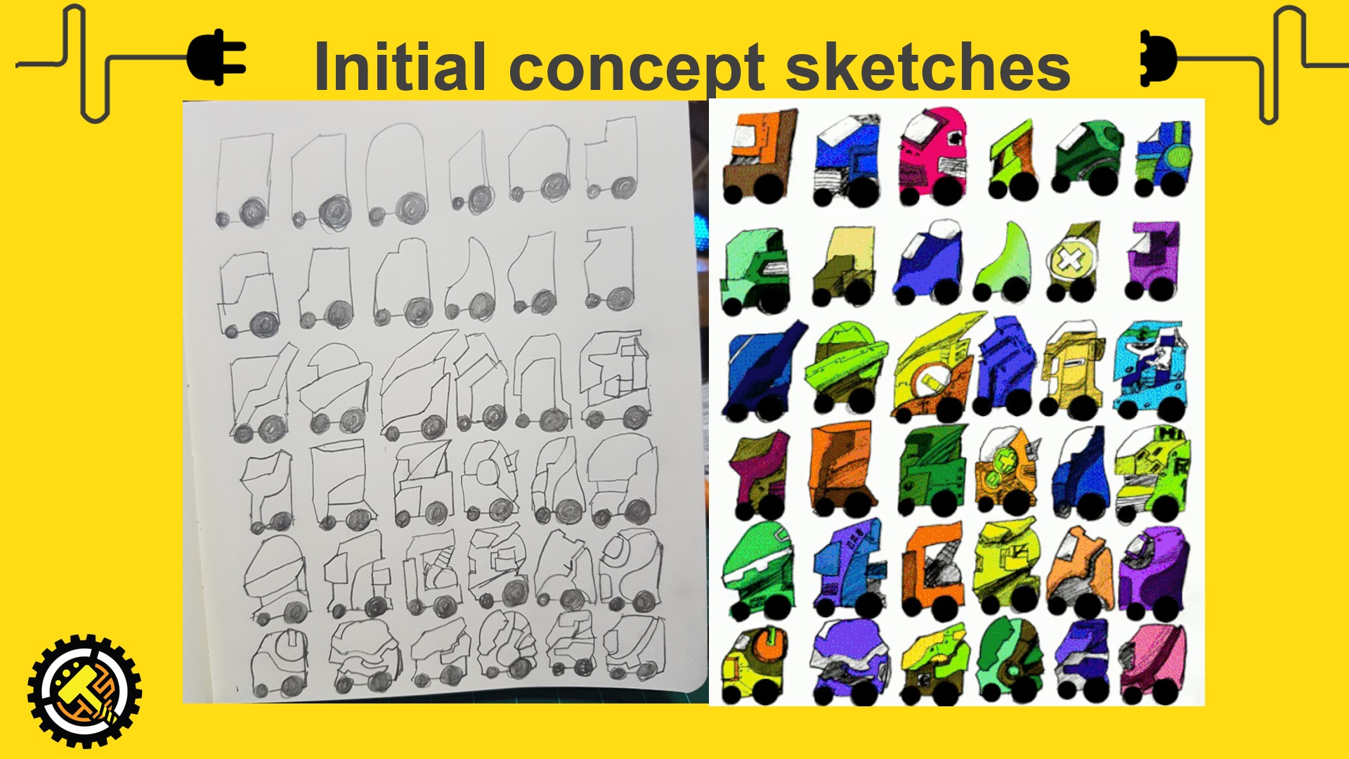
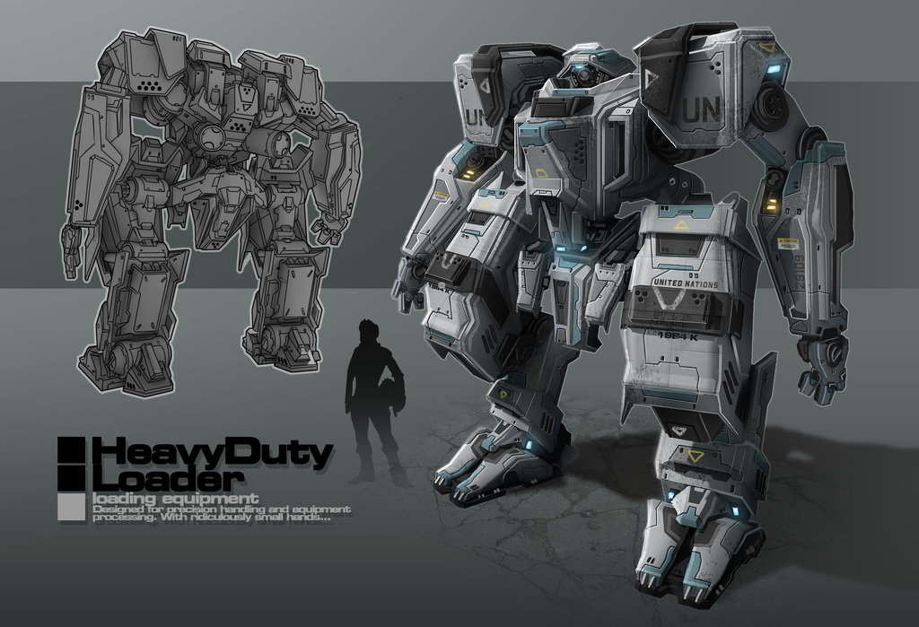
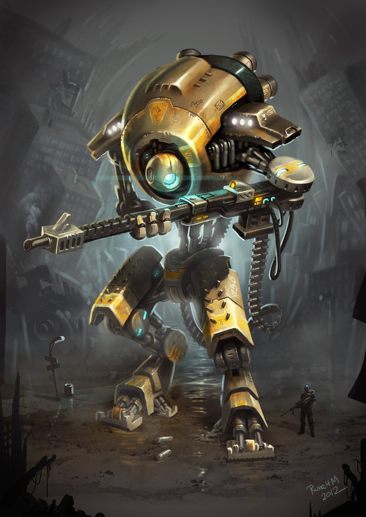
Slightly more detailed drawing of the one that I like the most out of the 36. this will be the rough gauge of the size of the robot
The final robot will probably not be this, but this is a good gauge to show the overall style of the robot which I will be making, not those typical looking or DIY homemade robots.
show the remote control proof of concept i made.
Computing done in the booth system as it will be connected to power supply and heat will be dissipated more efficiently than in the robots. Current location of the robot and movement control will be sent from the booth, user input and message will be sent from the robots to the booth.
Intended recipient and message from user will be transferred from the robot system to the booth through wireless (Bluetooth or Wifi), Booth receive the message, encode it with the recipient’s phone number into the GSM module and send the message through a prepaid simcard.
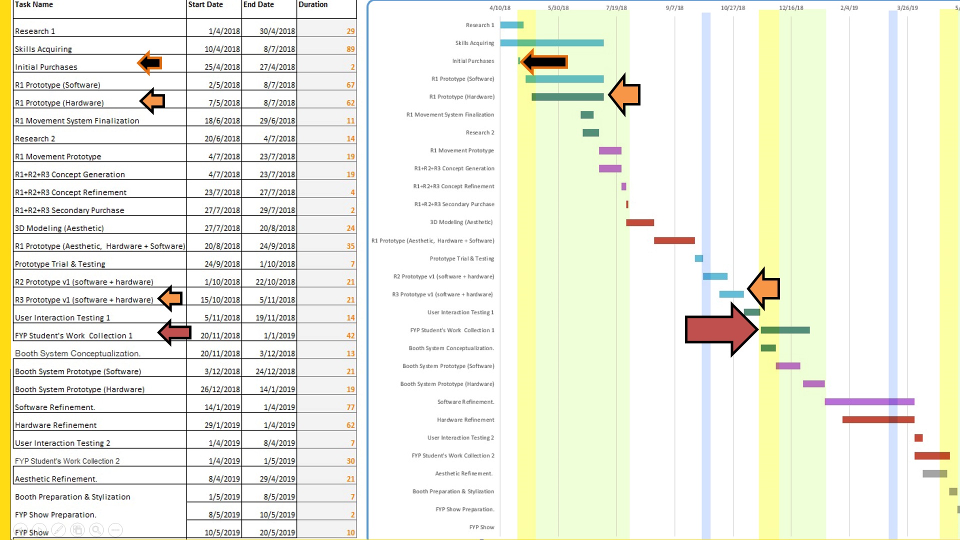
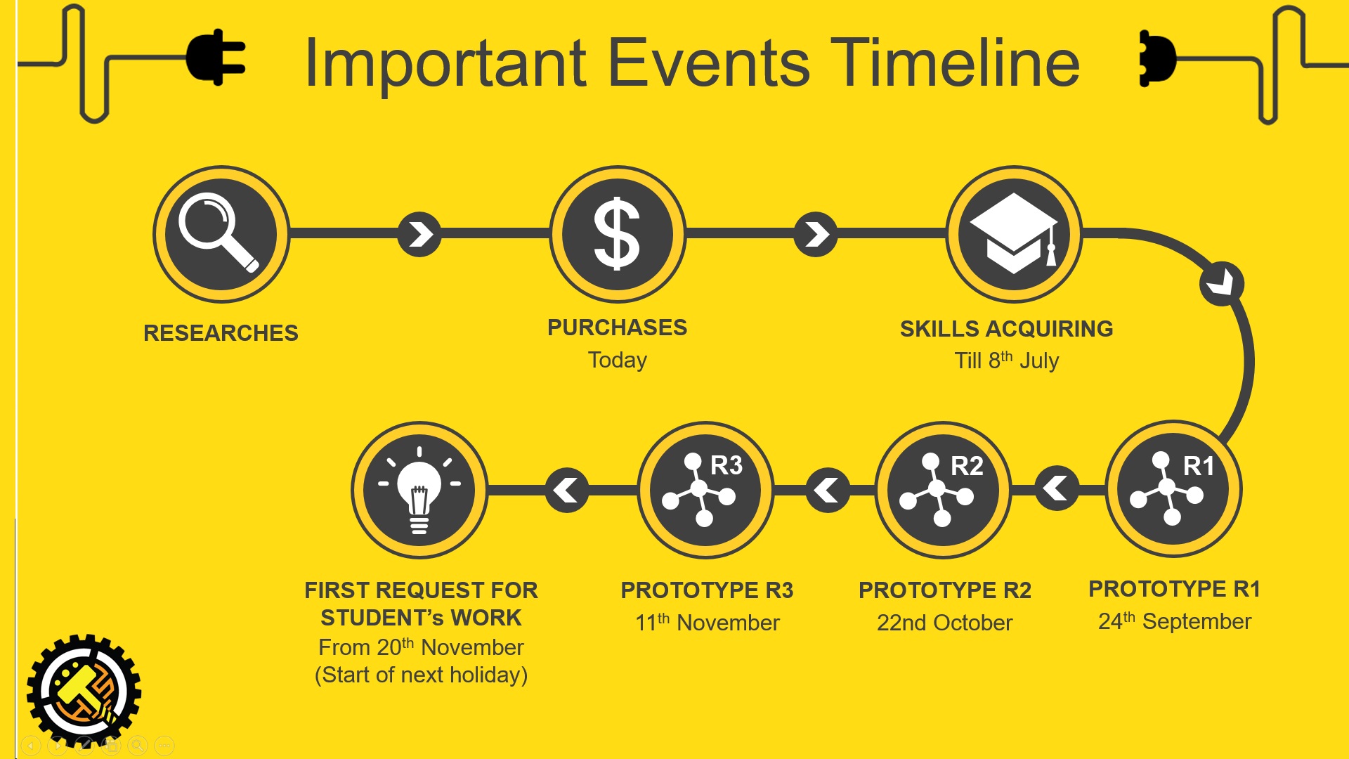
Skills Acquiring and Prototype R1 goes hand in hand, I will learn while doing and do while learning.
As of now, there are many skills which is essential for me to achieve this project but I don’t know, so I will be learning them. Blender is a 3D modeling software, it is really powerful and the best part is that it is free, the downside is the learning curve is really steep.
continuation from the previous part 2 post with some new ideas after the talk about the past FYP showcase from Assoc Prof Laura Miotto, I’ve been inspired to do something that focuses solely on the showcase, since the showcase will mark the end ADM life of all current year 3, I would like to do something for many of the peers that would enhance student’s FYP showcase capability as well as the visitor’s experience of the visit.
As the founder of Kimchi and Chips, Elliot Woods asked during the Emergent Visions Symposium,
“What is the work that only I can make?”
This question hit me like Tiger Woods golf clubbed me in the head…
Yes, what is the work that only I can make in this coming FYP showcase?
back to my first post, I’ve already know what my strength is at this point of time, I would really want my FYP to have an impact on others, why not use my strength into making other’s FYP presentation to potentially having slightly more possibility? Wouldn’t that be great?!
so, this will be an idea which I know that I would enjoy spending a year to complete.
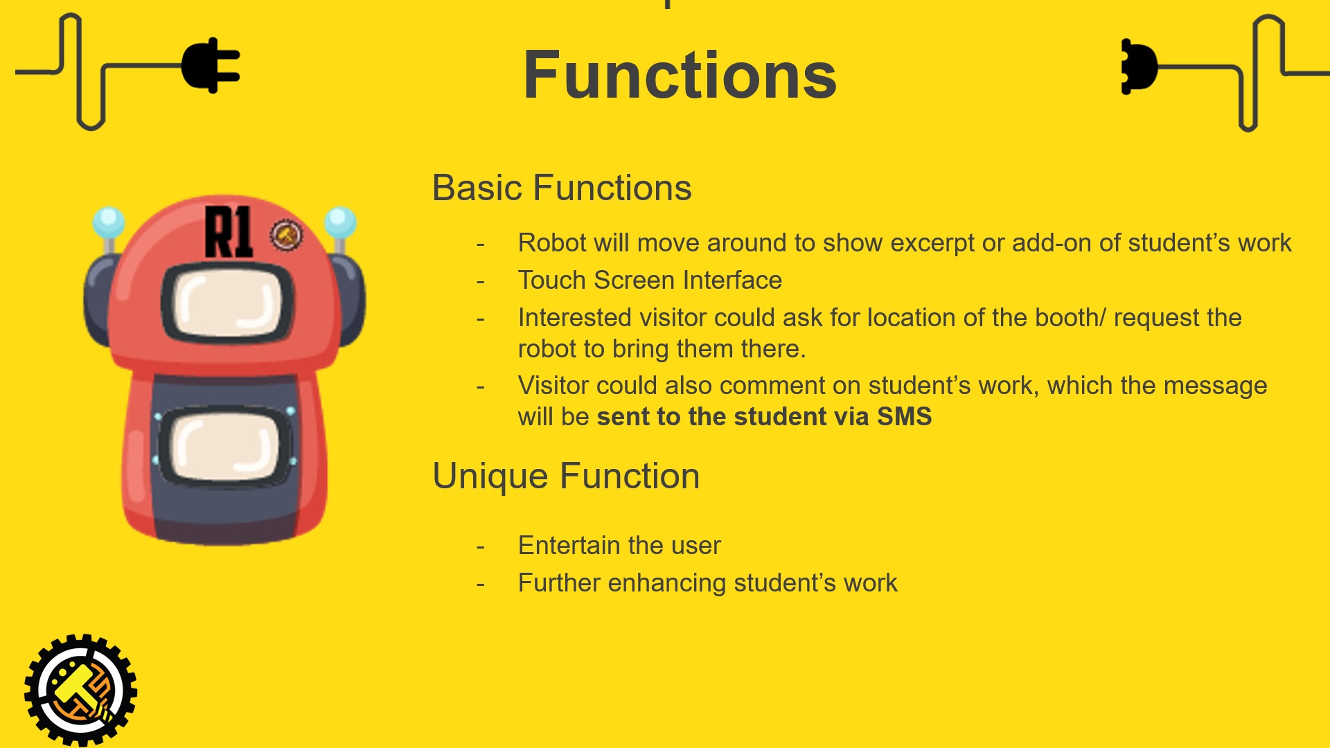
A set of robots(3 to 6) that will display student’s work in complementary of their booth where visitor could get more information(project info/booth location).
Just imagine, every student have their booth while a robot moving around in the FYP show displaying their project on its screen, when a visitor saw it on the screen, got interested and wanted to see the booth, they simply click a “Bring me to this booth” button and the robot will do so. How much more potential exposure will that bring to that student?
And on another aspect viewing this project, what will be realer than an actual application of an FYP project during the FYP show? What the visitor sees is what was actually made specially for that FYP show, if it doesn’t work or spoiled halfway, it simply meant that I did not plan well/have a backup or do a good enough job but there will not be an imaginative scenario where “This FYP was supposed to work in another location” *I am not saying that that kind of project isn’t good, but just what I would not like to do*
Project Brief ver.1-
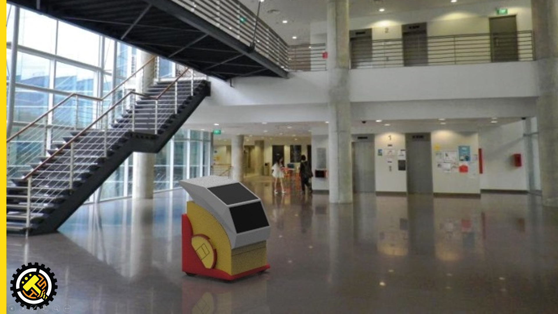
To design a set of Robots that have the ability to move around while avoiding people/obstacles during the FYP show. The purpose of the Robots is to expand the presentation possibility of student’s project while enhancing the experiences of the visitors. Safety of the people around the robot should be of the utmost importance and under no circumstances whereby injuries caused by the robot should happens.
Project Specification Ver.1 –
Each Robot should have a minimum battery life of 6 hours on single charge.
Every Robot designed should be unique and serves different function.
The Robots should be designed with ease of maintenance system that allows ad hoc repair.
The interface on every Robot will be touchscreen enabled to suit the behavioral characteristic of the targeted user. ( young adult of developed country)
Network between Robots and a Central Hub should be setup to enable a smooth flow of communication and for controls during the exhibition.
Similar Project :
Although it will be really hard to do so, but I aimed to complete a project of this standard but the task which my robot will do is much simpler.
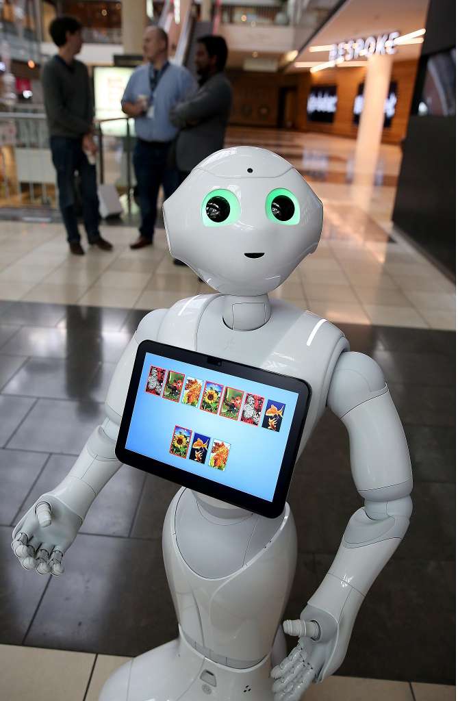
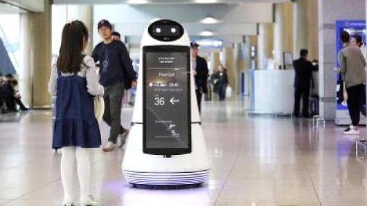
Moodboard:
this will probably a good gauge as a robot size which i will build.
of course, the screen wont be so big as the price would be expensive.
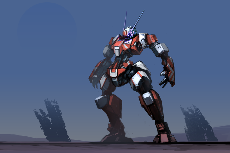
468_999 by ksenolog.
I like the colour scheme of this type of robots,
bot by operion.
Although it is rather dark here, but the top simplicity is rather cool.
bot concept design by chriss2d.
I might build a similar robot like this minus the limbs.
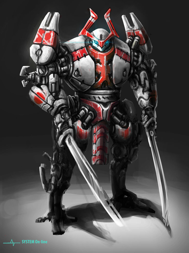
samurai bot by andynd.
Colour scheme.
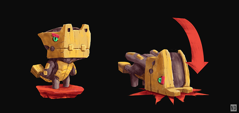
catsbot by trudsss.
colour scheme and friendliness
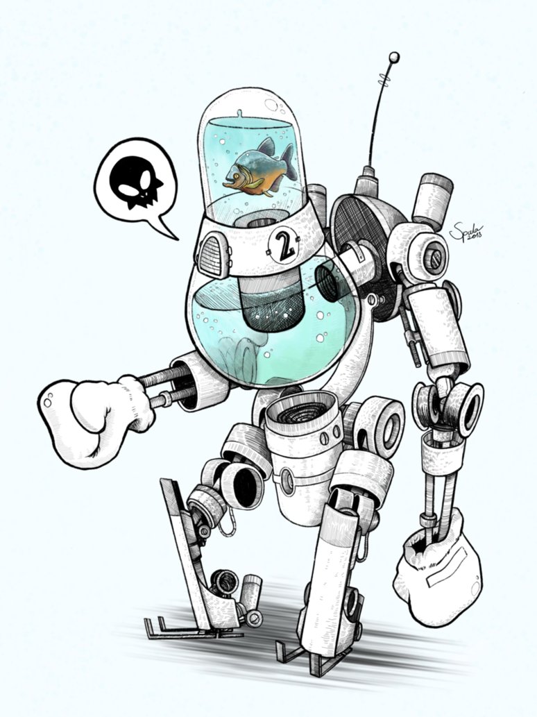
fishboxerbot by hubertspala.
unique design that is out of the box.
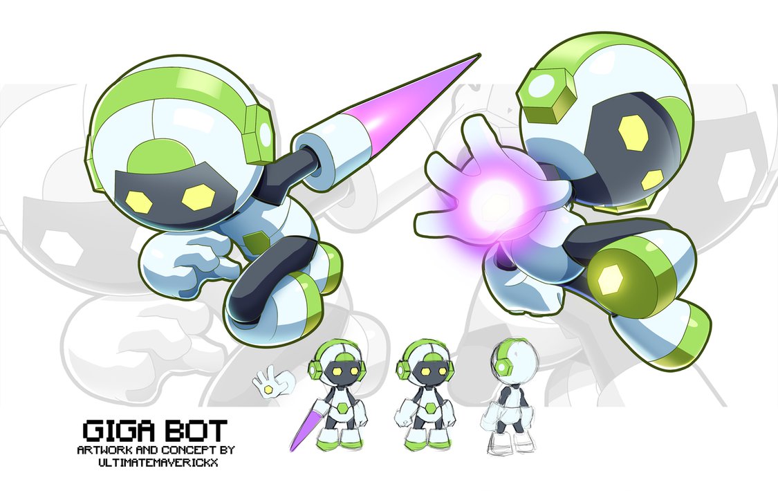
giga bot concept by ultimatemaverickx.
colour scheme, + shape
hammy the hammer head by andynd.
I really like this cute robot and simple shape
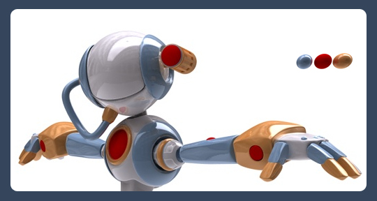
hdri bot by ethan.
Shape.
kuning bot by adry53.
Colour scheme
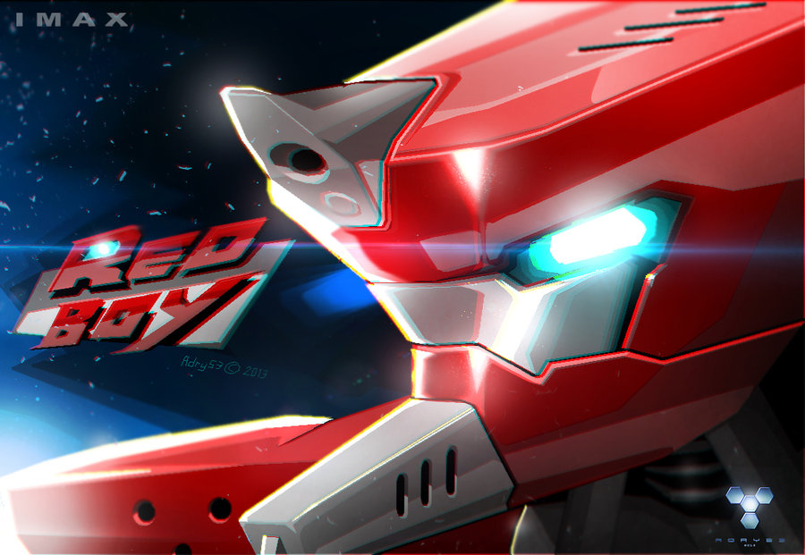
red boy by adry53.
Colour Scheme
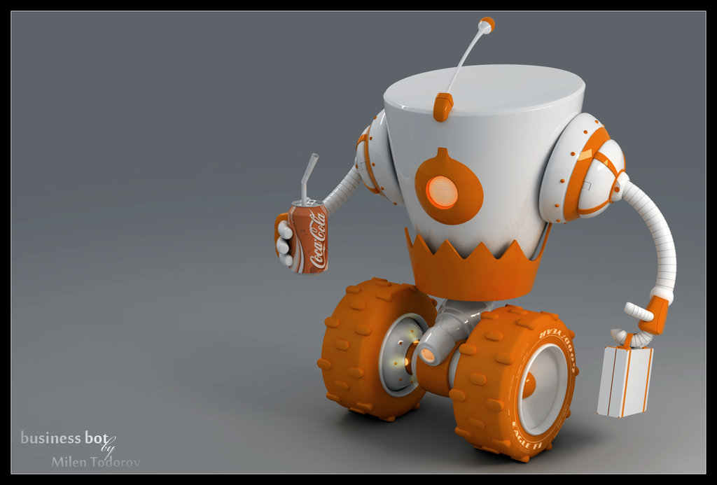
business bot by milenplus.
Colour scheme + the overall friendliness aspect seemed similar to what I have in mind.
mean frog by glaaarg.
cool robot like this might be nice too.
mech 3 by astrokevin.
overall presentation of a poster-like layout will be good on my FYP booth,
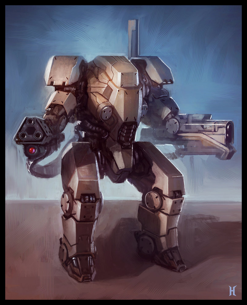
mech by nemanjas.
mech suit by flyingdebris.
Overall shape and details minus the limbs
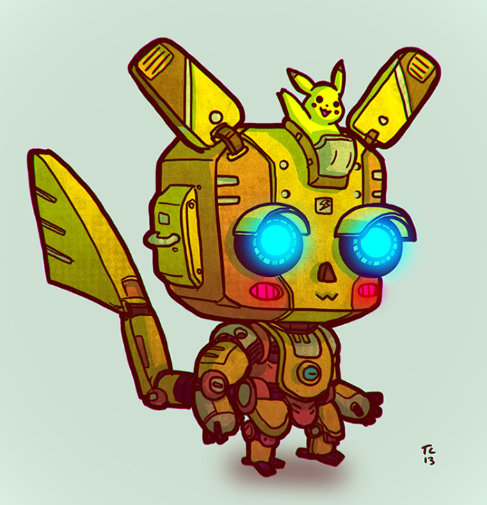
mekachu by trudsss.
Colour scheme and cuteness.
mobile memory unit by tehan.
I like this and the idea in which the walking camera is a “Mobile Memory Unit”
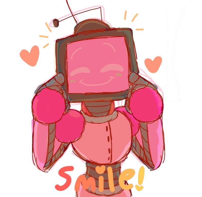
remember to by inkgummi.
overall feeling + the screen head is nice.
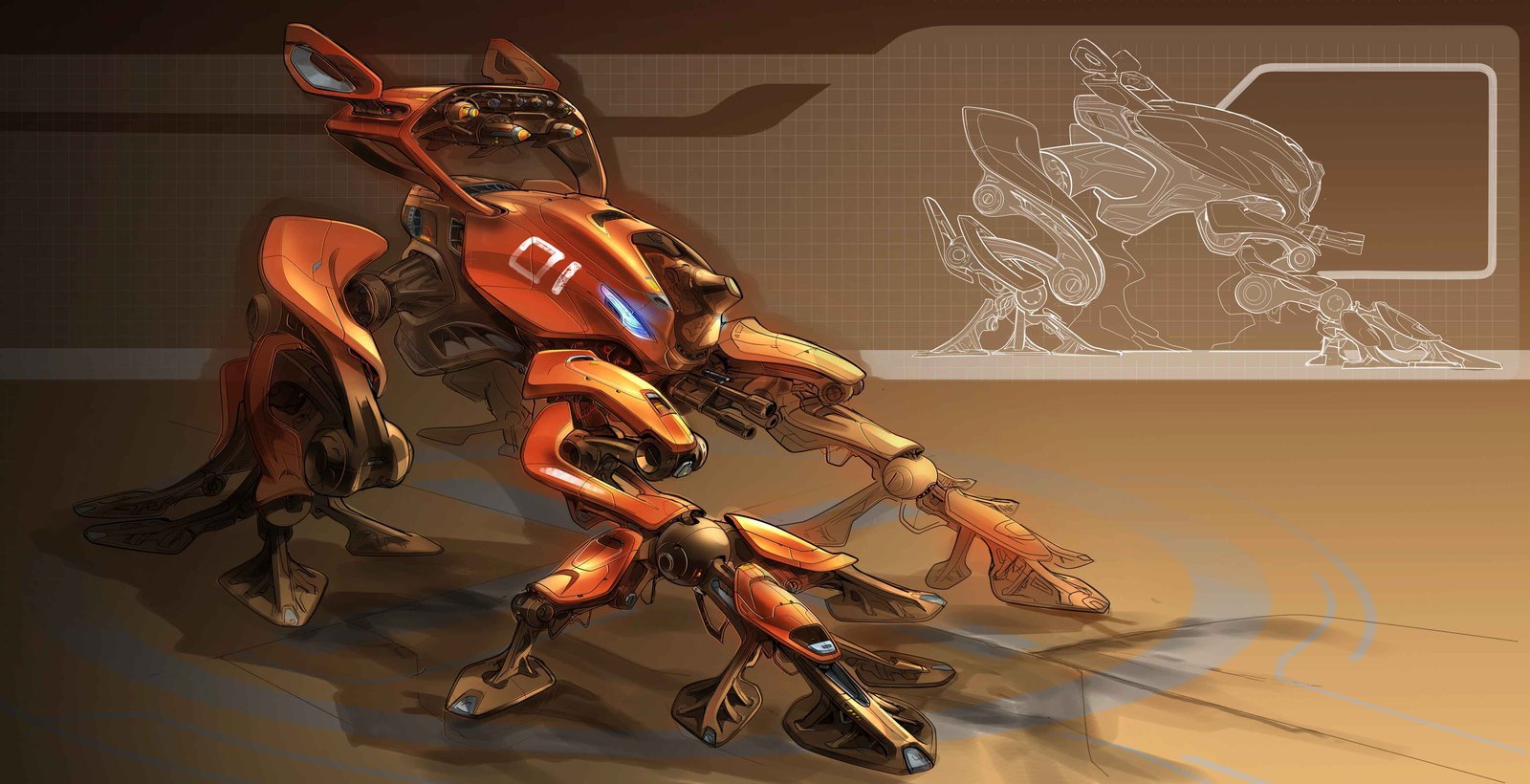
robot by ahmadturk.
Colour scheme+ details + shape.
sir crow by trudsss.
Cuteness and the robotic like armor with organic head.
sniper bob by boxer18.
details + colour scheme.
Computational System Research:
There were many considerations made for this aspect of the project, firstly, the Cost and Value Analysis of the system must be made, of course, if money isn’t a problem, then this part would be really easy as I will just get the suitable parts which I need for the FYP, but sadly that isn’t the case… Money is a problem in FYP.
So, how can I maximize the output of my project by using the minimum amount of money? I have to also consider about how strong/fast the system is, and how would I like to have the user interface (touch screen) to be incorporated into the system.
These are the types of computation system which might be possible for my project at reasonable price –
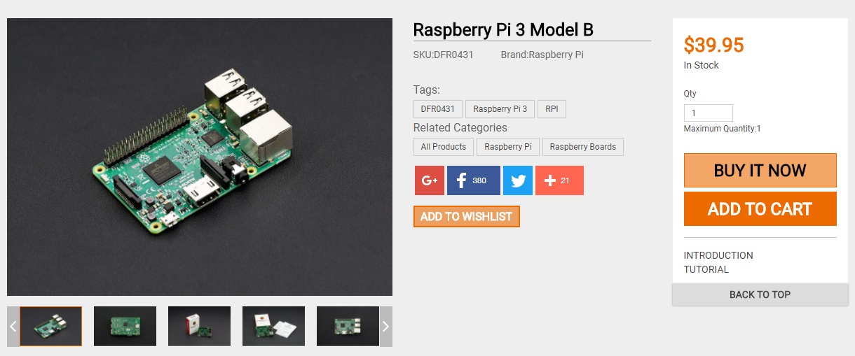
Raspberry Pi 3 –
This is the latest Raspberry Pi 3. It features a 1.2GHz 64-bit quad-core ARMv8 CPU with 802.11n Wireless LAN and Bluetooth 4.1. Like Raspberry Pi 2, it also has 1GB RAM,4 USB ports,40 GPIO pins,Full HDMI port and Ethernet port. This third generation Pi is an excellent tool for hackers, makers and educators because of its small footprint, low power consumption, and low price.
Pi 3 comes with build in WIFI system so that would save me about $30 for WIFI module, output of screen is easy to setup(like a normal computer), runs on Linux system, which I have a slight experience on and as a bonus, I own one of this so that would save me some money too.
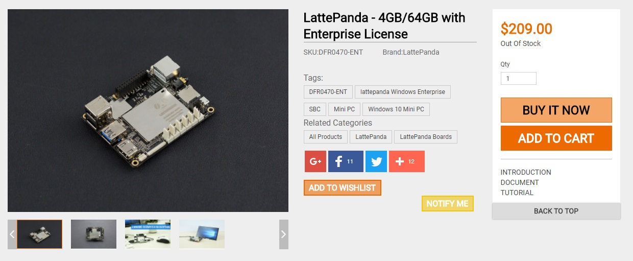
Latte Panda –
A LattePanda is a complete Windows 10 single board computer. It has everything a regular PC has and can do anything that a regular PC does. It is compatible with almost every gadget likw printers, joysticks, cameras and more. Any peripherals that work on PC will work on a LattePanda.
In terms of processing strength, completely overpowered Raspberry Pi 3, the price is however much steeper than Pi 3, also as an added bonus, I already own a Lattepanda and I would rather work on Lattepanda over Raspberry Pi as it runs on Windows system and that would save a huge amount of time for me, plus overall it is much faster at processing video and even runs Max MSP(a programming software) which is what I will probably be using. I am sure Latte Panda will be more responsive than Raspberry Pi 3 at the cost of more $$.
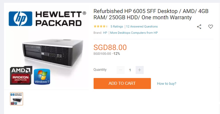
Cheap Desktop CPU –
Yes, I praised so much about Lattepanda, but the cheap CPU nowadays is already cheaper than a LattePanda, although bigger,heavier and more power hungry, it is way cheaper than a Lattepanda at relatively same processing power and also, a cheap CPU usually comes with Internal HDD(atleast 128GB) while Lattepanda only has a mere 64GB(minus operating system installed, leaving about 40GB). Best part, Desktop CPU comes with built-in cooling fan, which overheating is a problem for Lattepanda.
*REFURBISH is the word here hence the cheap price*
since I don’t really need a brand new computer to get the job done. This is the normal sized CPU, which is rather big but I am sure it is small enough to be build into a robot.
Second handed/refurb touchscreen laptop –
For me, I think that this is the best system i could think of for now which I will need, firstly, touchscreen laptop meant that I do not need to purchase another separate touchscreen(which is usually really expensive) secondly, it comes with all the benefit of a CPU like cooling fan and such, also, laptop have a additional battery which reduce the load of the power supply, like if the main power supply ran out, there will still be time for the system to send out notification to the control system which then battery could be replaced. lastly, laptop will be slightly lighter and uses lesser power in comparison to a CPU, which make it really good over a normal CPU.
These are really good deal I think, I have been also browsing on carousell to find cheap and well condition touchscreen laptops, will update when I found some.
By having a computer doesn’t meant that this project will work, of course, what I am going to do on the computer is all that matter.
Since I don’t have sufficient knowledge in programming for windows system or app, so I also looked up for some online courses which I think I may follow during the holiday.
If I were to use a car battery, I would get the deep cycle/marine battery as it is made for continuous discharge when connected to my computer within the robot/motors.
LUNAR SURFACE by Kimchi and Chips, In collaboration with photographer Eunyoung Kim.
Digital photo print 1500 x 1000mm, Live scanning installation [dimensions variable].
2014, 2015
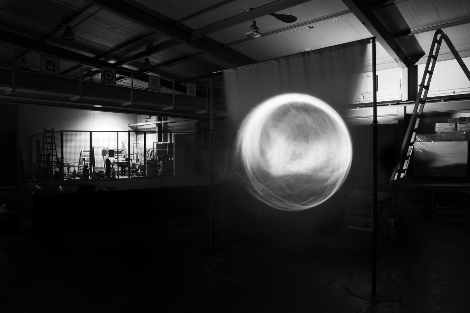
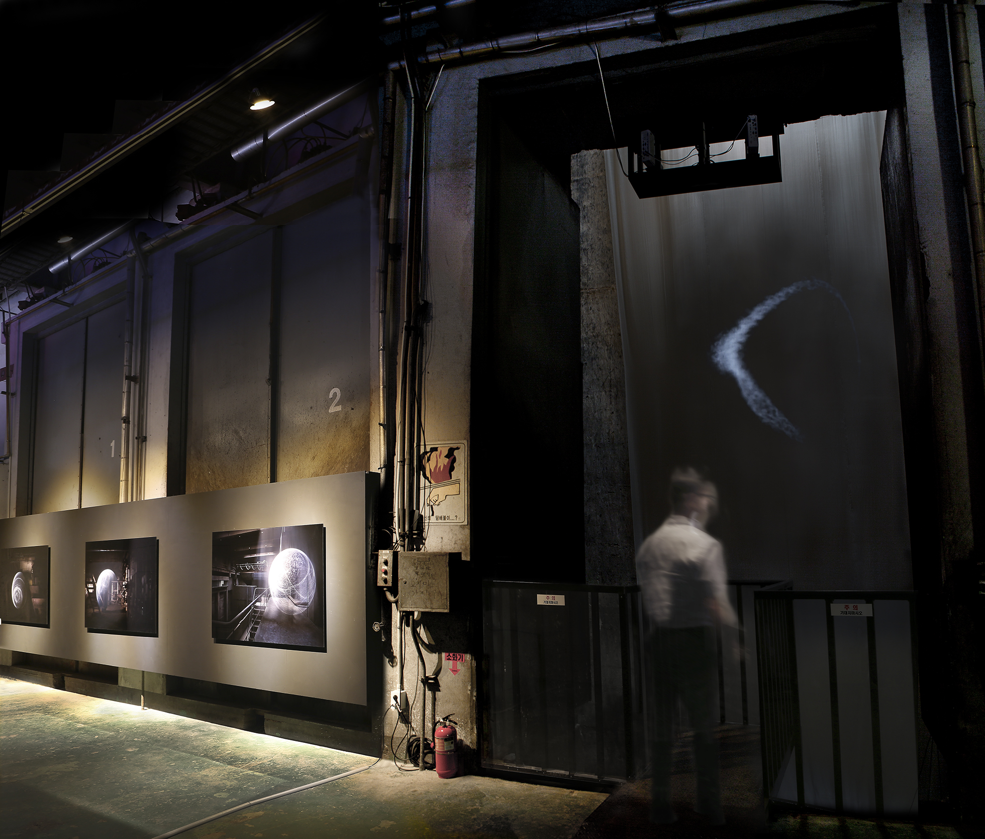
A vertical flag of fabric is stroked by the wind, displaced by curves of air, swinging back and forth. The fabric is tracked by a 3D camera whilst a projector replays a response onto it according to its evolving shape. As it sweeps, it leaves a trail of light which draws a heavy fragile moon floating in space. The flag renders this moon from another reality, the silk surface acting as an intermediating manifold between reality and virtuality.
This artwork is an installation set up within the concrete chambers of Bucheon city Incinerator, a stagnant industrial processing plant decommissioned in 2010.
At locations within the building, the artists collaborated with photographer Eunyoung Kim to capture moments of the moon being birthed. Long exposure photography trades the dimension of time for a dimension of space, extruding the moon into existence on a set of photographic prints, capturing a painting enacted by the details of the wind.
Inspired by the 2 moons of Haruki Murakami’s 1Q84 (a Japanese fictional book) and the flags of space travel, the artists present a portal into another existence where another moon orbits. This other place is made material by the fabric of the flag.
LIGHT BARRIER THIRD EDITION(2016)
Concave mirrors, Projection, Scanning, commissioned by the Asia Culture Center in Gwangju. The technology is enabled by Rulr, an open source graphical toolkit for calibrating spatial devices, created by Kimchi and Chips.
The installations present a semi-material mode of existence, materializing objects from light. Light Barrier Third Edition is a new installment in this series that exploits the confusion and non-conformities at the boundary between materials and non-materials, reality and illusion, and existence and absence.
The 6-minute sequence employs the motif of the circle to travel through themes of birth, death, and rebirth, helping shift the audience into the new mode of existence. The artists use the circle often in their works to evoke the fundamentals of materials and the external connection between life and death.
I think that Kimchi and Chips place a lot of effort into producing the Light Barrier and making it work, also as mentioned by Elliot Woods, when they started their project, they were not really earning a substantial amount of money and the project seemed really expensive to build as the concave mirrors and the structure needs to be customized built. This is also why the scale of the first edition of light barrier was much smaller. However as my own preferences, I like the first edition more due to the light beams were more focused as there were lesser mirrors used.
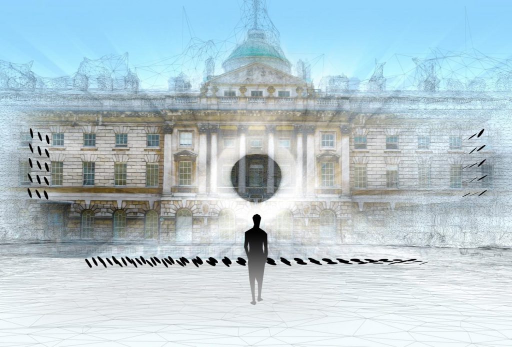
Halo (08 – 27 Jun 2018.)
Kimchi and Chipswill have a new outdoor installation, commissioned by Somerset House. Halo will be happening in London from 08 – 27 Jun 2018. 200 mirrors will reflect sunlight and together with mist of the fountains in the courtyard, a shape of light will be ‘drawn’ and suspended in the air. The mirrors are programmed to react to the direction of sunlight.
This kind of reminds of our Spectra light show at MBS, which make use of light projection and water sprays to create sort of holographic effects, except that it is done at night.
Kimchi and Chips really utilise technology by looking at the physics behind the machine. These states of semi-materiality created is as fascinating as any wonder of nature we could possibly encounter. And they make us immediately want to make sense and grasp the seemingly new material, only to discover it is just nothing but light.
I found the Thoughtful Interaction Design really enriching and there were many useful ideas which I could learn from. Although Lowgren was specifically mentioning about the topic revolving “Designing digital artifact”, like he mentioned:
“Interaction design refers to the process that is arranged within existing resource constrains to create, shape, and decide all use-oriented qualities (structural, functional, ethical, and aesthetic) of a digital artifact for one or for many clients.”
Thoughtful Interaction Design?
Good Design?
I did some research about Jonas Lowgren and his main area of expertise includes collaborative media, interactive visualization and the design theory of digital materials. He focuses on the digital world and “design” to him is very different from how I interpret it. He places huge emphasis on the “digital artifacts” while I am for the inclusion of more than just that. I think that his concept of thoughtful interaction design could definitely transverse from the idea of just within the digital world into the physical world because not only do we interact with the “digital artifacts”, we also interact with the “physical artifacts”, take for example, a normal physical door. By not placing a door handle on the top corner of a two meters tall door, it might seemed commonsensical, but that is “Thoughtful Interaction Design” to me.
I think that for an artifact(digital or physical) to be an amazingly-thoughtful-interaction-designed, it has to be design with the consideration of all targeted user, how and where will they use the artifact, and account for the safety while fulfilling the expectation of the users, the specification of the client, and when it goes above these basic of an artifact, it has to inspire other designers to follow or “copy” the system or the ideology behind it while simultaneously, the original designer/company would improve the existing design and strife for a better version because nothing is really perfect,
Working with design means that you continuously need to define and redefine what you think of as good design. It is a never-ending process of thoughtful reflections.
And when something was brilliantly designed, not only the customer wants it, the competitors(existing or potential) would want it too.
The iPod Generation 2
I think that the iPod classic 2nd generation from 2002 was brilliantly designed in the aspect of thoughtful interaction design, it had also changed people’s life drastically, even though it was not the pioneer of the iPod series, nor the one that made the biggest leap in sales, I personally think that the 2nd generation iPod classic was the breakthrough within the realm of interaction design, not forgetting that there were many iPod generations to come after the 2nd, each had their multiple system updates and then upgraded to the next generation and then came iPod touch, which gradually evolves to the latest iPhone X. (Just to be clear, I am definitely not a supporter of Apple and even dislike it as a brand, but their product marketing and system design sure is amazing.)
The biggest change that apple made from the generation 1 to generation 2 was the inclusion of Windows system for syncing the songs from iTunes, as the biggest downfall for generation 1 was that Apple forces the user to be running an Apple computer system to be able to use the iPod, this resulted in the potential user who doesn’t have an Apple computer to be excluded. In Generation 2, Apple included the Musicmatch Jukebox to manage the user’s music library and transfer music to the iPod which made generation 2 the first iPod for Windows.
I always think that the ipod were magical in a sense that the circular touch-sensitive wheel, these were really the thoughtful interaction design that was mentioned in Lowgren’s book:
Design work is given form and structure by designer’s own thought, consideration and actions.
These circular touch-sensitive wheel was designed in the consideration as of how they marketed the iPod: to”put 1,000 songs in your pocket.”(which was really ground breaking during that time). The designer took the system advantage(also the limitation) into consideration… Imagine that the iPod does not have the circular wheel for the user to scroll through the song list, and the user did have 1,000 songs, how long or how tedious would it take to click the down button or the next button to go to the 499th song in the list?
With the circular wheel, the user could easily scroll through the list at great speed by spinning the wheel.
The whole form and aesthetics, material used, hardware, software, even till packaging, was well thought of for the optimal user experience, the size is just right to be carried around in the pocket of jeans (target audience demographics placed into consideration), the placement of the screen and the directions was ergonomically constructed so that user could use it with single hand operation, back light of screen vs battery life were well balanced to have good visibility and above average battery life so that user could use the iPod wherever they go and it should last long enough until the user could charge it(understanding the target user). Every aspect of the iPod was efficiently designed to suit their target audience. And by watching the advertisement from that time, it is rather clear who the target audience was.
and then came this:
Young active hipster.
In Conclusion.
I think that through the eleven pages of reading, this quote impacted me the most as a designing student,
“We are all living in a world almost completely artificial and designed, and every new addition, every new design adding to this world has an impact on how we experience the whole”
(I like how it goes from a designer’s perspective to a user’s perspective here)
“Design is about shaping the world we live in by creating the conditions” and “it means that you influence people’s work, leisure, and everyday life.” It let me realize that we are actually living in a world that is partially ran by designer, every thing we saw, every thing we touched, was designed by someone at some point of time. We, the designers in making, may hold the power to change the everyday life of the people we’ve never seen in our life.
again, I had progressed much further since that post, mainly in designing the workable electrical and mechanical system that could fit into the Telephone and to write the Arduino code up.
First, lets start with the Final Video!
Back into the Process
Since the previous post which I’ve roughly did the belt system that drives the music card into the laser reader, I had added the motor to the system and tried it, at this point, it seemed to work as I thought all I need was to slow the motor down and it will be alright.
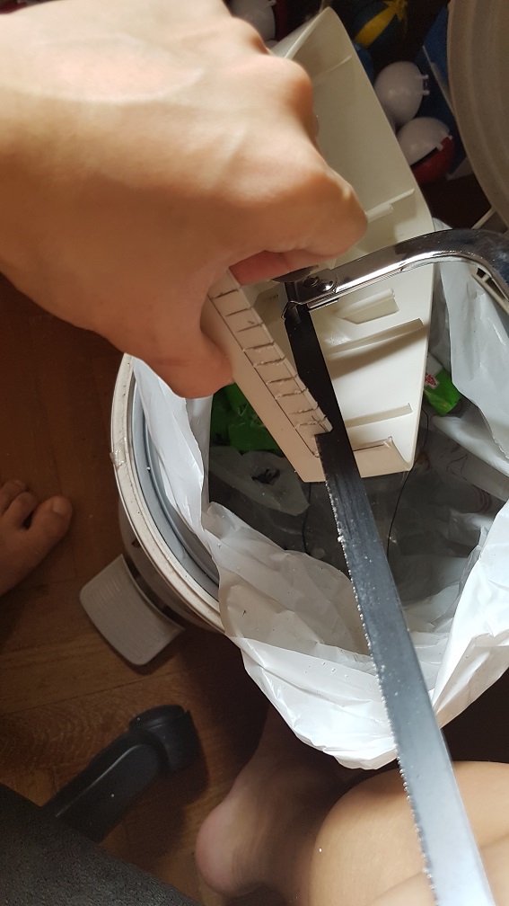
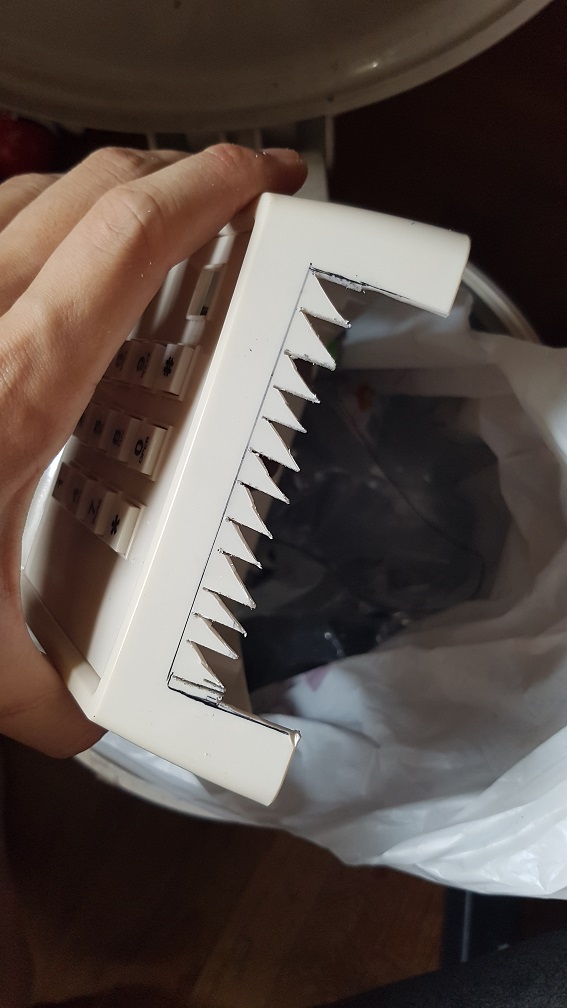
First I sawed the phone to remove the material for me to cut them easily later
and slowly, I cut them up
after chipping the plastic off, i constantly checked the dimension of it and trimmed a little at a time to prevent having a larger hole than I needed.
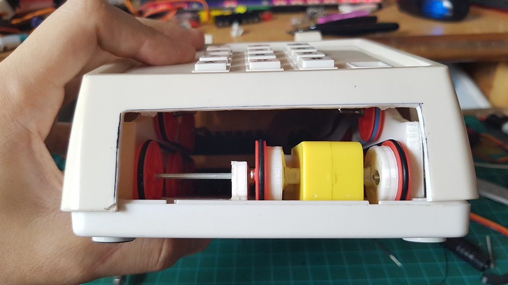
With this hole, I could finally see how it is looking internally and if there are any parts i made which was too tall in the case.
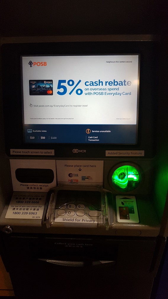
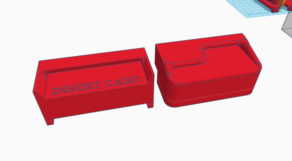
After I cut the hole, I proceed to modelling the card slot and i took inspiration from the ATM just to have the user to have something they’ve experienced and know how to put the Music Card in without instructing them, since subconsciously, I assumed that they interacted with a ATM at some point in their life.
This is the inspiration that I took from
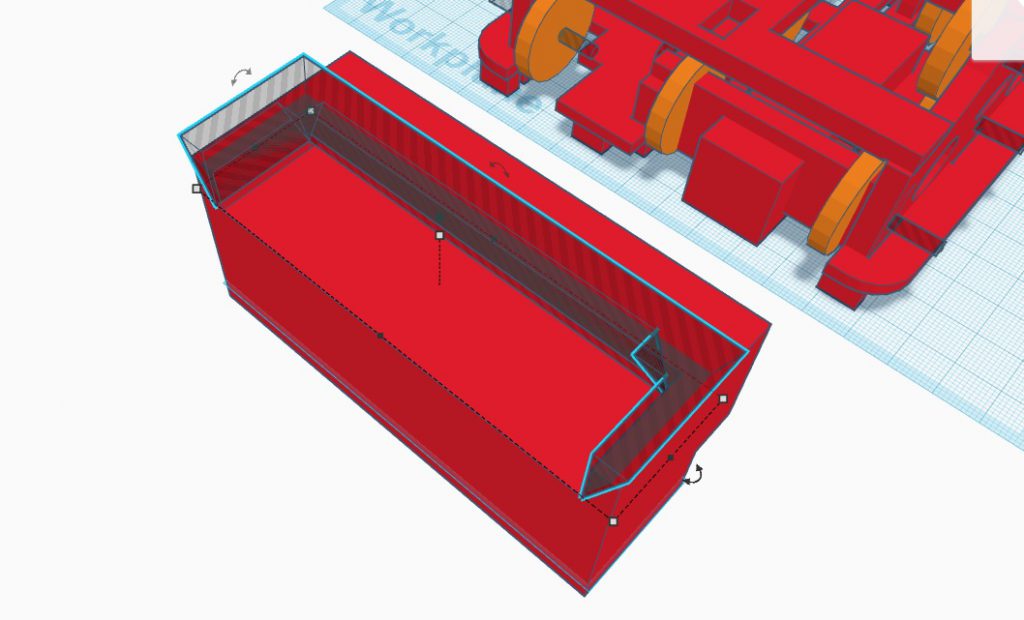
I used Tinkercad to modeled it and the cube like doesnt look like ATM card slot.
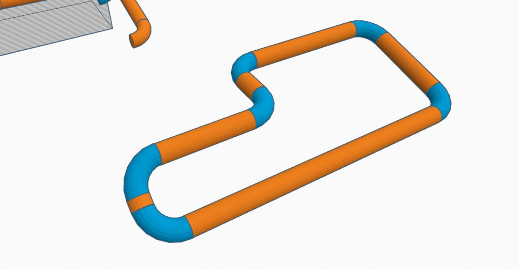
so i tried to use curve lines, and MANNNN Tinkercad was not meant to be used this way!! these angles and tilts of a pipe line was only done by brute force trail and error.
Version 1 on the left and Version 2 on the right.
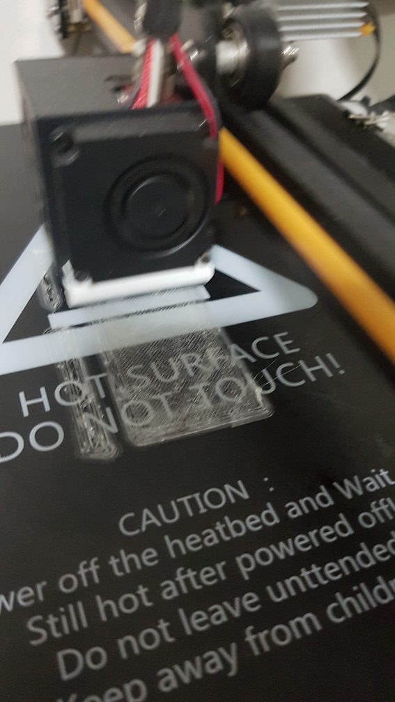
After the modelling which i am really happy with, I proceed to print it.
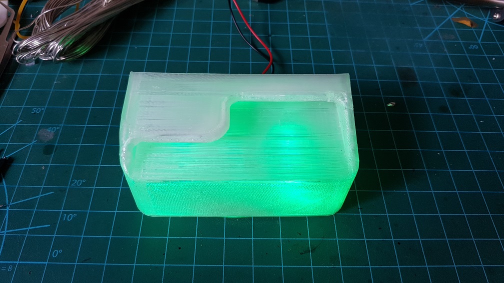
I changed filament to clear filament to print the card slot which was modeled according to the ATM
Half way printing, its looking really good
test of size with the music cards.
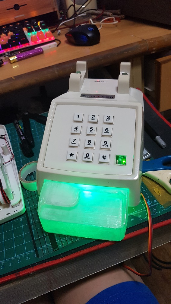
and i tested by plugging in one green LED in it and MANNNNNN IT LOOK SO MUCH NICER THAN I EXPECTED!! I WAS IMPRESSED.
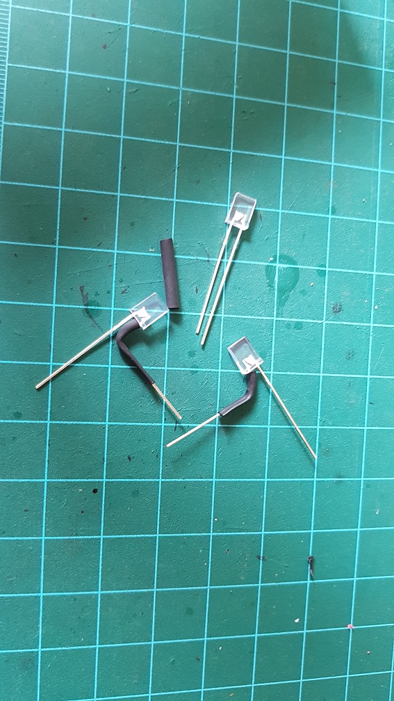
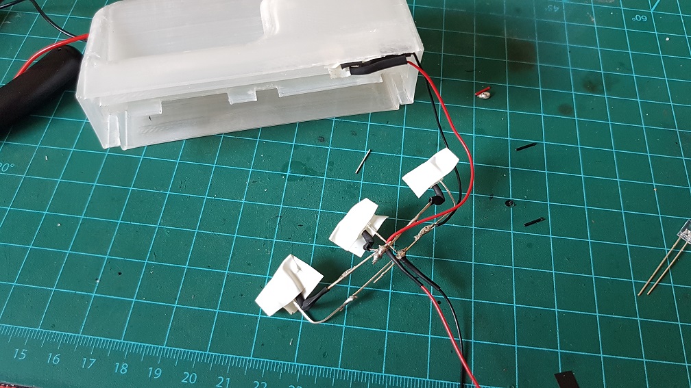
Since it was looking good, I went ahead and make a nicer LED system for it by soldering 4 LED(3 on the bottom and one for the top).
I used the flat and clear when Unlit Green LED so that i could stuck it in the shell on top.
and I soldered the 3 on the bottom and tested it out.
placing it in to see the effect again.
The light was too glaring so I sticked white electrical tape to diffuse the LED to make sure that they glow nicely.
and this is how the system would work.
How the phone should look
Next, I Epoxyed the speaker onto the bottom of the front belt drive since there is already a hole in the bottom shell for the speaker.
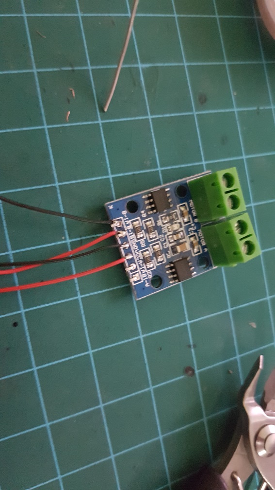
This is the DC motor driver which is used to run the 2 DC motor in the system.
and I soldered the pins too.
I thought I woundn’t need to solder this again… but… i happened to solder this for the 4th times..
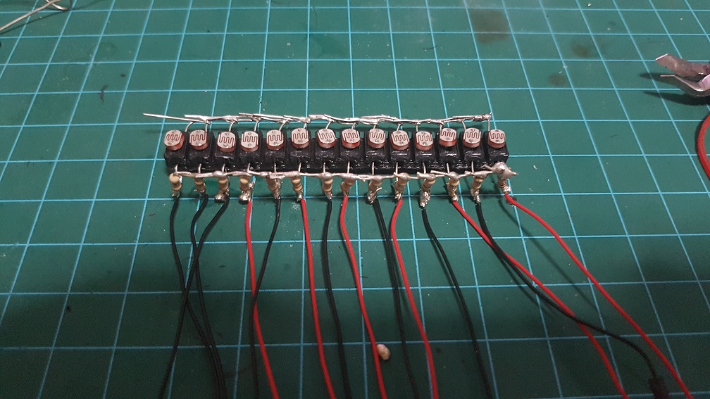
I extended the wires and used thinner and softer wires so aid me in the messy wiring withing the telephone afterwards.
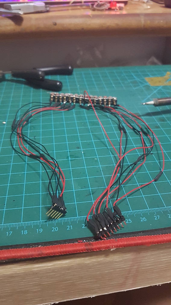
this is the wires for only the photoresistors.
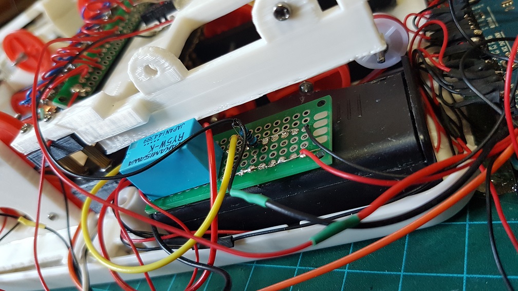
and I soldered the relays which control the 14 laser diodes and the 4 Green LED lights which runs on 2 AA battery to reduce the load on my arduino and to make sure the laser and LED have a stable current flow.
It was at this point then I realized that if i reduce the speed of my DC motor to the speed of the music, I wont have enough torque to pull the card in..
After an afternoon of panicking and finding alternative motor or even thinking to redesigning my whole belt system….
So to solve this problem, I tried to get the medium speed which is faster than what the song should be and will stuck about 30% of the time and removed the buttons (which detects card when user insert into it that trigger the motor to turn the belt.) that caused more friction. And I also jump start the motor by making it to spin at full speed for half a second to break the initial force required when the motor is starting.
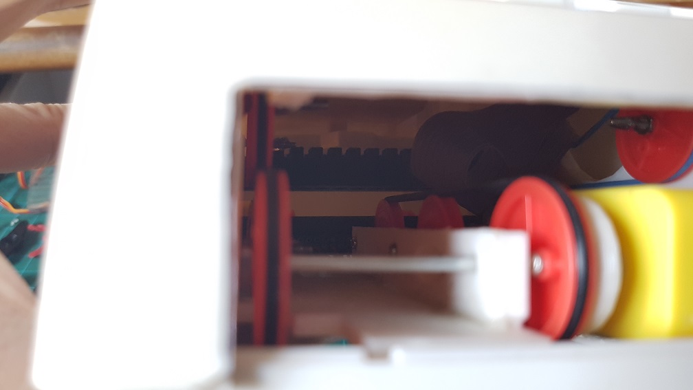
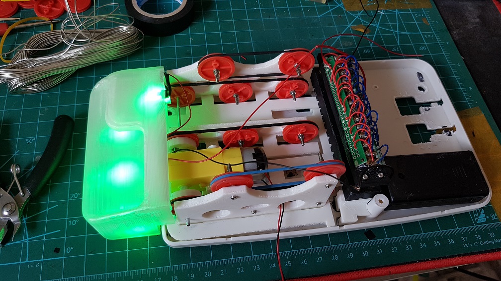
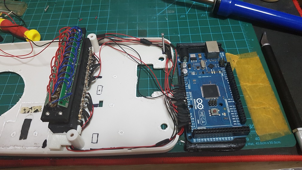
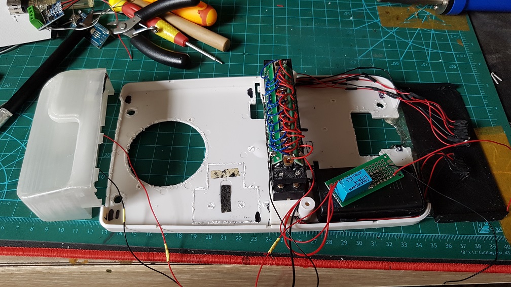
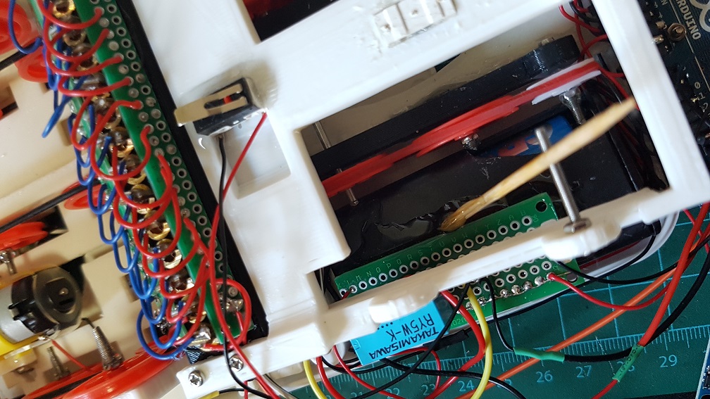
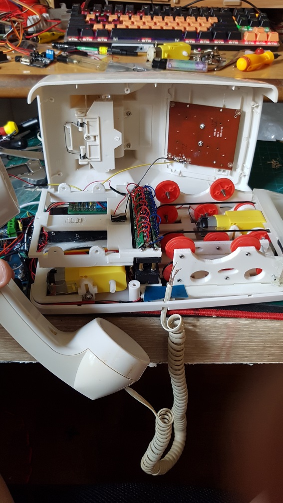
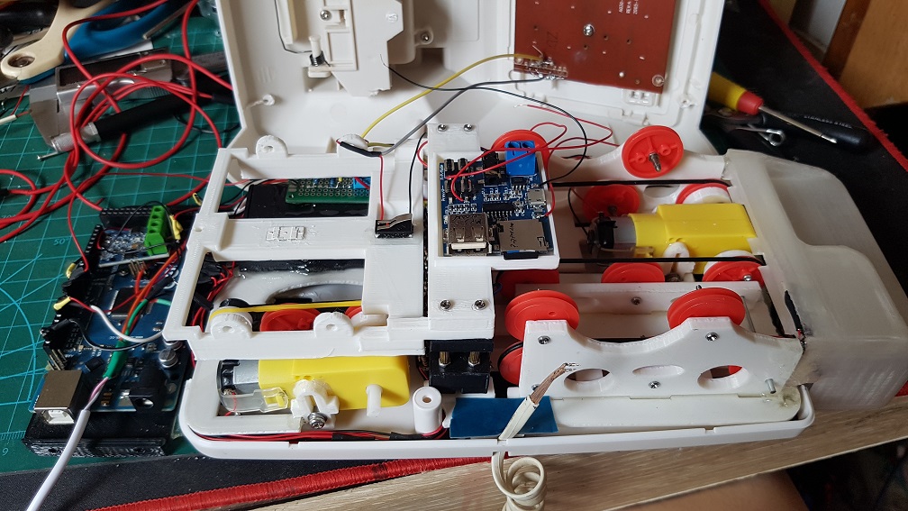
The messy configuration, components and wirings.
It took me some time to sort out these messy wiring and make sure that none of the wires interfere with the track that the Music card is going through.
The overall layout before the mp3decoder mount was printed and installed.
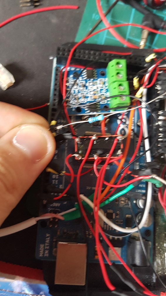
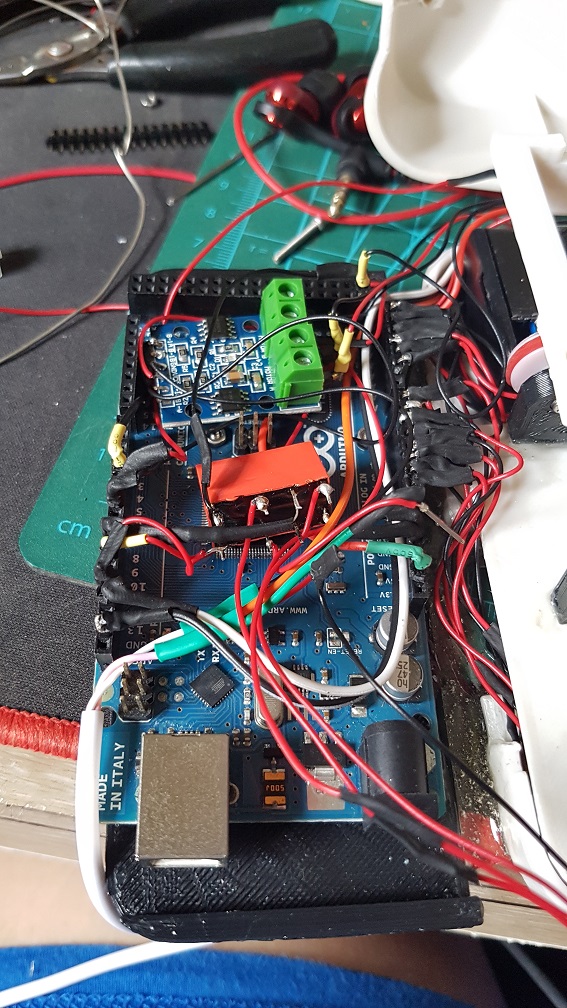
The relay which controls the LED and 14 laser diodes, it work as a ground for other buttons to do the pulldown resistor.
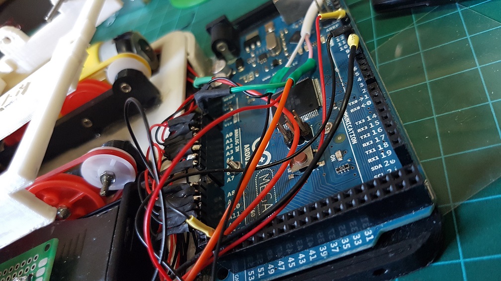
the only part in the whole system that was not soldered was the connection to the Arduino Mega as I intend to reuse it in the future.
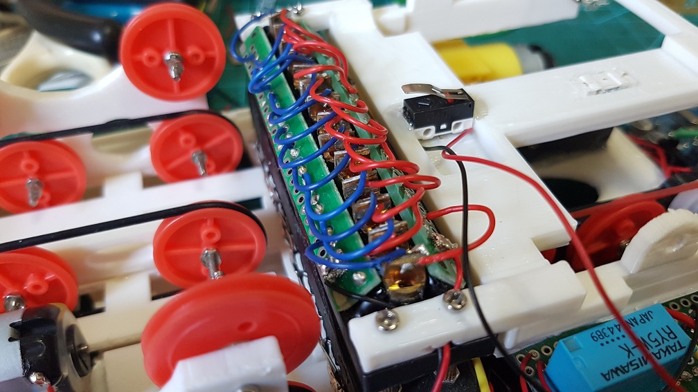
Closeup of the 14 Laser Diodes.
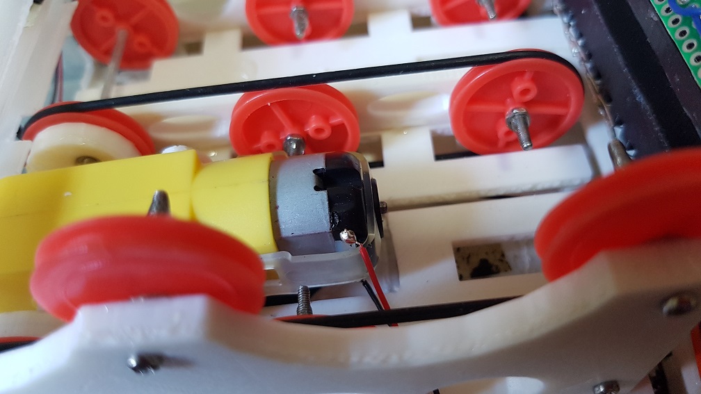
The soldered joint of the DC motor.
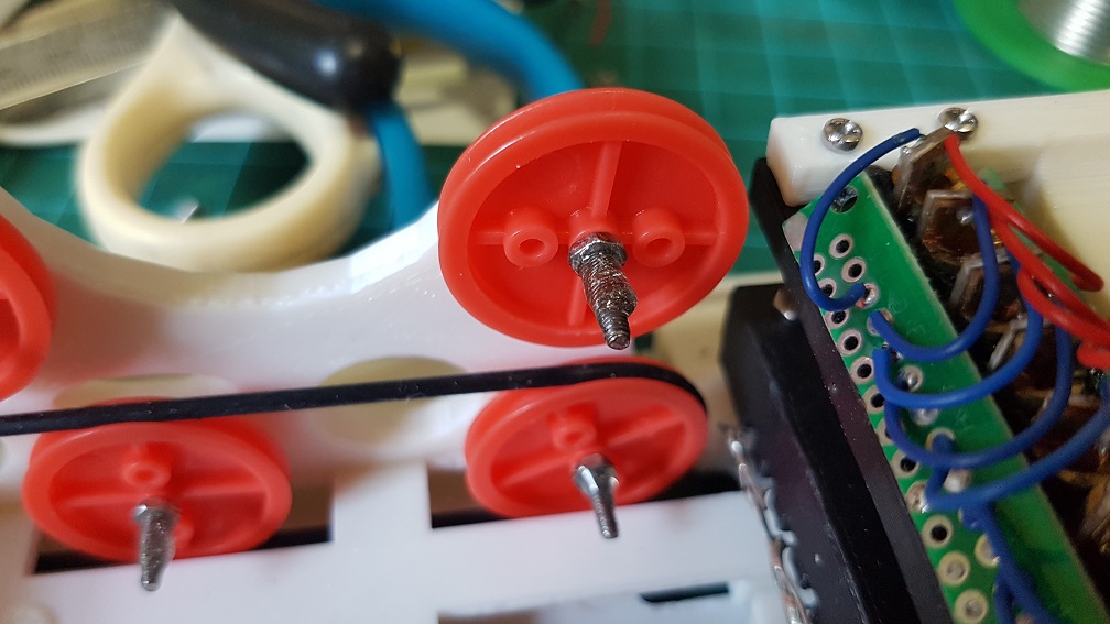
I’ve epoxyed the nuts of all the wheels for the belt drive to make sure they stay where they should be and don’t unscrew/tighten themselves.
I also Epoxyed the relay onto the case of the AA battery to make sure nothing is loose in the case.
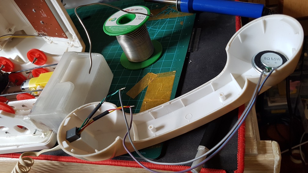
Soldered connection from the phone coil wire to the 8 Ohm 0.5 Watt speaker.
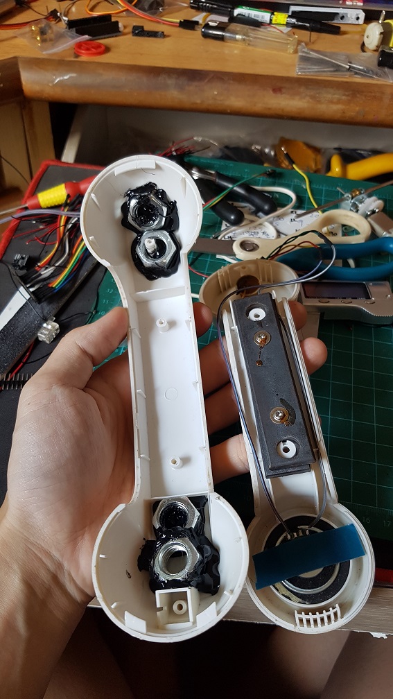
I also Hot-glued four big nuts in the phone to increase it’s weight to make sure that when the phone is in the place, it is heavy enough to press the button down.
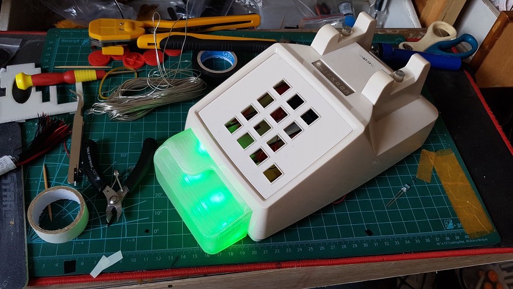
the assembled phone
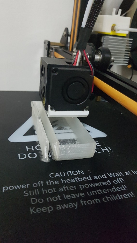
after the MP3decoder mount was modeled and printed, it looks quite good overall!
I used this 400 Ohm resistor to reduce the volume of the tune when playing the music card.
And added a relay that cut the power of the MP3 Decoder since I am not able to control it digitally, the only way was to let it play until it is the start of the next track and cut off the power to stop the voice track. it also switches the circuit of the phone from the MP3 Decoder to the Arduino pin at the same time.
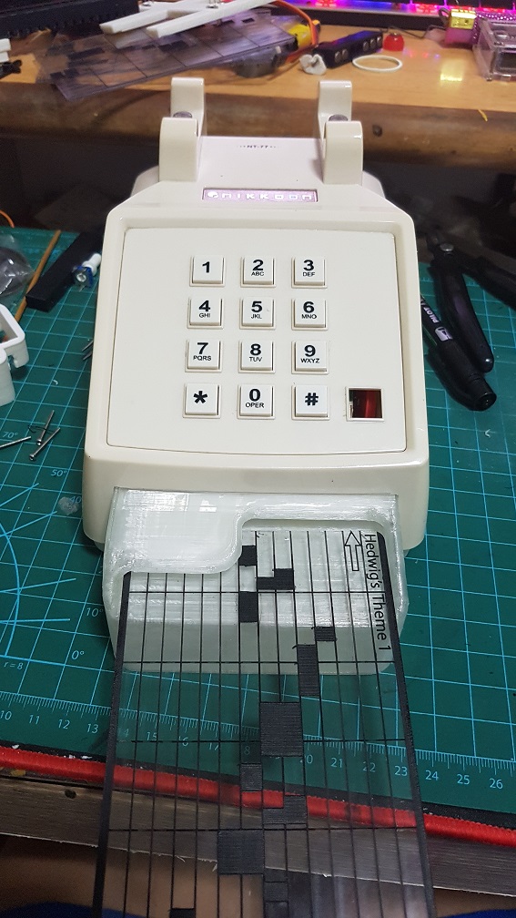
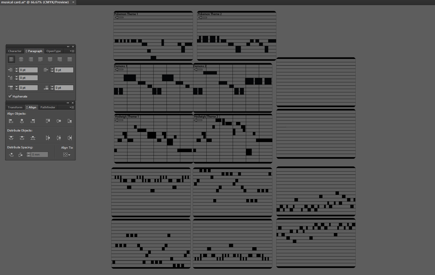
Some may wonder how did I make the Music Card..
I copied a few from online like Demons by Imagine Dragons, Harrypotter’s Hedwig Theme, and Pokemon Theme song, These were labeled on the card and those that weren’t labeled was What I composed myself. Since I have no music background, I did it by trial and error to give it a tune.
This was screen recorded when I tried to compose my 4th tune for this project:
after this was completed, I screen shot it and import into Illustrator to trace it into the Card layout which I made.
AND how about the voice command in 7 different accent?
well, this is relatively simple, just type whatever I want on Webbased Text to speech reader and have it read it out in different accent and edit them in premiere pro to cut them up to the exact same length(9 seconds) and put them into the SD card within the Obseleting Instrument’s MP3 Decoder.
Why did I made it to speak different accent? It was to engage the user and make them feel like there was really life in the system where they called/receive call from a real person, like if they discussed with their friend and their friend said that there was a Indian accent while what they heard was the British accent, they might want to try Obseleting Instrument for a few more time. The accent there is there to add variables in the system.
In Conclusion
Throughout this Project, I’ve learnt many things like how to model objects in Tinkercad and make measurements properly, there are always failures in everything that I modeled before it works, and this is why 3D printing is a good prototype process where I printed it out and tested it to know if it work or not, if it doesnt, I will shave off some piece to see if it fits, if it does, I will make new measurements for the edited model.
Also, to have a Telephone case in the start and scale everything into the Telephone case was really a challenge especially at the start when I could not measure how big the internal was and could only make a guess and print some test print to try it out.
In this project, I realized that if I were to do a project that require multiple fields of knowledge like mechanical and electrical, It was better if I did not know how hard it will be, if I were to know that every part of the project will be something that I don’t know, I will be too afraid to jump into this project. I did something, realized that it doesn’t work and find solution to that single problem and proceed to work on the project and faced another problem, solving and learning one problem at a time lead me to the completion of the project.
Now that I had completed the project and looking back. Obseleting Instrument is really a complicated project as a whole, but thinking about it, I am just putting many small system into one project- like using one laser diode and a photo resistor as a switch, playing a tune when triggered, a physical button to sense if the phone was picked up, using a relay to control circuits of different voltage, running two DC motor at the same time and so on… Obseleting Instrument is just a collection of small systems, which I personally thinks was what made my journey of doing this project really interesting because I explored the basics of these components and learnt a whole lot through it.
Continue from my part 4 of this project updates, This is the final part which leads to the completion and is rather long as many things from getting the power supply, modelling, testing, painting, assembling to coding had been done in the past 2 weeks.
First, the final video of The Curious & Timid Turtle.
And then, into the process….
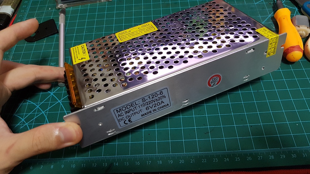
NEW POWER SUPPLY!!!
At the end of last post, I was waiting for the power supply to reach and it did during these 2 weeks so I’ve tested it out, The one that I bought is a AC-DC converter at 6V 20A when all I needed was 6V 8A, i decided to buy the higher Amp one just if i need more amp in the future, and I could also share the supply to my Interactive device project during the End of sem show.I did some wiring afterwards.
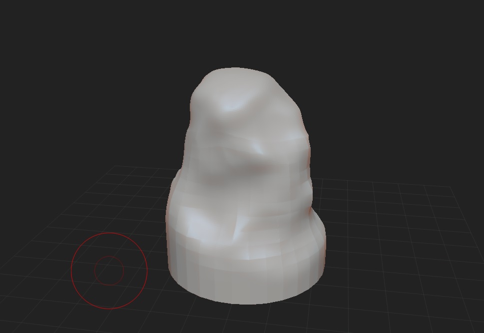
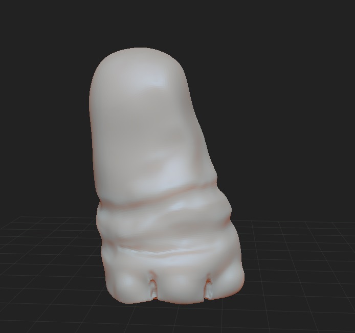
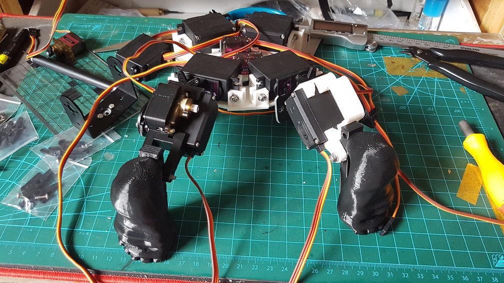
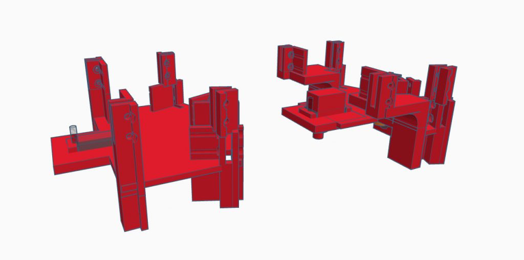
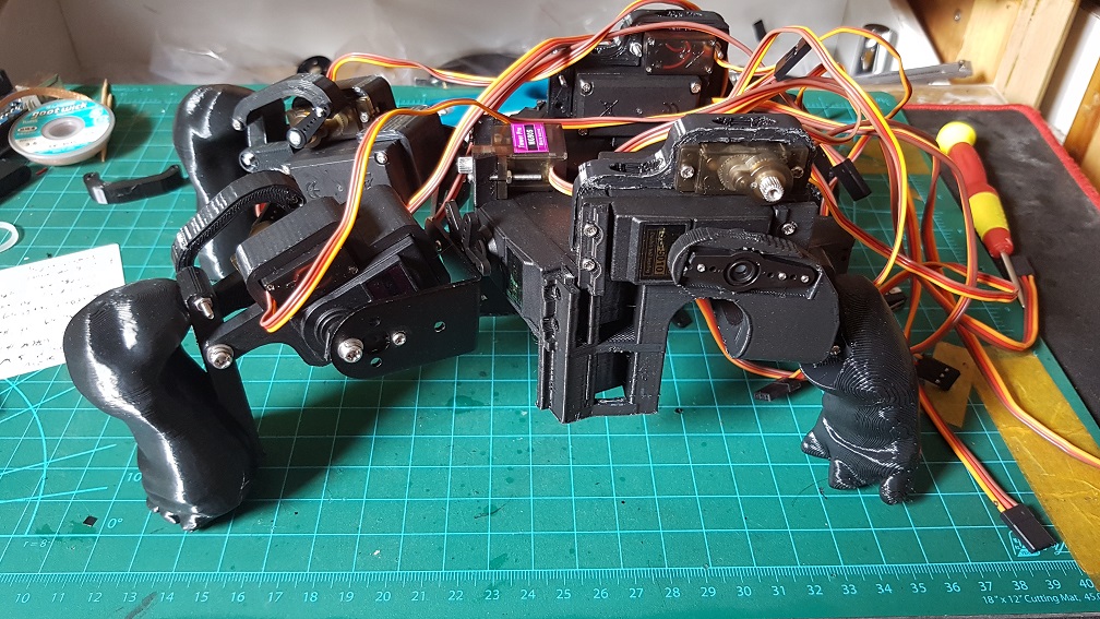
Since the last post that I’ve decided to change the system in the legs to save space and shorten the overall length by stacking a smaller MG90S on the MG966R to act as a lever system to pull control the legs. After testing this system out and seemed to be working, I merged it with the turtle leg that I’ve modeled in Zbrush, I don’t know about Zbrush before this project and it tool a long time just to model the shell, the legs and the feet.
Backleg model
Backleg model before final
Frontleg model
Frontleg model before final.
I merged the leg with the previous test “rod-like” leg because I’ve already gotten the dimension in there so i just need to scale the Zbrush modeled leg accordingly to fit the “rod-like” leg.
changing of the entire base layout to reduce size and increase EFFICIENCY for the back legs.
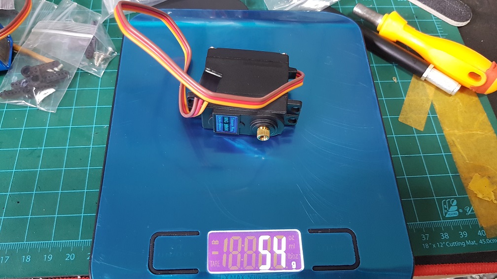
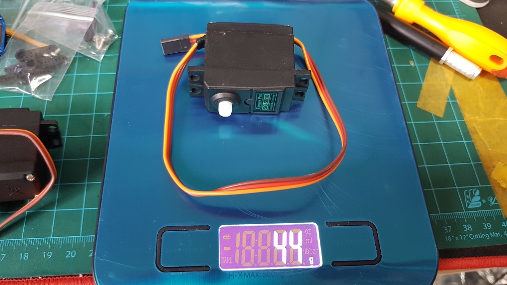
At this point, I was wondering if I should change the MG966R(metal gears) into SG-5010(plastic gears) due to weight issue I might face later after adding the shell and so on, so I weigh the motors and decided that I should change the back leg to SG5010(but I changed it back to MG966R one day before submission due to the internal gears got loose in SG5010)
MG966R is 54g
SG5010 is 44g, the difference is 10g so by switching 2 motor, I could save 20g of weight in my system. and so I did.
Major changes were made for whole layout of the base due to various reasons – the backleg will move differently from the front and since my project is basically a turtle with round shell instead of a flat one, it made more sense to use a smaller but higher layout rather than a flatter and wider one to make use of all the space within the shell.
This was the previous layout(Version 4) which made the whole shell really flat and big
and this is Version 5(left) and Version 6(right) which I stacked the servo for the back leg on the shoulder servo of the front leg.
Since my Zbrush was cracked, it crash rather often and I did the same thing over and over if I forgot to save frequently and hence it took quite long to model anything, but well~~
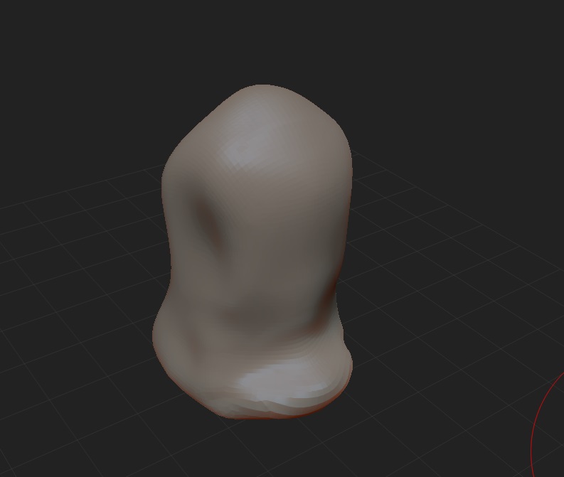
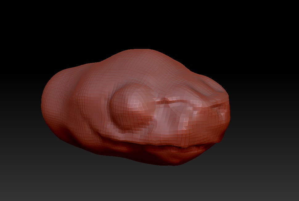
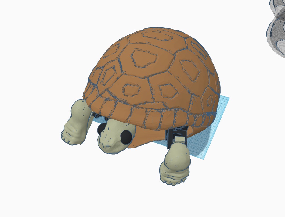
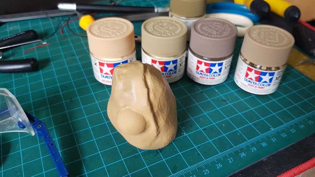
The head started off as a sphere
and tried to model it as close as the turtle head as possible.
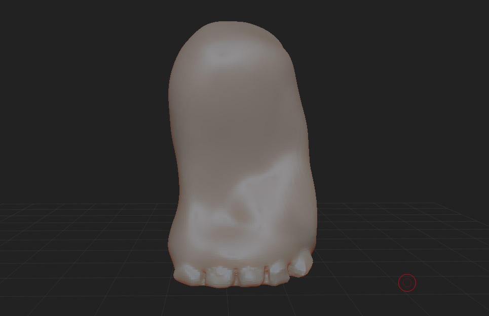
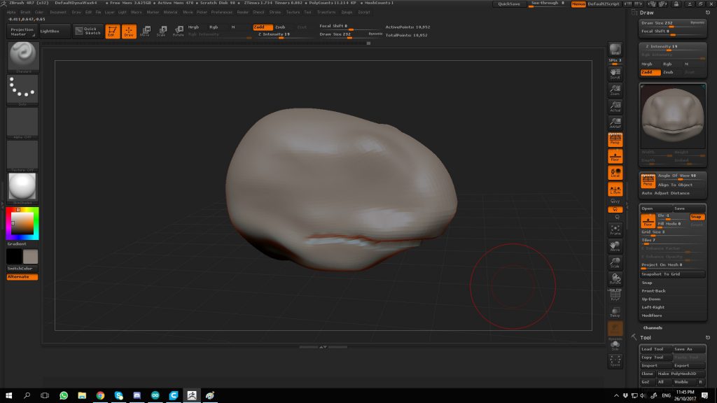
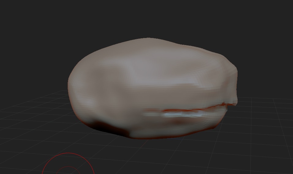
and some general shape edit
slowly, I edited it to look like a reptilian head, and instead of getting the real look of the eye, I’ve decided to enlarge the eye to give my turtle a cute look (and because the eyelid looks too hard to model).,
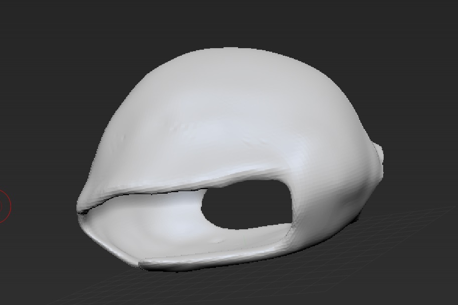
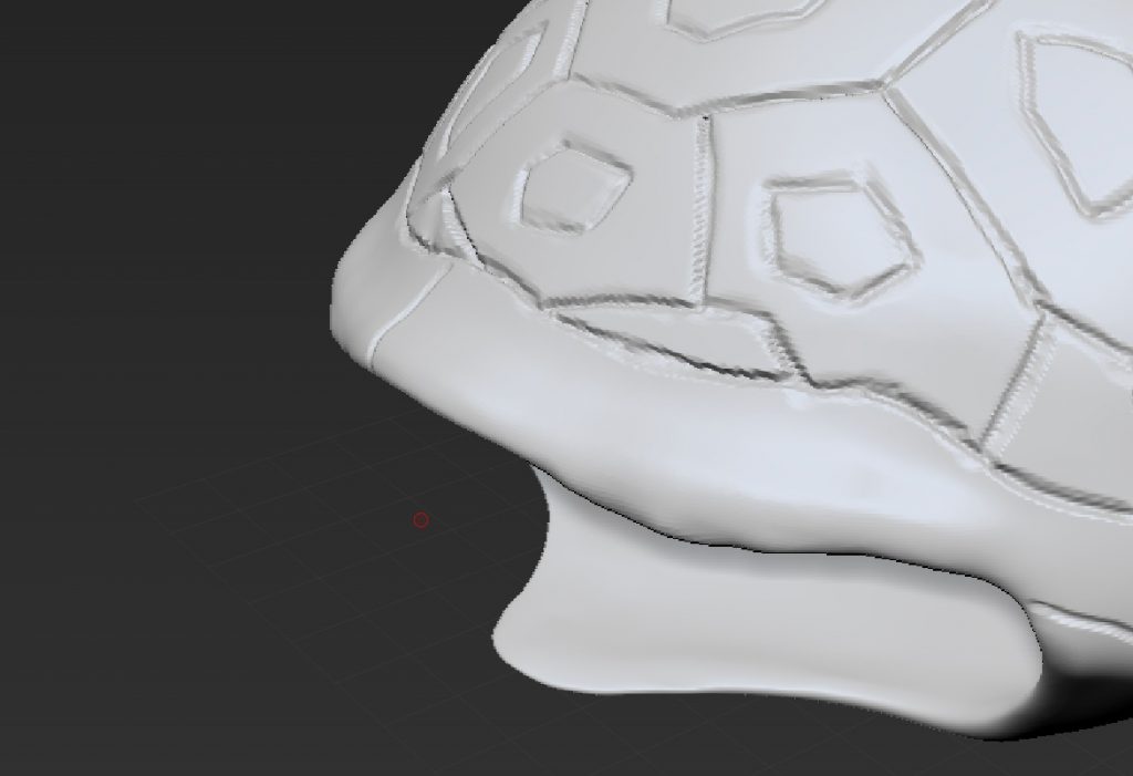
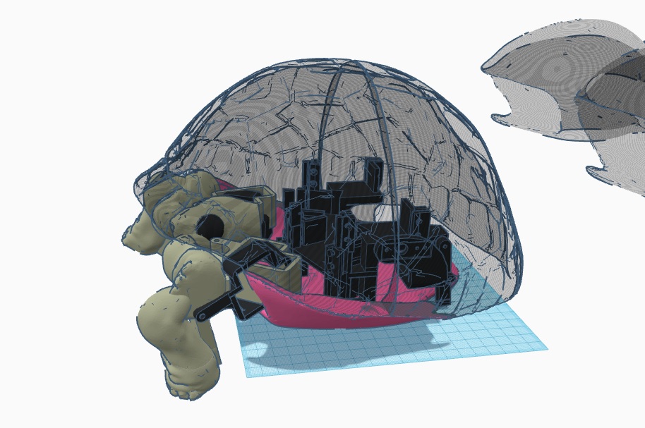
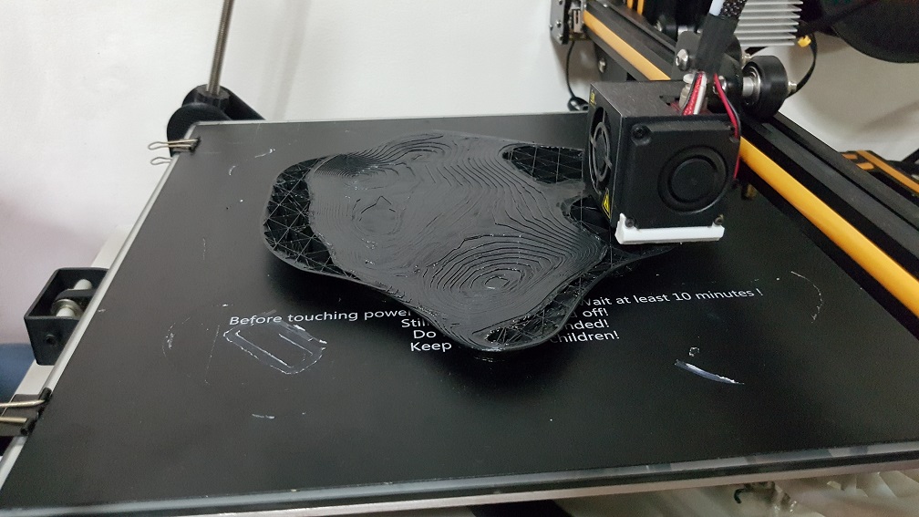
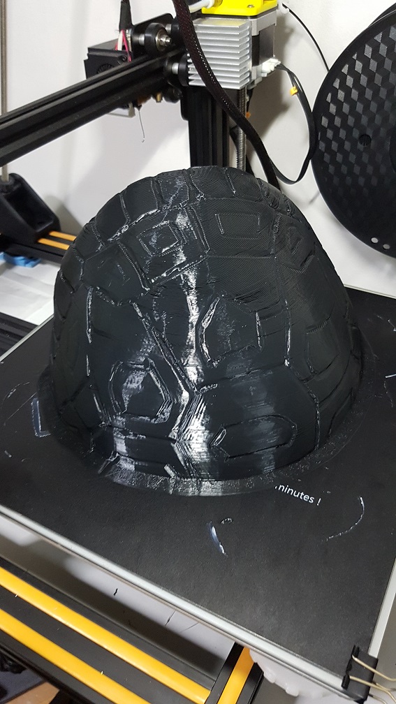
As for the shell… it took so much time and crashes to get it right, because the shell cannot be too thin(unable to print later) and cant be too thick (too heavy) and I cant find a function that could allow me to see the thickness (like reduce opacity of the material to see through), so everytime to check the thickness, I have to export into STL, and import into Tinkercad to check the thickness.
This is like the version 11 of the shell.
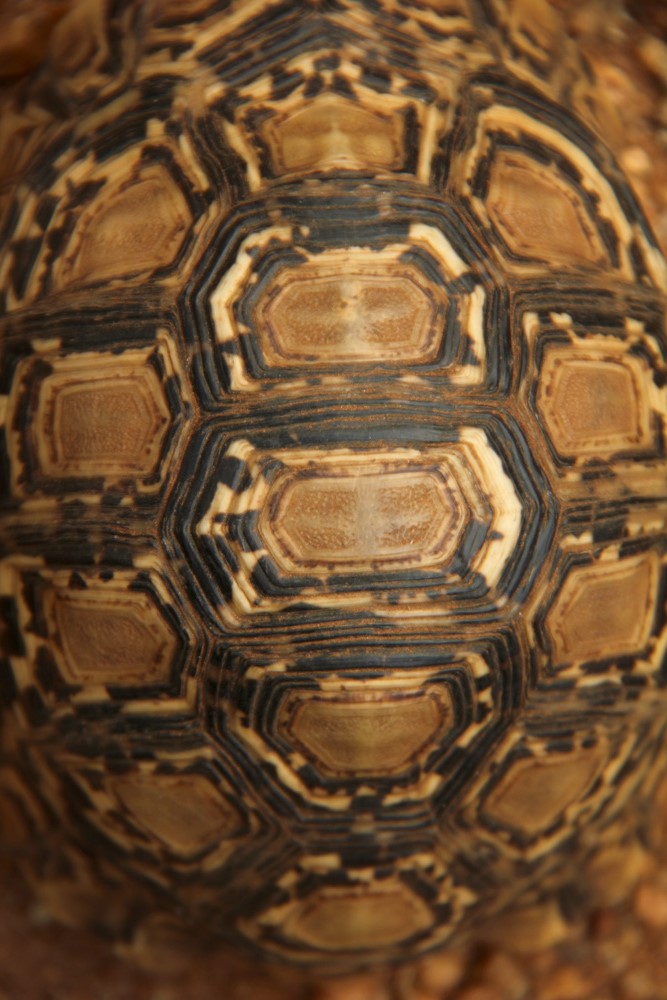
I used this image as the sample for my shell pattern
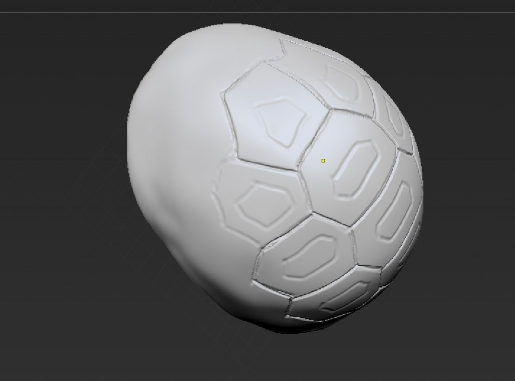
topview when I marked the turtle pattern onto the shell
and i further carve the pattern out.
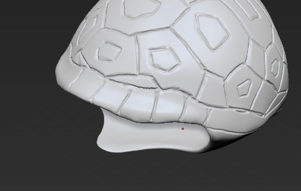
the rim of the shell i did without any reference and I marked it out
and carved into it.
Everytime I made major changes to the shell, I’ll have to import to Tinkercad to check the thickness and shape.
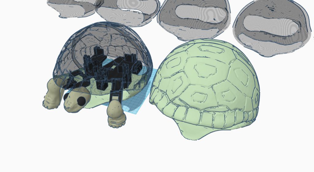
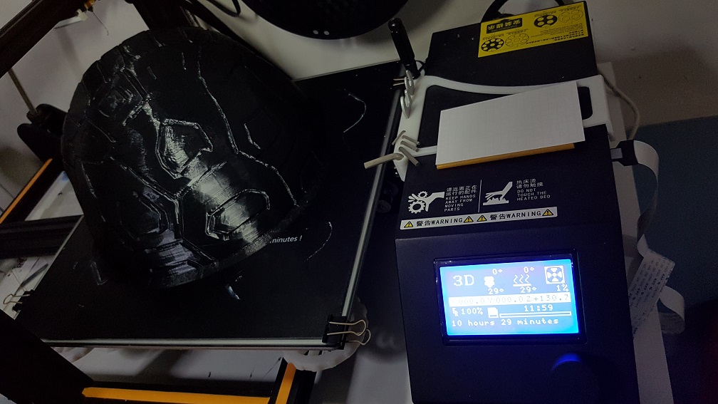
this was almost the final shell before splitting the shell for printing.
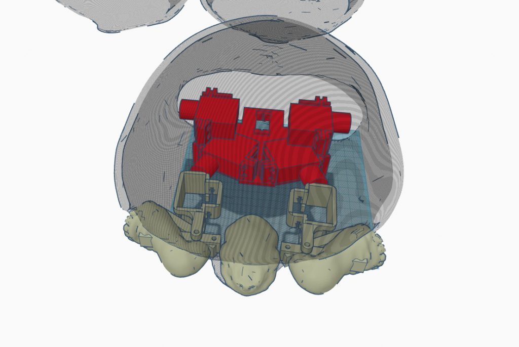
I split the shell top(transparent) and bottom(Pink) in Zbrush because its following the shape of the pattern of the shell, and the top half into 2 in Tinkercad as a straight cut will ease my printing later. I also added 4 holes that allow me to reassemble them using bolt and nuts later.
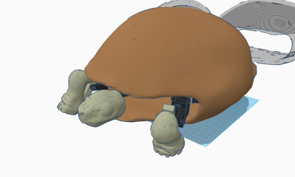
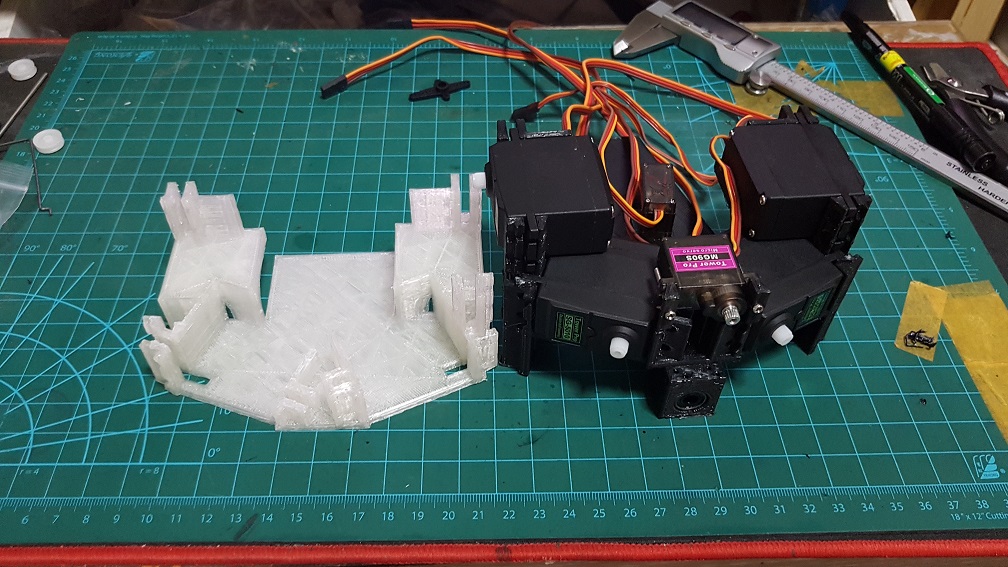
The comparison of V4 base with V6 base. V6 is much shorter at 150% higher,
The white one was Version5 which was a test print that I realized that the motor is unable to be fitted into it so I cut some material off and remeasured.
the front of the base is a liner bearing that i could slide the rod for the head.
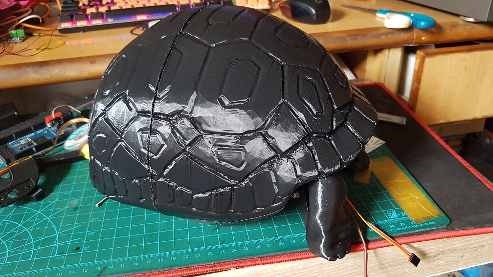
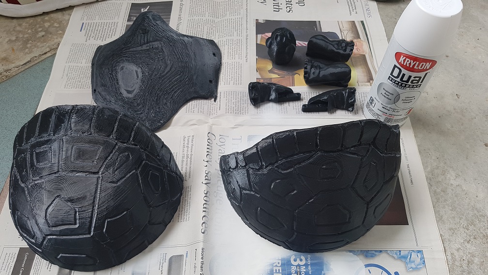
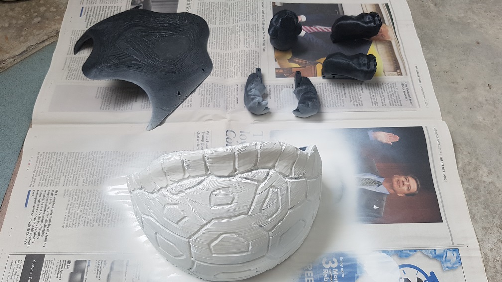
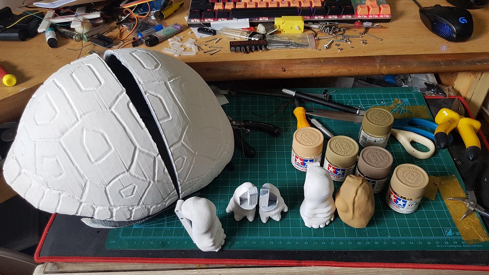
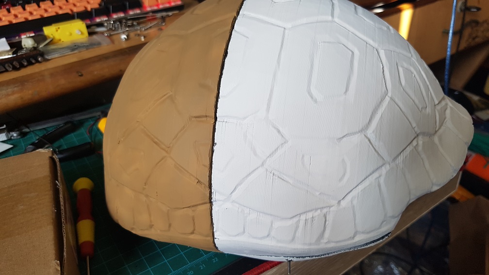
I sprayed the overall colour of the turtle with Tamiya Acrylic paint.
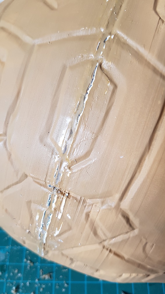
halfway through the spraying, I remembered that I need to epoxy the two pieces of the shell together first.
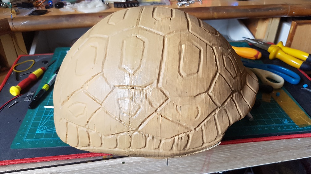
and so I epoxy it 3 times and sand off the extra epoxy to hide the glue line by a bit.
although it is still visible, I think it is a reasonable standard since I will be painting it further with darker color afterwards which will hide the glue line more.
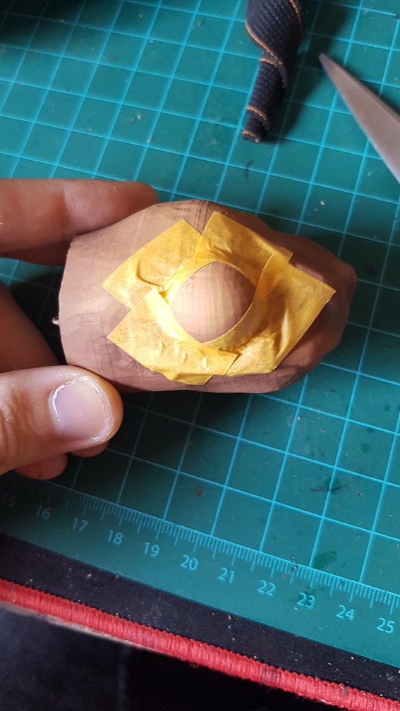
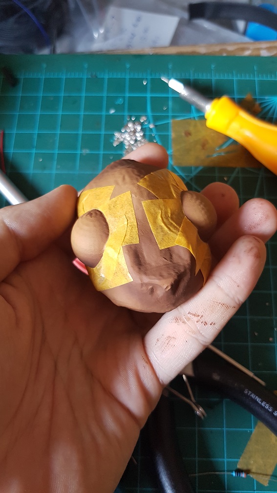
and i masked the eye using tape for me to spray it black and glossy
and i carefully cut out the tape in the shape of the eye.
After this, I added a few lines of code to substitute the button pressed with sound sensor to make the turtle more intractable and a few more actions that made it more timid looking (head peeking out to check the environment before the whole body come out.)
In conclusion:
Overall, I really liked this project although I kind of regretted trying to make a turtle during the process because the shell is giving a lot of layout and movability problem made me kept thinking that if I were to make something without shell, it will be so much easier, but the reason that I first wanted to make a turtle is the best is because the shell naturally hide all components that break the user’s perception that this is a robot and a turtle is my spiritual animal, now that I finished the project, I am really glad that I sticked to my initial idea of making a turtle and persevere through all the problems I faced(mainly hardware and mechanical problems which I changed my system and design so many times.).
With more time, I am sure that I could code the turtle be able to be scare back into the shell by another sudden loud noise – I tried to change the delay in my code to Millis multiple times and it do every action in the sequence twice so I sticked to using delay for now, which disabled me to write the activation code for using the sound as a trigger since it is in a delay loop. But, it looked really nice for now even if there is only one sequence of movement and I am glad that people were thinking that the turtle is cute when they saw it.


 To experiment with speed and delay of Lattepanda with unity to control arduino, which is not bad!
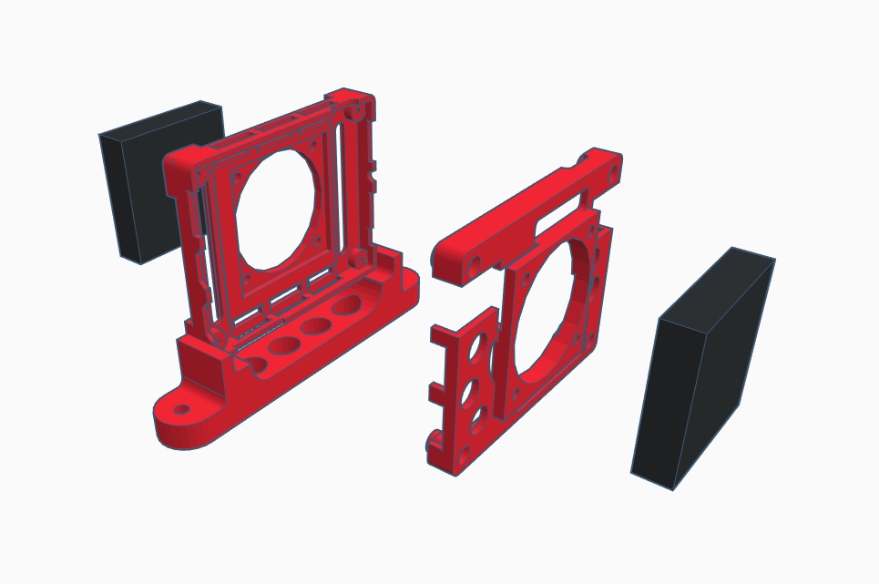


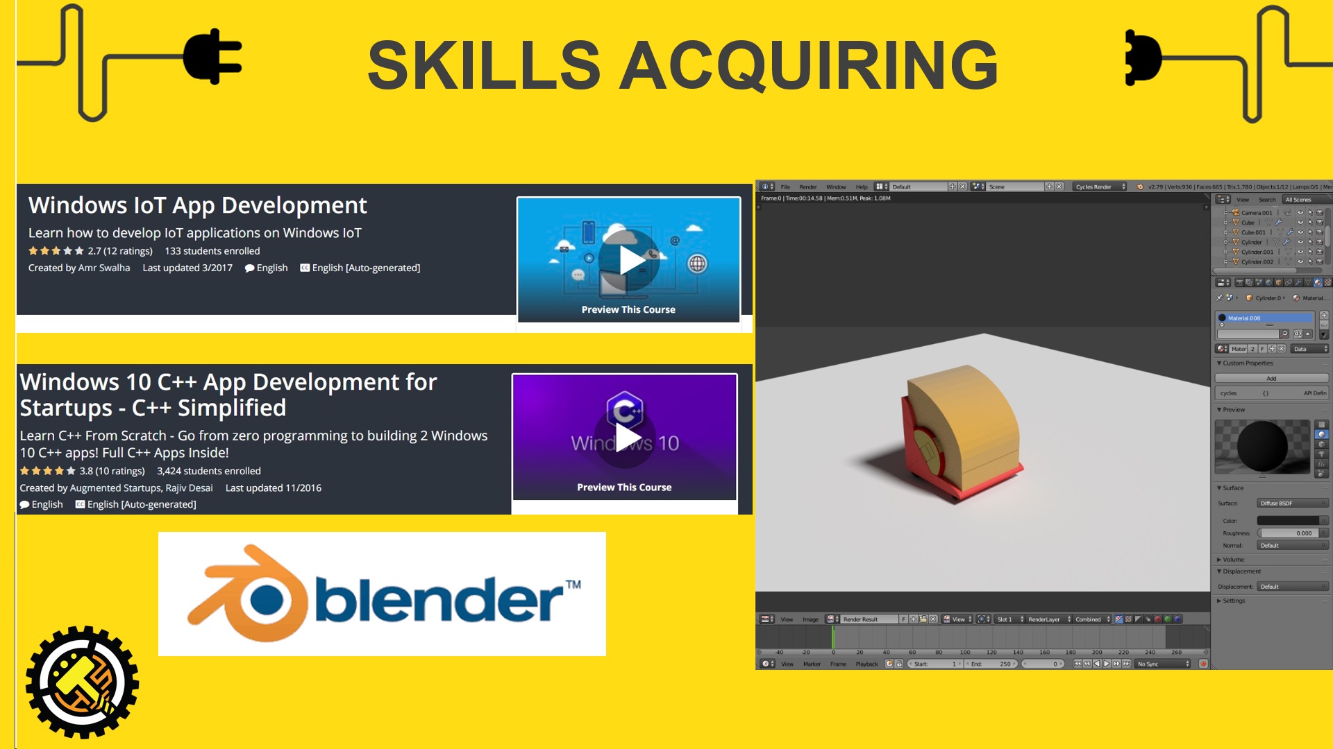


 https://www.udemy.com/the-complete-windows-10-c-course-and-build-2-apps/
 https://www.udemy.com/windows-iot/
 https://www.udemy.com/the-complete-design-course/
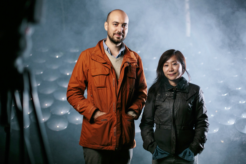


 This is a 8 Ohm 0.5watt speaker that will be plugged directly into the Arduino.
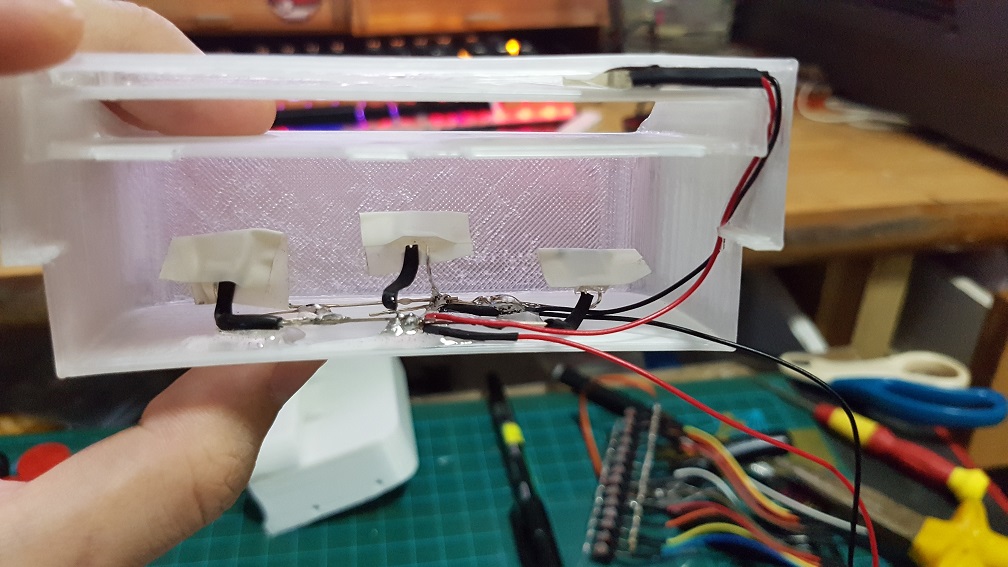 I also Epoxyed the 4 LED into the card slot to prevent them from sliding around.
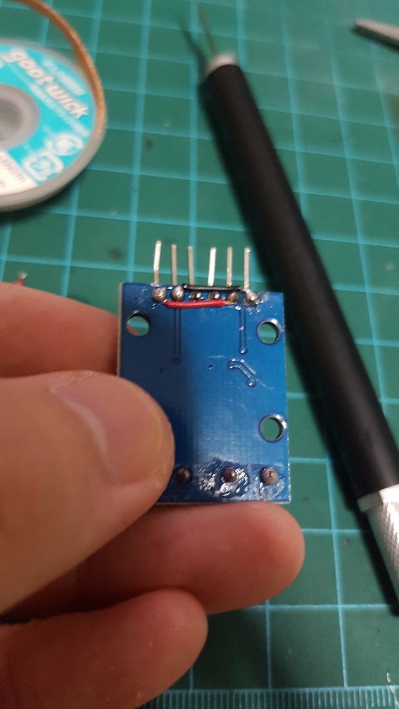
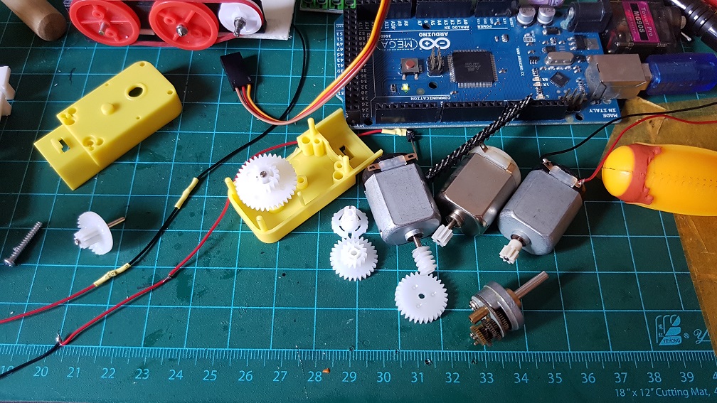
 And then I found that I have a longer DC motor with metal gears built into it and i tried to figure our if I can incorporate this gear box into my current system, which is also rather impossible as the ratio for this gear box is about 1:45. when I only need about 1:5 to 1:8. if i use this, I will have the belt driver running too slow.
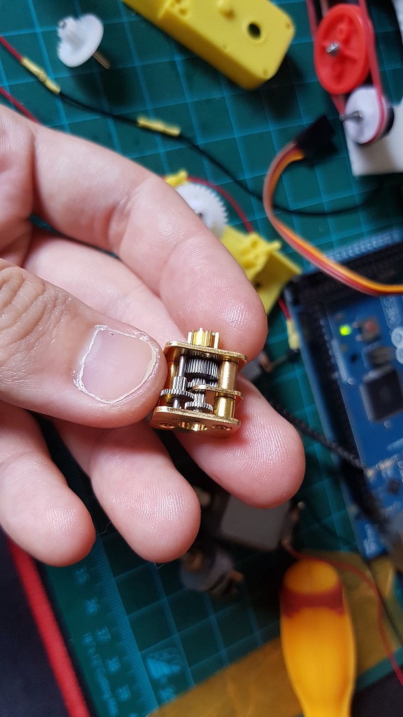 same goes for this, but this is 1:250… even slower.
 after trying out the workable speed of sound and getting stuck by removing the buttons.
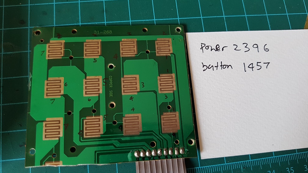 to make use of the original button on the phone, I’ve figured that the 12 buttons runs on 2 different circuit which I could simply solder these number together and make all the 12 buttons into one button, so nomatter which buttons the user pressed, it will be registered as one button pressed.
 Because I cut off the Redial button on the phone to make space for my belt driver system, I epoxyed the Redial button back to the case as there are no PCB supporting it.
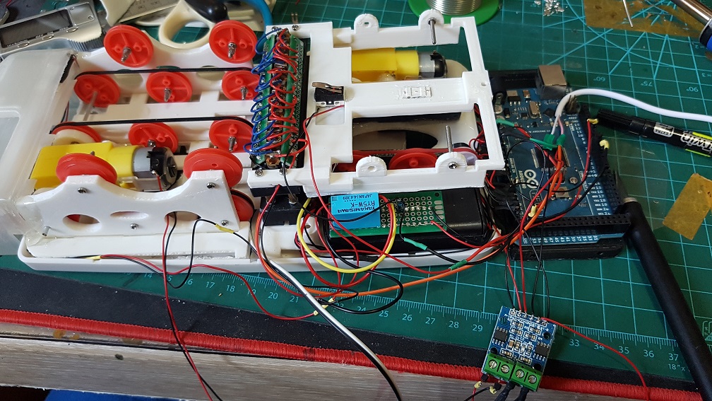
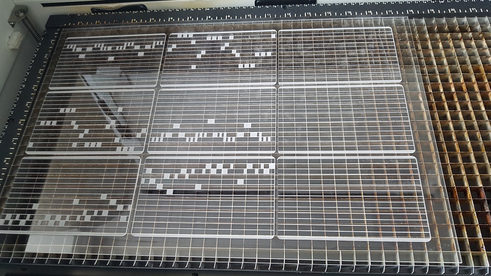 Laser raster and cut in school on 2mm acrylic.
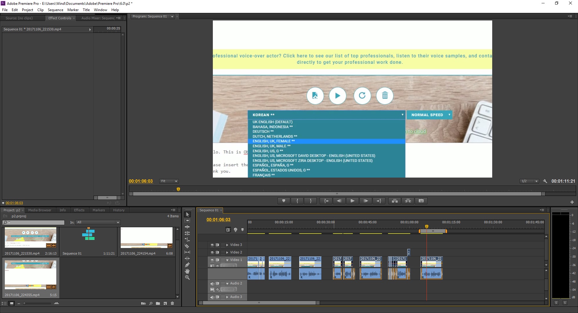 I really like the Japanese and Korean accent, its really funny!
 I am really glad that this many piece worked well together and this was the biggest challenge.. since there are so many components working together (electrical and mechanical), even if one of the parts failed, it would not work as well as it is now. So I considered myself really lucky that the parts happened to work well even when there are misalignment everywhere.
 I did some wiring afterwards.
 And after the wiring, I did power test, it could easily run 8 servos simultaneously with nothing overheating. which is a great news for me!
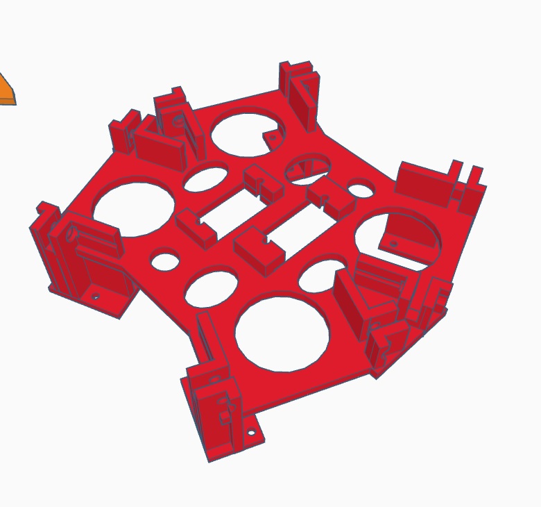
 This was quite the final base before I added the mount for the small backleg servo and the servo driver mount which will be attached it using screws.
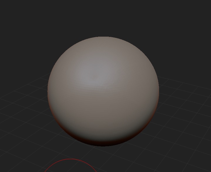

 Nothing is more satisfying in removing the support in one whole chunk(I did alot of cutting before this video so I can pluck out in one piece.)
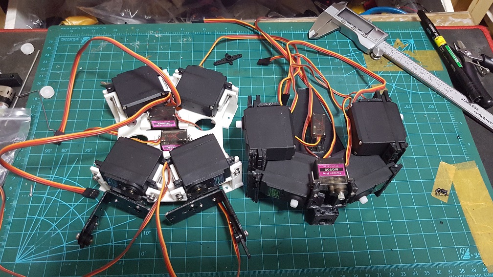

 this is the liner slider an an aluminium rod for the head system.
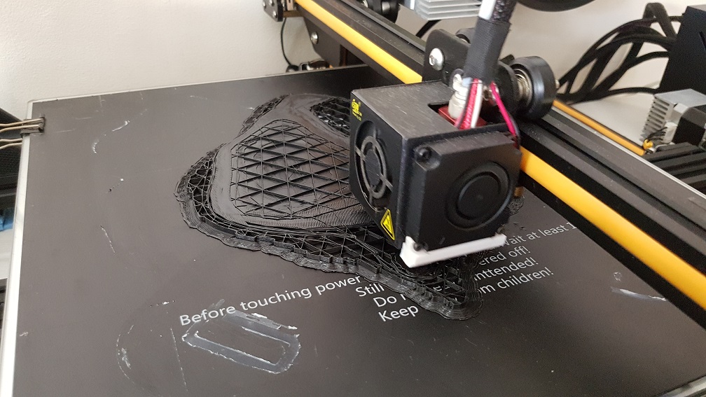

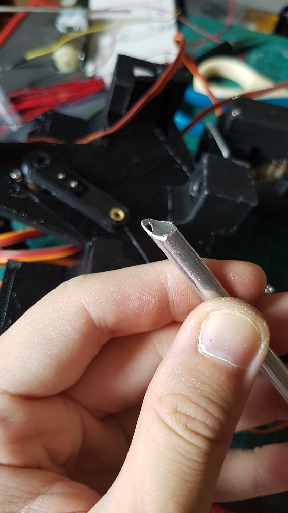
 testing out of the head slider and to mark the length I need it to move and cut.
 The mechanism to slide the head that I will use after cutting the rod to almost the size I need.
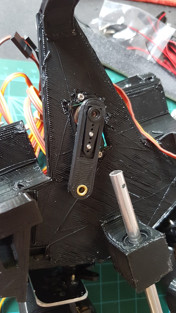
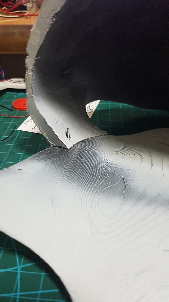
 this is the final mechanism for the head after I printed a small piece to prevent the wire from tilting too much when pushing the rod.
 the head could be push and pull out nicely even before adding the string to control the tilt of the head.
 metal rod were epoxyed into the head to tie the elastic thread to control the tile of the head.
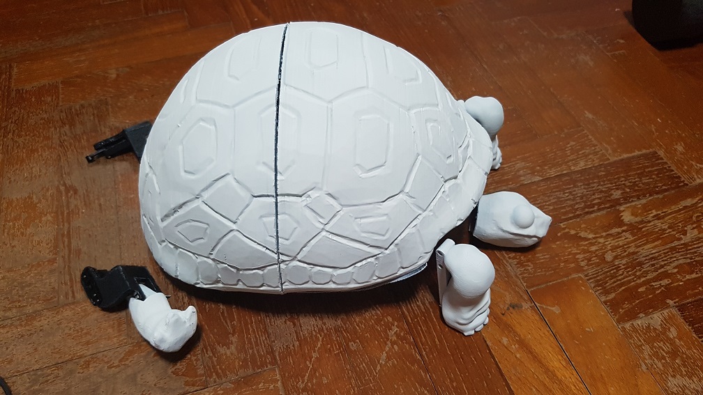
 The final test of the turtle before I finally started coding it. The head uses elastic thread because it will go forward and retract, since I dont want anything to be loose and might interfere with the shoulder servo motor, I decided to use elastic thread so that the thread wont be loose when the head is retracted.
 This is the almost completed sequence of action,the turtle’s movement is quite restricted due to the shell and the back leg is unable to push the turtle forward because of the shell’s restriction as well as the weaker servo(MG90S) which is responsible for the forward and backward thrust, while the MG966R is strong enough to lift the turtle up, so the turtle could do movements up and down but not walk.
 This was what made into my final turtle with many component being edited into the next version.