FYP Process 5: going against the Law? Hardware+Software

According to Isaac Asimov ,

the three laws of Robotics:
1) A robot may not injure a human being or, through inaction, allow a human being to come to harm.
2) A robot must obey orders given to it by human beings except where such orders would conflict with the First Law.
3) A robot must protect its own existence as long as such protection does not conflict with the First or Second Law.

Sounds really awesome isnt it, of course, there are situations that the robot will be forced to break these law, but again…. what if a robot is made to go against the first 2 law?

1) A robot may lightly injure a human when required to get the task done.
2) A robot may not obey all orders given to it by human beings.
3) A robot must protect its own existence and continue to execute the first and second law.

sounds really funny to me, doomsday robot? AHAHHAHA! sure, why not? ok maybe not. These laws are still in conceptualizing phase and if it made into the final project, it will be quite funny for those who read or knows the three law of robotics.

What was done until now after the last update?
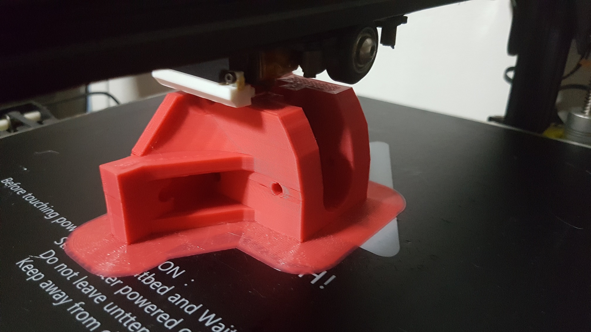
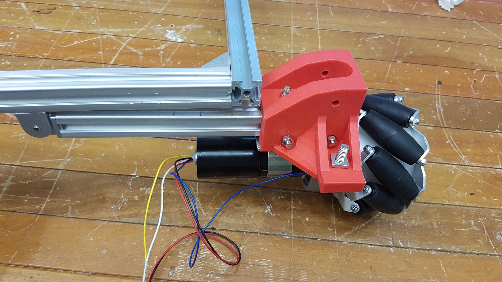
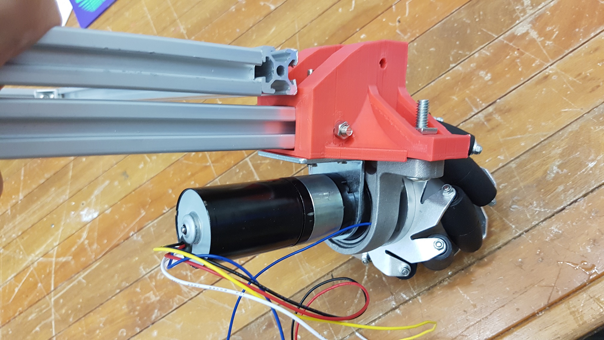
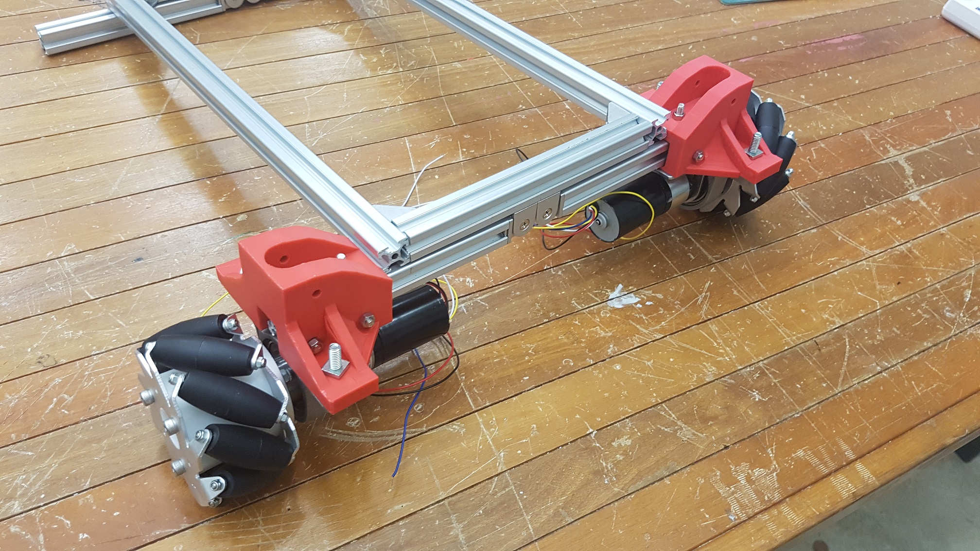
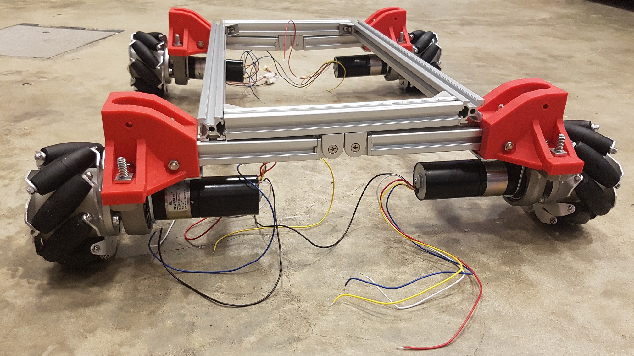
re-structure robot:

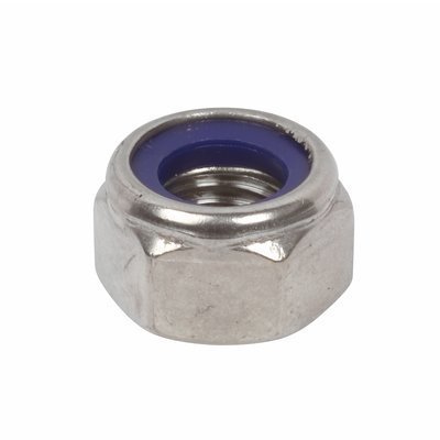
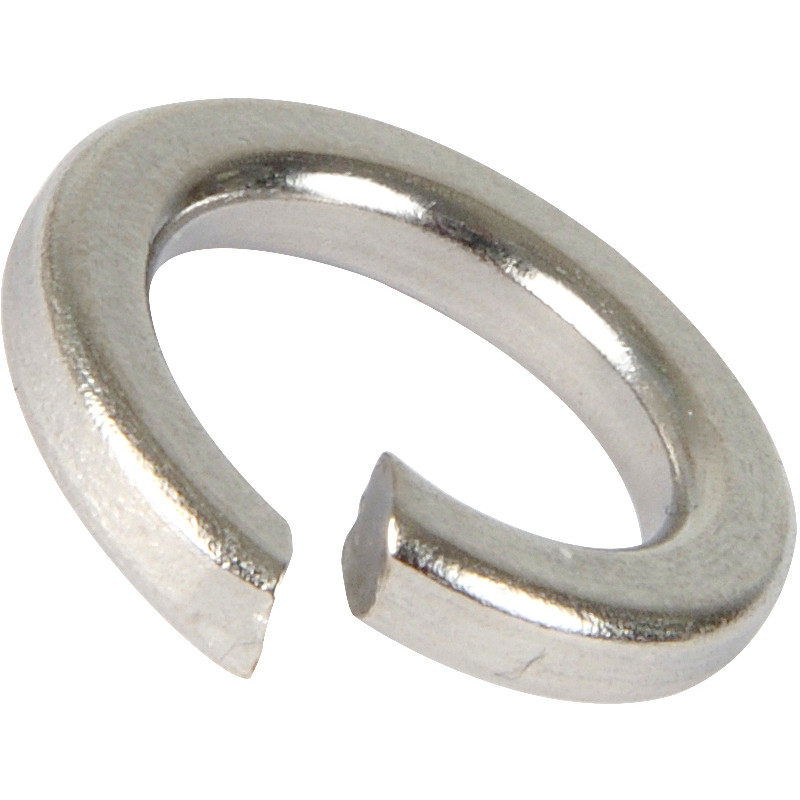
As of the previous update(the one before the presentation) whereby I’ve construct the wheel and the base structure for the robot, I’ve noticed that the parts get looser and looser even when I tighten all nut and bolt in every connections, that was because of the vibration when i move the structure around. To counter this problem, I’ve dissemble the structure and change all bolt and nuts to self-tighten nuts (Nyloc nut) paired with a spring washer to reduce the rate of it getting loose overtime. As a loose part will get looser overtime through vibration, if this was not done at the early phase(now), it will be a real hassle at the end as I want the robot to have a relative fast parts replacement (so no joints should be joined with permanent solution like super glue) and this solution of the combination of spring washer and Nyloc nut is the most effective solution for its cost(time and money).

Nyloc Nut, to “lock ” the nut prevent slippage of the nut:
Image result for Nyloc nut

Spring washer, to prevent loosening through vibration

Related image

LED matrix animation:

The LED Matrix used is 4 x 1088 8 by 8 LED matrix which will be used as the animation for the eye of the robot, it will be attached to an arduino Nano which will be labeled as “Emotion Processing Unit” in this project to give it a more developed feeling to bring it away from the “Arduino = prototype” perception.

Parola Library code: Robot eye library code:animation made through a program that convert animation to LED matrix codes:

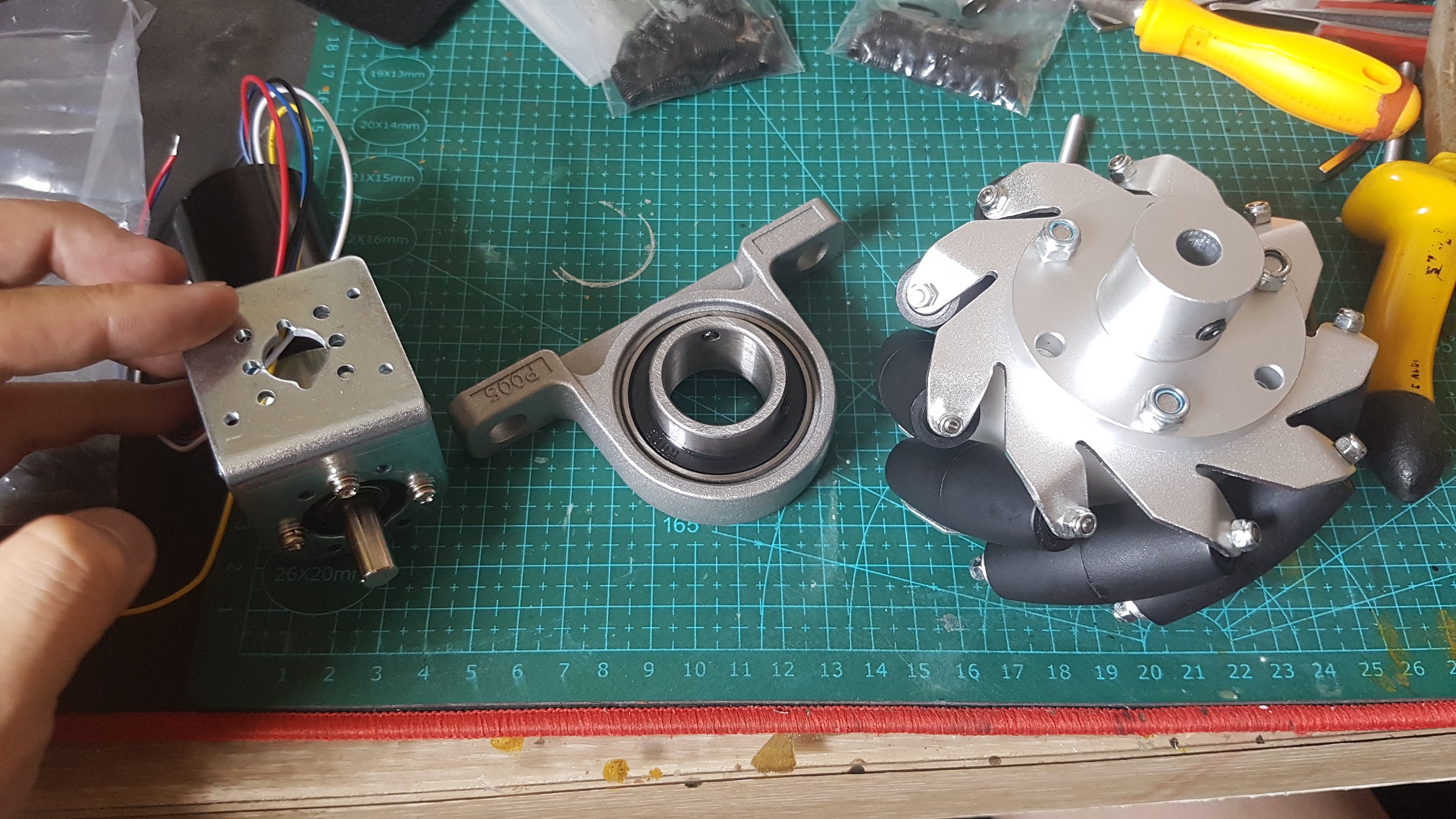
Mecanum wheel coding:

The Mecanum wheel is controlled through a 5 wire motor(VCC,GND,PWM,Dir and FG wire) so the motor driver was not required and I could wire them directly to an arduino. all the code was stored and run through an Arduino Uno whereby the main switch to control the motors were linked to a relay for the motor circuit. As mecanum wheel move unlike a normal wheel, special codes were used to move the robot in any direction without changing the orientation.

Image result for mecanum wheel control


Master-Slave Arduino System

There is a function of Arduino that is called the master and slave relationship, whereby a master arduino could communicate with other arduinos(up to 52) through just two analog pin (A4 and A5), this is really helpful for my robot as there was the saying of “Do not put all the egg in a basket” and this function will ease my repair if any parts gets faulty during the FYP show, I could just switch out the problematic parts without re-wiring the WHOLE 5 bazillion wire connections. Also, Arduino is a single thread micro-controller(it can only do one task at a single moment) so by splitting up different processing requirement into different arduino, I could run multiple thread without any lags between them. Finally for the upside of a Master-slave system, it is simply to solve the problem of hardware problem of the limited digital pins each arduino have(more arduino = more pins I could utilize without having more parts/coding like using a I2C Address chip.

wiring diagram

Things are getting technical here…
The Wiring Diagram, as messy as it looks but in normal language, a Master Arduino is controlled by a clickable analog stick (mode 1 to move, mode 2 to rotate), the data is processed and sent over through Analog Pin 4 & 5 to the MPU and EPU which “Movement Processing Unit(MPU)” that controls all the movements of the motor and “Emotion Processing Unit(EPU) controls the eye Animation on the LED Matrix. All of the Arduinos and motors will be paralleled connected to the 12V battery supply to power them up.


O.U.R.S Chief Engineer at work:

Sample Movement of Explorer 27:


FYP Process 4: Construction, Unity and Lidar

Aluminium profile measuring and cutting

20mm*20mm aluminium profile was used to construct the internal frame because it is easy to work with, lightweight and durable.

(Just for the record, I did not work in the dark but turned off the light for documentation purposes only.)

3D Modeling

This is the mounting adapter created in tinkercad to match the steel bearing, the motor and the wheel to the 20mm*20mm aluminium profile. the adapter for the suspension was created later as the suspension had not reach at the time of modeling the mounting adapter, however the 3 part fit nicely with just one try!

3d printing

Frame constructions and 3D printing part assembling.

many different screws, bolt and nuts were used to construct the frame and attach the wheel mount on the aliminium profiles.

Suspension Addition

The suspension is required as the Mecanum Wheel require friction to move in any direction, so the suspension does not only reduce the vibration, but to force the wheel to have traction with the floor at any point of time even on uneven surfaces.

Unity:
Animation done in Unity,

IlSample quest screen (there will be another screen to show the map or something)

These 3 were drawn in Adobe illustrator in separate layers and imported into unity to animate it.

Lidar:

Lidar uses infared laser to sense the distance in a 360 degree manner, it could give thousands of readings per second and the program will calculate them and map it out through a point cloud.

I bought a Lidar from China to try it out and the 1 I bought was C0602 

when using the program that was provided, the lidar works perfectly, but since I am going to use it in Unity, there are problems as Unity runs on C#(a programming language) while the SDK(Software Development Kit) runs in C++, although it is not impossible to write a bridge between the 2 language or write another code in C# to use the Lidar directly in unity, it was out of my capabilities to do so after trying for a week, and while researching for how to do it, i came across another Lidar that provided the Unity codes, however the code does not work on the current lidar I have……

SO, simple solution to this problem, either i ditch the idea of using a lidar OR I buy the Lidar with the Unity code and I put the current Lidar I have for sale online (at higher price than I bought it of course.) And of course, I chosed the 2nd option, to sell the one I have and buy the other 1 that provide a unity code. Carousell, my best friend.


FYP Soul – Why?

Why robot? Why Guiding robot? Why a whole system including a company, a backstory of how the Robot came to FYP exhibition?

First thing first, Why am I building a robot for FYP?

The answer is much more than just because I like it (and of course I do!)
Culturally, there are two opposing opinion of a robot – A western one which threaten us by stealing our and eventually bring us to annihilation, A Japan one which is seemed as hero and seemed to enhance the quality of life, since 16th century after the invention of karakuri puppet, the Japanese enjoys seeing something moving automatically and it is still really fascinating to see something that moves by itself now as we anthropomorphize the object unconsciously. I personally think that robotic will be the next advancement to the world as our computation power increase exponentially, the only physical way we could bring these newer technology into a good use is through something that uses technology and have a physical/tangible characteristic, just like a robot, albeit the term robot was loosely used, the general idea is similar- Physical object that moves without human through a set of pre-determined  protocol.

so, why specifically a guiding robot?

This is because I want to be of some use to our FYP batch, Guiding robot’s main purpose is to serve just one function- to bring the visitor to a student booth, which will increase the exposure of the student. Even if throughout the whole show duration, my robot only managed to bring one visitor to one student’s booth and the visitor enjoyed the booth, I would consider my FYP a success as I helped someone(visitor or student) to experience the FYP show in a slightly better way.

How about a lost guiding robot?

For now, I will be building a lost guiding robot which need the visitor to help to locate the student’s booth, although it seemed counter-intuitive to make a LOST Guiding robot as the worst thing that a guiding robot could do is to get lost, however when I go the opposite way(metaphorical), the end result still serve the same function, a robot which guide(narratively, it will be guided) the visitor to the booth. This way, the user experience/interaction with the robot will be different as they will feel like they will be helping the poor robot to find and complete it’s task and the visitor will feel like they have a sense of duty/accomplishment when finding the booth.

How does this work?
All of these stems from the word “Altruism“- the belief in or practice of disintegrate and selfless concern for the well-being of others. In this case, sacrificing the user’s own time to help a random robot.(which by logical thought, they do not need help and does not have feeling, however human is a complex thing and probably will not do things by logic)
As helping others will give us a sense of purpose and satisfaction, I will want to instill this idea into my project to make the user to feel like they are really helping the robot and feel the satisfaction when they complete the task(which in turn makes a happier visitor and a memorable experience for them.)

Why a whole system including a company, a backstory of how the Robot came to FYP exhibition?

This is to adapt the power of fictional narrative to change people’s attitude towards social change(robot in FYP exhibition) by using the method of narrative persuasion- a method that uses narrative transport to persuade us to change our mind, behavior and see the world differently and to put things into context even when the story is a fantastical.


Research to be done:
Interaction of human and robot
Social Robot
Programmed behavior
Slot machine reward system


https://topdocumentaryfilms.com/human-robot/

https://topdocumentaryfilms.com/inhuman-kind/

https://topdocumentaryfilms.com/robot-revolution/


FYP Process 3 – rebranding: O.U.R.S. + parts and systems

Changing Project title and Styling

As inspired from the trip from Japan, I decided to change the theme/styling of my FYP from a futuristic company(Hephaestus System Link 1 & Link 2) to a Tech Company in a Cyber Punkish Futuristic world, and after giving in depth thoughts about the branding of the tech company, I came out with “O.U.R.S” the acronym for “Omni Utility Robotic Systems”. There are many reason that this will be the perfect title for my FYP because the original idea of my FYP is to build something that could help out with all of  FYP student’s FYP exhibition, so “OUR” Robot fits the bill perfectly. Furthermore, I am changing the moving System from a simple robot that moves like a remote controlled car(only front and back with turn) to a Omni-Wheel System(Mecanum Wheel) whereby it could also move diagonal/sideways without changing the orientation. “Omni-Utility” could  both meant Omni wheeled robot with practicality and multi-utility robots with many functions built into it, “Robotic systems” was on the same idea with the previous “Hephaestus Systems” I do not want to only create a single robot, I wanted to create a system whereby that robot is only part of the system. So Omni Utility Robotic Systems (O.U.R.S) will probably be the name for my (Imaginary) company as well as the title for my FYP.

Logo Design:

With a Picture I took in Japan, Tokyo, Shibuya Crossing as “Mood Board”

Improved Unity UI(Slightly)

added a simple(sample) animation with the standard UI, buttons and back buttons work fine,(the actual animation is much smoother, but the GIF is slow)

Unity-Arduino Control

I learnt how to use unity to send Serial output to Arduino, although it was quite easy, but it took a really long time for me to figure out how it was done.

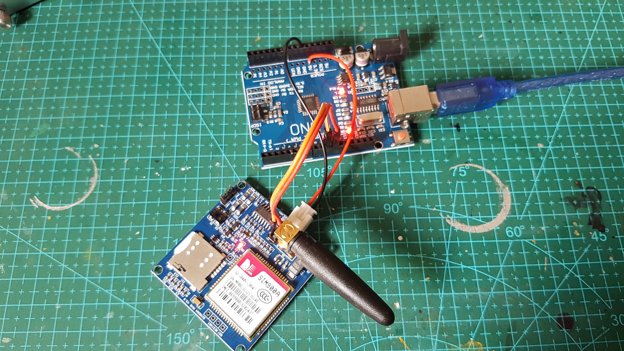
The arduino code was written in a way that it gives multiple values in a < > bracket as start and end marker, so that it could be changed to spin the motor and sms the student through arduino in the future, example of the serial communication <255,255,255,255,(phoneNumber),(UsersMessage)>

New Parts, New Systems

I had decided to build ONE robot instead of TWO robot at this point, so my total budget for building the robot just X2 instantly, this was the reason that I am changing the idea of using the kids vehicle to using Mecanum Wheel because it will be much more impressive.

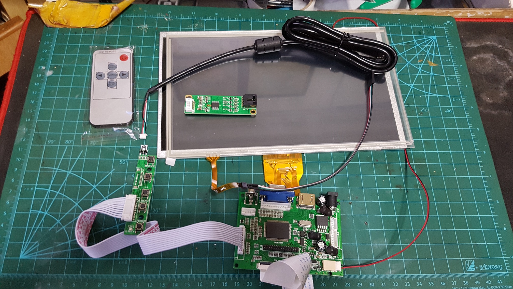
This is a 11 inch screen with HDIM driver with a separate touchpanel, however the seller sent me the wrong usb wire so I cant test the touchscreen before they replace it, however the screen works well! although it is abit small, but it is good for my budget and power issue (my robot will run with internal battery so every component used in it must have their power consumption taken into consideration before everything.) 

The 2cm*2cm Aluminium profile reached and I measured the size i will probably need as the base frame of the robots.
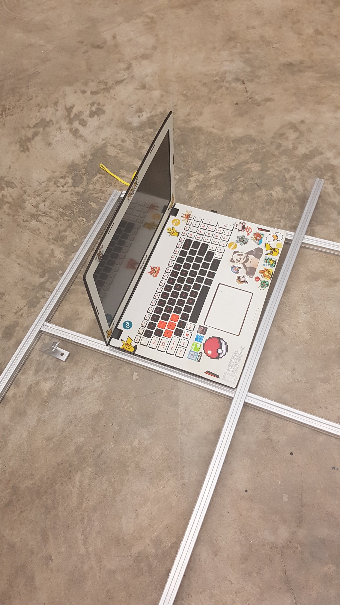
The largest single component in the robot will be the laptop which will be used to run the calculations within the robot so the minimum base size will be atleast the size of my laptop (the wheels will be protruding the frame so tha actual base will be about 15cm wider) I’ve cut the profile to form 47cm by 40cm(+~15cm for wheels) currently and I might make changes along the way.


For the SMS system which will be in the robot for the visitor to leave a feedback directly to the student, I’ve purchased a Sim-card along with a SIM900A module which enable Arduino to send SMS through the SIM card.
After sometime of trying the SIM900A module out, it does not connect to the service provider and I did the research about it and apparently this module only uses 2G from the simcard, and Singapore had phased out 2G service, so this module was unable to be used in Singapore, therefore I had to purchase another better simcard module which supports 3G/4G(and they are rather expensive but I had to do it…)

It could change direction then the direction change wire is connected to the ground. Powered by a 12V battery, Arduino Uno and a PAC9685 servo driver.

Mecanum wheel and the Motors will probably be the most expensive components in my whole robot(other then the laptop which I already have) as I purchased the best valued component, not the cheapest, an industrial grade aluminium CNC Mecanum wheel(10cm diameter and capable of handling 45KG load) to make sure they will last at least a year plus a month of exhibition time. The Motor is a high torque (8kg/cm *this is torque, not the load it could carry*) and can do PWM speed control, Speed Feedback and Breaking system built into it.
So although the price, I had gotten the best possible combination of parts with my given budget.

Have you ever wondered what a freelancer could do for you?

I thought of this as a joke(or potentially useful for my FYP), but what if I could have someone to draw my initial concept for me to have a starting point to develop my robot?

Since asking people to do it for free is not something which I prefer, I came to fiverr to find character design gigs just for fun, after asking multiple seller about what they could do, I found one potential one.

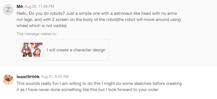
Of course I had no expectation to have something that I could use as a final, but it would be really cool if I can see a work created specially for my project… and I gave a super vague brief to the artist on purpose because I just wanted to see what kind of weird ideas I could get, and if there are any ideas good enough, I will just adopt into my robot!

So after half day or so, the seller delivered the drawing I requested.

It is really cute and definitely not something I would use, It look like a cardboard robot and is not what I would like to build, but well, it is really funny and refreshing to see my potential “robot” to go for picnic alone!

I shall just start thinking about the design on my own(afterall I had done too much reference research from existing artwork hence this weird idea of getting others to draw me a tailored robot.) and take advice from my friends around me and not do weird stuffs online.

Other Inspirations:

Is the time of the personal robot coming of age?

FYP Process 2 – Research in Japan

During the holiday, I went to Japan and did research as the first country that I would think of robotic will be Japan as they are really advance and I really love the styling of the way they built their robots (digitally or physically) as I grew up watching robot anime like Gundam.

Japan was awesome in technology, toys, and food!!

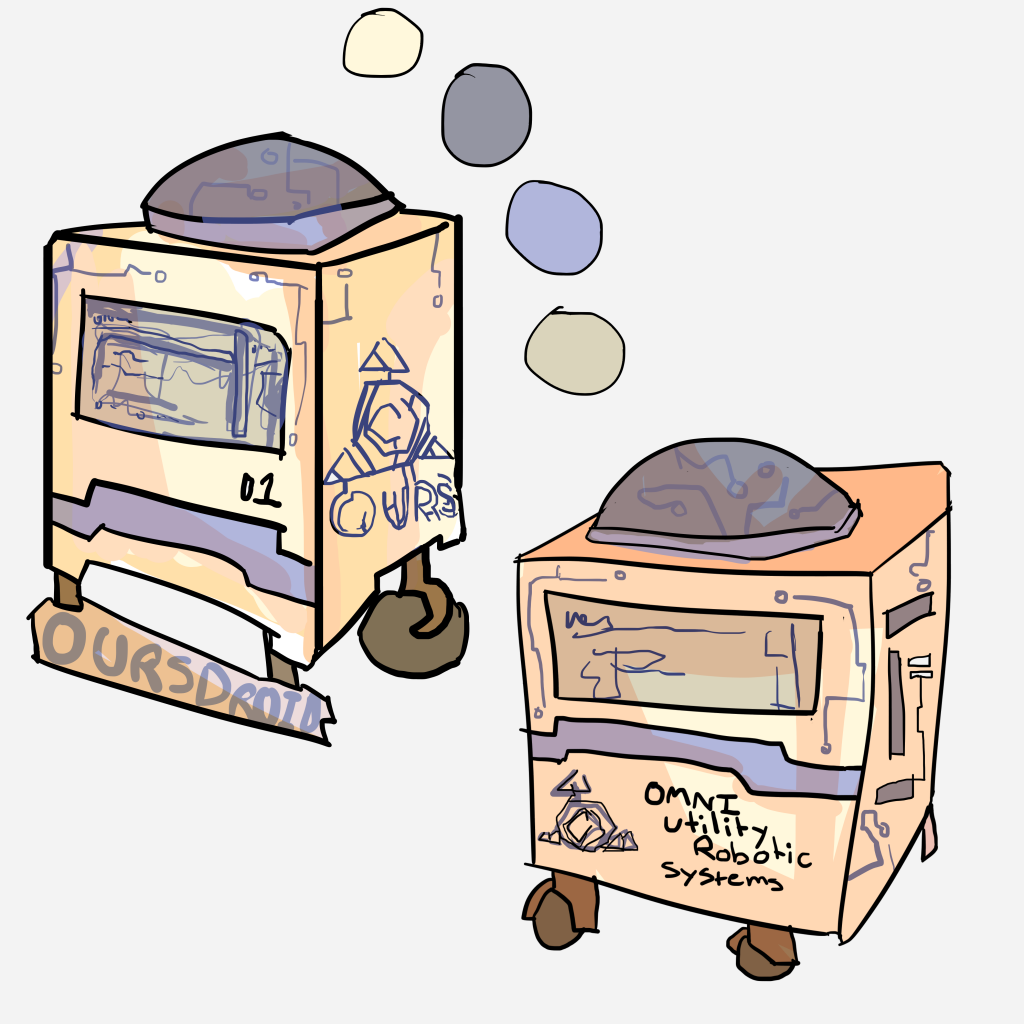
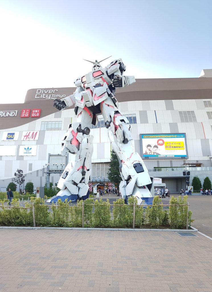
The Gundam outside Odaiba, Tokyo, I really like the styling of Gundams.

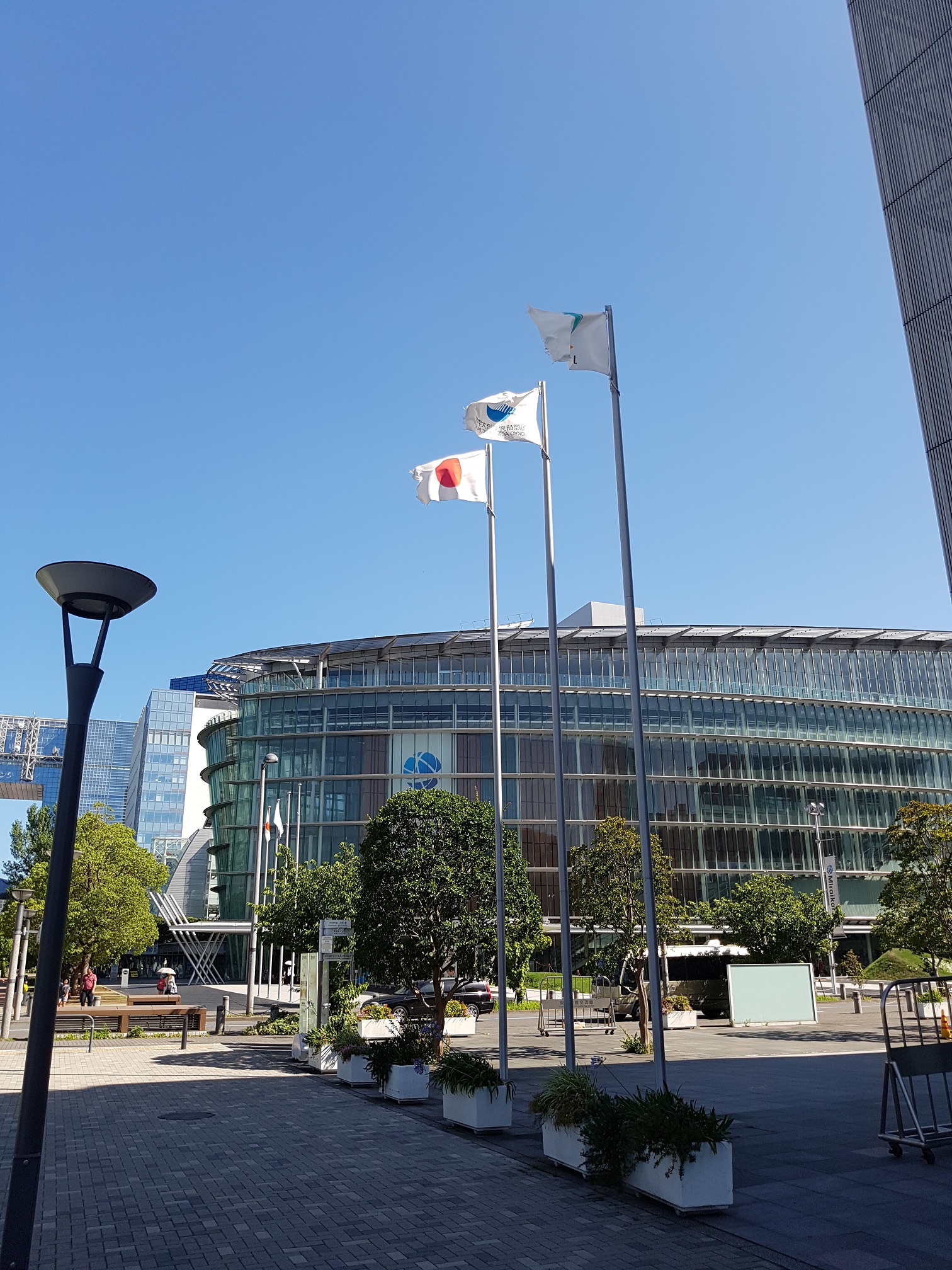
This is the The National Museum of Emerging Science and Innovation (Miraikan) of Tokyo.

the iconic location of Miraikan, i am amazed by the scale of it.

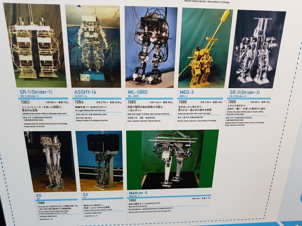
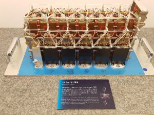
Upon entering the Museum, I was greeted by one of the robots, its really cool to see the “undressed” robot so that i can take a look at the constructions and the system they were using. cool stuffs!


this personal vehicle was made by Honda which could carry the person, much like an hoverboard but the sitting version, the visitor could try it buy i missed this activity if not i would really love to try one.

The main purpose I went to Miraikan, to see the famous Asimo, its really cute and i love the astronaut-styling it has. i must say it was really well made and it can dance and kick a ball, although they are pre-programmed, its still inspiring nontheless.

there was this touch screen which display the details of the globe over there and explain the stuffs on it, since I am also using UI in my robot, this was the futuristic style I had in mind, black background with bluish outline that has the advanced feel to it.

The history of Bi-pedal Robots


I was inspired by the space exhibit and thought that it was really cool to build my robot with a space+futuristic theme as I like that style alot.

many of the exhibits in Miraikan was screen-based installation which was not related to FYP other than those that was in the post, however they were all amazingly made and really impressive.


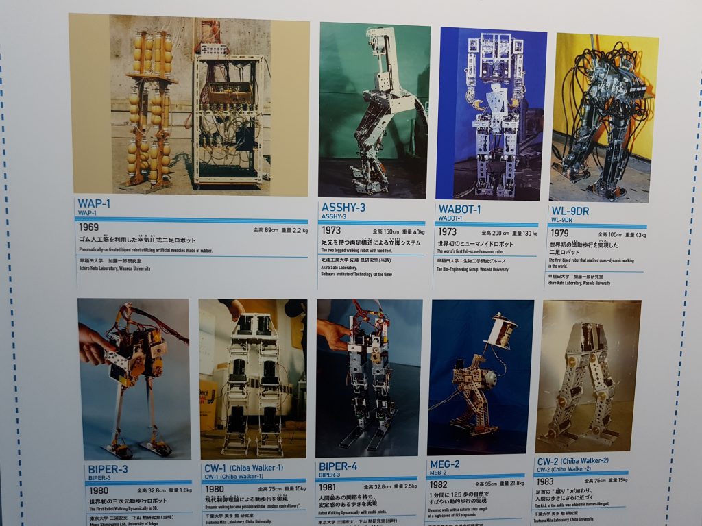
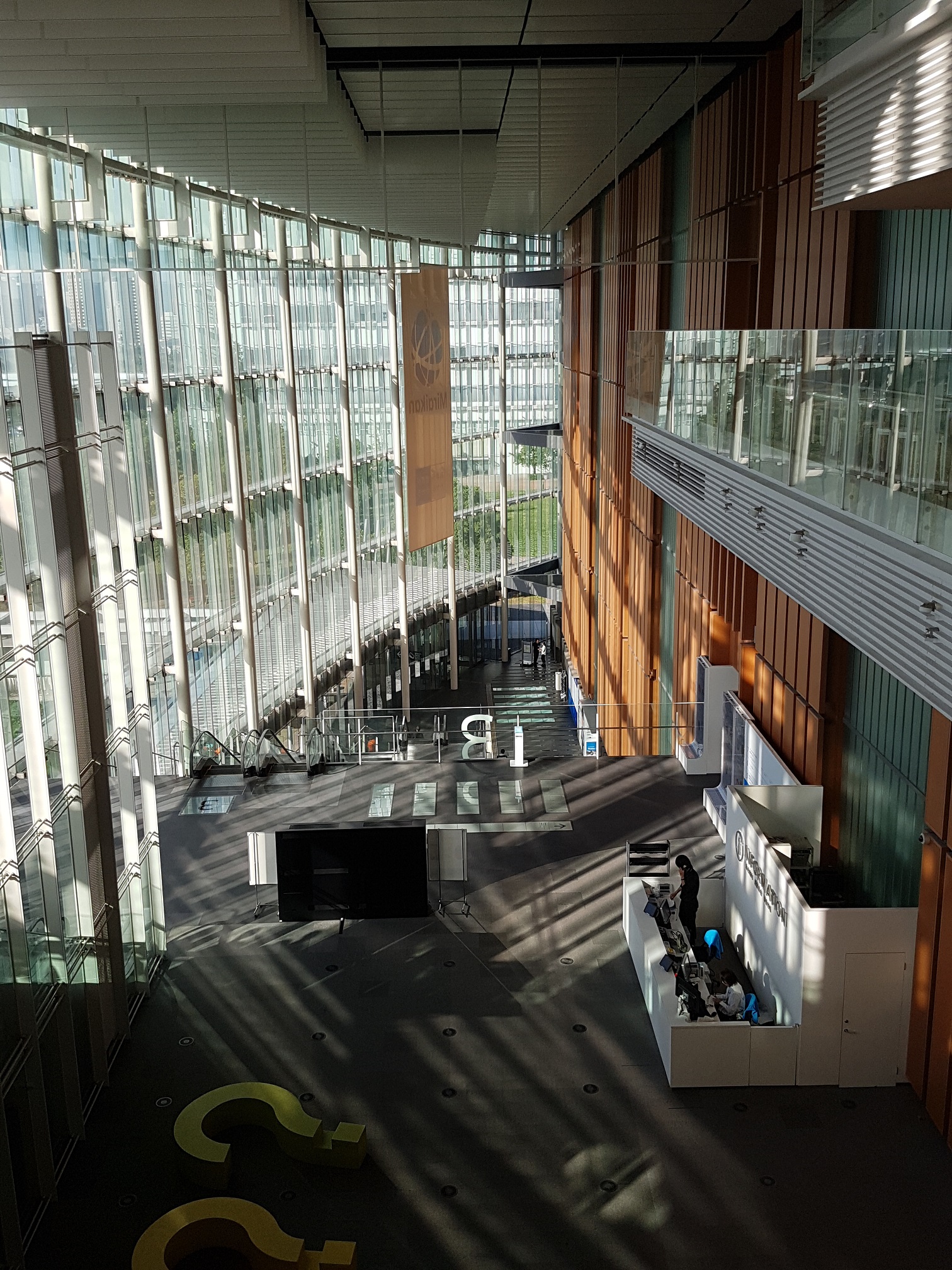
Internal of Miraikan.

and I really like Asimo so i bought one figurine which was rather expensive but it will work as a exhibit for my FYP booth.


FYP Process 1

After many different trials and setback, and after going through many online courses for Visual Studio which I initially wanted to use it to create the interface for the robots, Senior Kapi suggested to me to use Unity instead as it will be easier to do a nicer graphical interface(Visual Studio will just be hard to make beautiful UI from all I went through) and is able to do advance AI like path-finder which I might use it in the actual robot for navigation, Also, Unity is better in Particle system which I will use to create animation for the UI and so, I gave up the idea of using Visual Studio for the back-end programming, and while going through the tutorial of Unity, the scripting side within Unity was still in Visual Studio, so my effort in learning Visual Studio wasn’t wasted because it incorporated well into the Unity system.

To start off prototyping, my target: To create a page that is able to change the image and text by clicking any of the buttons placed within a scroll-able panel.

This will be required as the final product would enable the user to browse the student’s information and work, there should be a easy to use User Interface that allows them to do so.

The course which I went through:

https://www.udemy.com/c-sharp-visual-studio-app-development-tutorial/

The course which I am currently going through:

https://www.udemy.com/unity-master-video-game-development-the-complete-course

https://www.udemy.com/robotics-for-beginners-build-time-control-robot-from-scratch

Additional Tutorial.

https://unity3d.com/learn/tutorials/modules/beginner/ui/ui-scroll-rect

https://unity3d.com/learn/tutorials/topics/user-interface-ui/ui-scrollbar

https://unity3d.com/learn/tutorials/topics/user-interface-ui/ui-mask


Current Progress:

this is a gif, click to play


After thinking about the problem of the robot’s sensing(i must try not to have the robot to knock people down.) I was considering about Lidar for a long time but the price and the spinning part was the main concern that put me off, it cost around $150 for just one sensor which I am not confident if it will even work in my project, also because it is the Lidar which spins, it meant that it have to be placed on top of the robot and I am sure that it will break somehow due to visitor’s curiosity. After whole lot of research (I will still use ultrasonic/infared sensor like we did in class, but these are not reliable and cannot be the primary sensor) I came across something that seemed really promising… let me introduce to you, the old KINECT.

Why? Why Kinect? because..
1- it does not have moving part yet it is able to detect a wide area with roughly accurate distance.
2- it is easy to be concealed in the design of the robot as it could be place within the shell.
3- it is not expensive and I already have one unused Kinect at home, futhermore if I need more, the school have them.
4- USB operated means I do not need to find additional adapter/converter to use them.

Sounds good, the problem is, I don’t know how to use them and the documentation i found are not for what i need so i need to do further research.

………………………………………….

The following day, I went to school to loan the kinect from school and after some research which says it will not work on windows 10… I finally found some that mentioned that it is possible.

So TADAAAAA!

now I need to find a way to plug the data into Unity for then it will be possible to use it as a distance sensor..
(On the side note, I found that Kinect V2 is much better as it has wider field of view so I might consider that too.)


Children toy-Wheel System

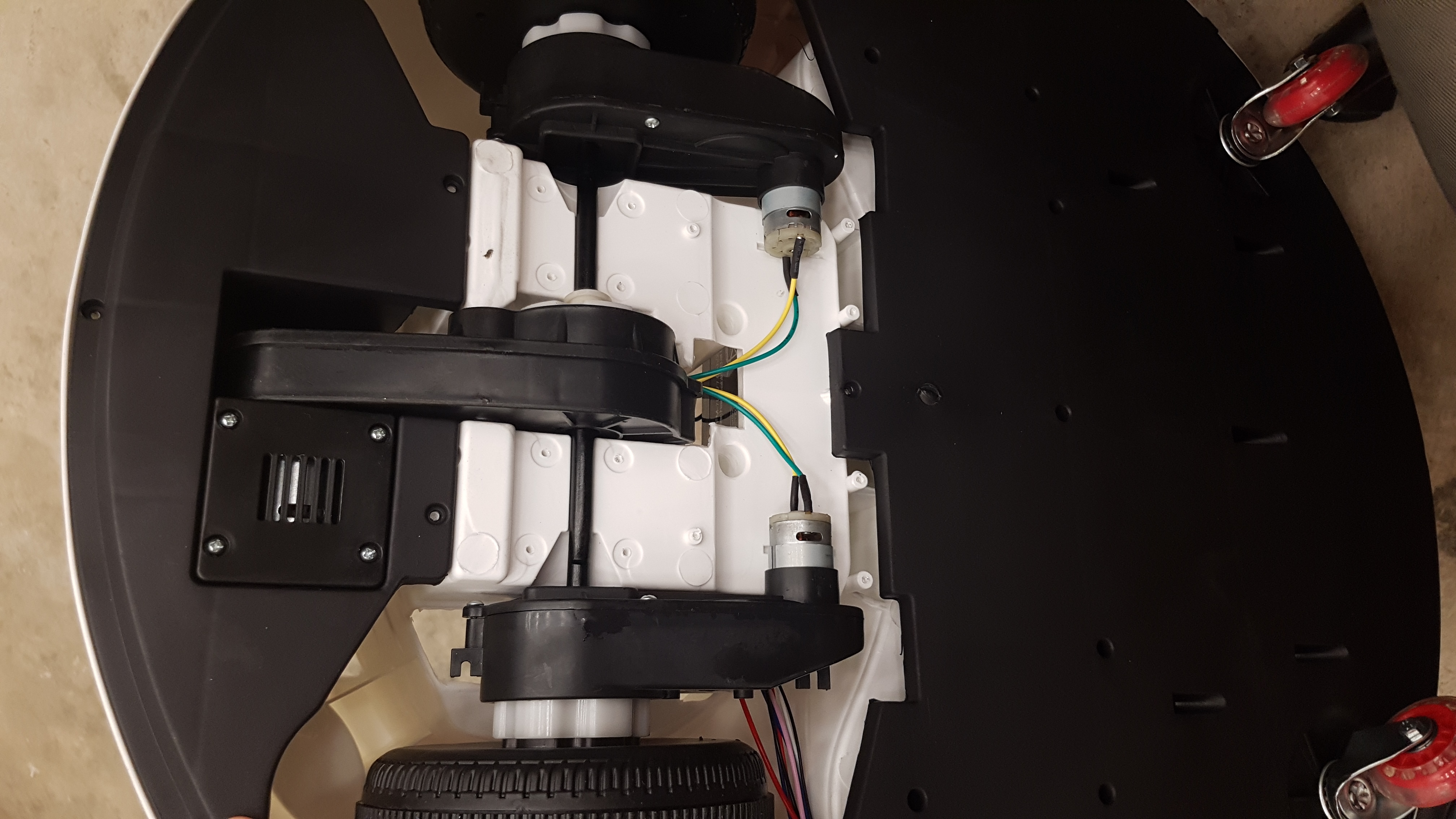
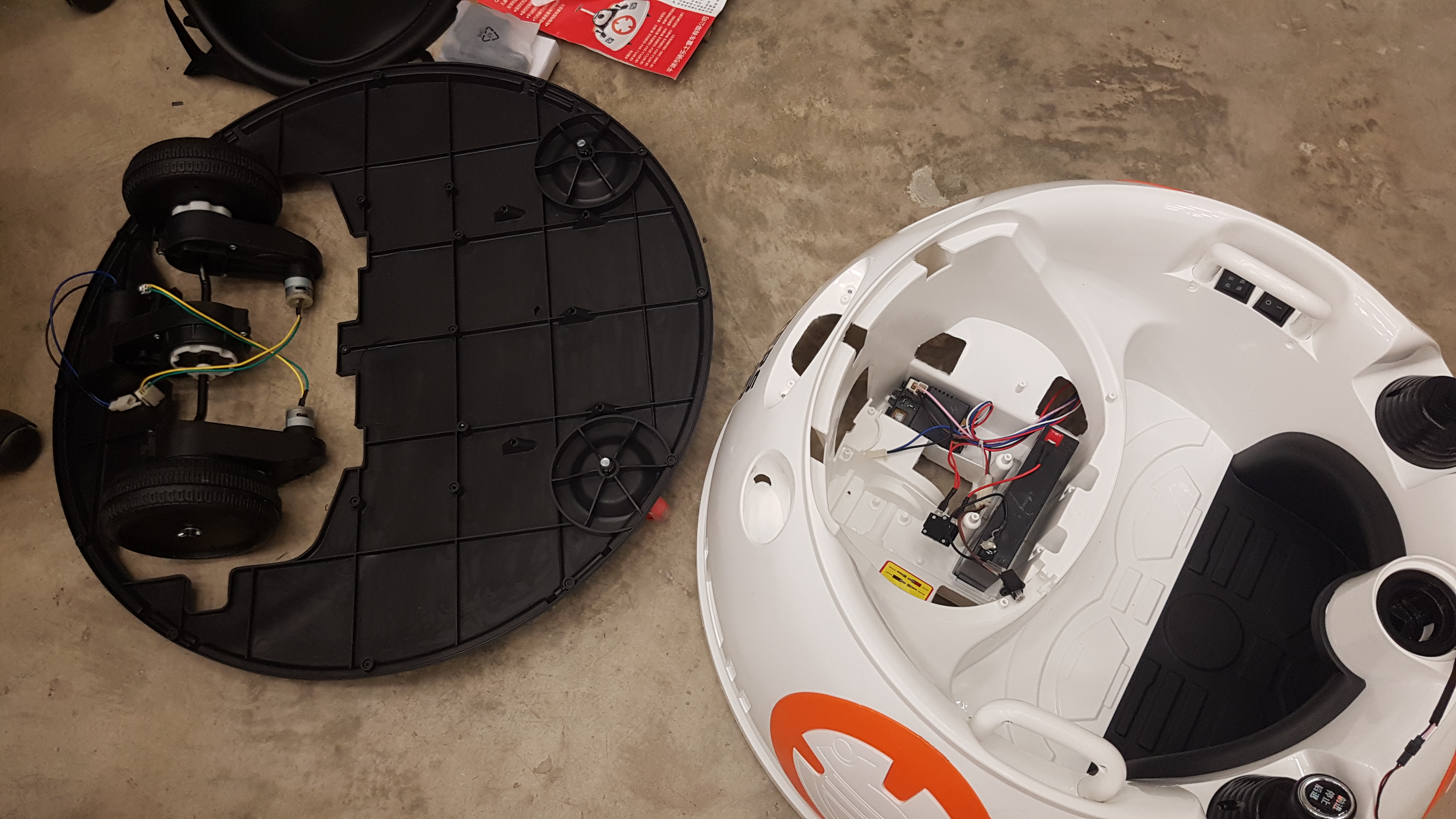
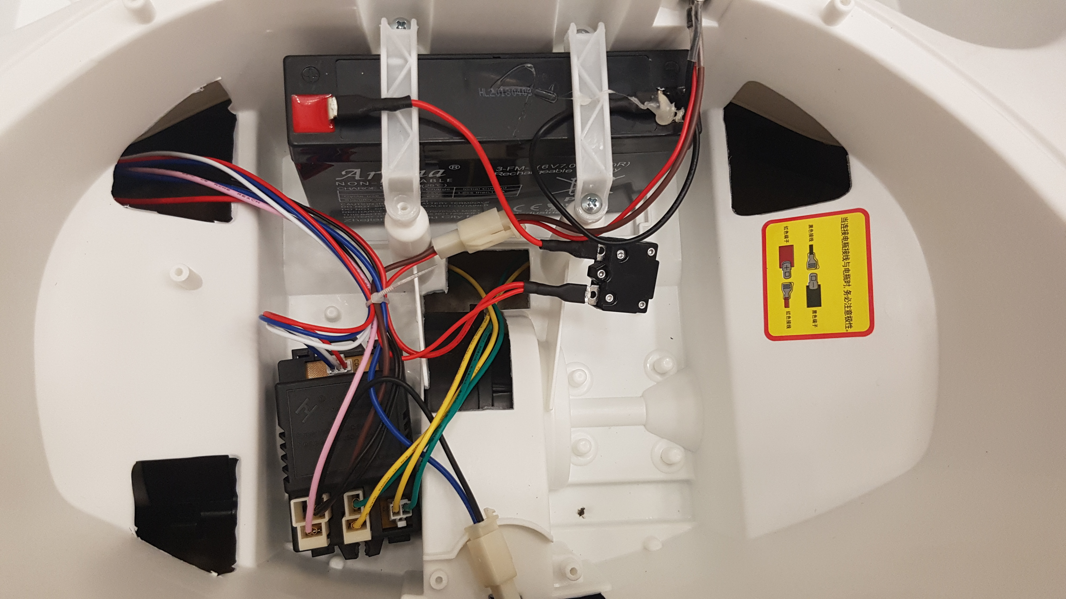
Remote Controlled Children vehicle, it can take up to 30KG hence I bought this to use it as a base since it will be able to carry all the components.

Just for the record, this thing cost $103.51 with $2.99 for shipping fee from china (used EZ-Prime hence the cheap shipping), i think that the overall value is so much higher than the cost, I will take it apart and use the components within it and discard the BB-8 theme plastic case.

Interactive spaces: Light and Darkness Ver.1 – Analog

after the previous process, process 3

Thanks to Tiffany and Joan for the awesome snippets that were used as the featured image as well as in the videos, and helping with lighting up all the candles + documentations.

Also Thanks to Bao, Fabian and Suhwee for helping me to place all the candles onto the candle platform.

I’ve seen the actual project with real candles in the dark room the first time as the class saw it.

Light & Darkness was created to give a sense of alternative space within an ordinary space, in this project, I wanted to create a space so that the audience will forget that they were in the IM room, the room was build with pure darkness and stability in mind as nothing should collapse as I wanted to hang the candles platform instead of building a table-like structure to give a sense that all the candles were floating in space(which is also the reason why everything, including the candles platform was black), this worked really well as the candle platform would swing gently which increased the magical feeling to my space, Also, all of this will be enhanced in the digital version as I would add a series of stars(LED, not projection) to the room’s wall to increase the feeling of enchantment. The smell of the candles, as well the burnt smell created when extinguishing the candles worked much better than I expected, as I wanted to have smell that is not too overpowering, I’ve used 239 unscented candles with 60 scented candles, this combination worked like a wonder because there is only a faint smell outside of the dark room. another point that worked better than I expected was the random placement of the scented candles created a colourful candle array when they were all lighted up and this increased the overall aesthetic of this project’s analog version greatly.

After this analog version, I’ve noticed a few points to take note of, it is actually quite hard to light up all the candles so more lighters will be needed and the current lighter that I was using appears to be rather difficult to be used, so I’ll probably buy some more lighter which is much easier to be operated and uses lesser strength. Also, I would have to paint the metal wires that was used to hang the candles platform into matt black as the metallic would reduce the magical floating aspect of this project.


Drone Flashing + calibration

To be able to flash, open Betaflight home page and install the 2 driver software/updates:

  1. zadig-2.3
  2. CP210x_Universal_Windows_Driver

update both driver to WinUSB (v6.1.7600.16385) in Zadig

then load the firmware (Betaflight F4 V2.0) to the drone by holding the bootloader button on the drone, plug in the micro usb, then flash the firmware into the flight controller, all while holding the bootloader button on the drone.

if unable to connect to the betaflight after flashing, it meant that the driver is in the wrong setting, follow this tutorial to change the device driver to “Microsoft USB serial port”

after that, reconnect the drone to beta flight and it should connect.

If the Throttle and is reversed(up is lower value and vice versa), simply open the battery cover of the controller and push the channel 3 switch up.

after calibration of the esc, this is the setting for now

My Resume+ Artist Bio

Ong Zi Feng
(+65)9698-1684 | pod_ozf@hotmail.com | ongzifeng.wixsite.com/portfolio(WIP)

I am a seeker in the world of skills, opening doors of differing practices in pursuance of proficiency in various field of design in the hope to find the abilities to change the world into a slightly different place.

Artist Bio
Ong Zi Feng is an artist with a spirit of entrepreneurship and a passion for creating things by hands. He developed interest in design at a young age when his father taught him to draw. He is thankful for the encouragement his kindergarten teacher gave him by praising his ugly drawing of a dog. Throughout his primary and secondary school education, Zi Feng spent more time doodling in his textbooks than studying. His Chinese textbook was the saddest victim of vandalism, filled with correction fluid while the figures in it were often given special makeovers. 

After his Secondary School education, Zi Feng decided to pursue his interest in product design and spent an enjoyable three years at Ngee Ann Polytechnic’s Diploma in Product Design & Innovation. After graduated from Polytechnic, Zi Feng was enlisted into the National Service and was posted to Tuas Naval Base as a Military Police Specialist which he spent all his saving from National Service into two solo backpacking trip, first was a two weeks trip to Taiwan and then a two month trip to Cambodia, Vietnam, Laos, Thailand and Malaysia. The solo backpacking trips had taught Zi Feng many invaluable lessons and changed his perspective of how he views the world, the people and in himself.

As an aspiring entrepreneur, he started a small business, WindCustoms in Etsy in hope of fulfilling the childhood dreams of others by focusing on selling handmade collectible items inspired by movies and animes from Zi Feng's childhood.

Trip Video:
Long Trip Home
Education
Bachelor of Fine Arts in Interactive Media
Nanyang Technological University, May 2019
 - Dean’s List, 2017
 - Dean’s List, 2016
 - Platinum Award in PS9888 Making and Tinkering, 2016

Diploma in Product Design and Innovation
Ngee Ann Polytechnic, May 2012
 - Director’s List, Apr 2011
 - Best Performance in Product Form & Aesthetics, 2011
 - Best Performance in Computer-Aided Design & Drawing 2, 2011
 - Oversea exchange to Jiang Nan University twice
 - Director’s List, Oct 2010
 - Best Performance in Design Specification & Conceptual Design, 2010
Professional Experience
Self Employed
WindCustoms, Etsy, 2016 - current
 - Sole proprietor of the shop WindCustoms on Etsy which sells collectibles in hope to fulfill the childhood dreams in us.
 - Communicated with numerous customers, negotiated with organizations and suppliers
 - Designed and produced all orders which includes customizations according to
 customer’s specifications and deliver them punctually in perfect conditions
 - Organized campaign for online advertising.
 - Amassed more than 1,500 sales and 200 5 stars reviews in 2 years
 - Awarded with Bestseller item and Top 5% Seller on Etsy in 2017 and 2018. Military Police Specialist (NSF)
Tuas Naval Base, June 2013 - Sept 2014
 - Illustrate and design the schematic and system of the Personnel Access Control 
 which improved the flow of traffic in the morning while enhancing the security.
 - Designed a makeshift shelter for duty outpost which improved the life of the
 duty personnel by preventing them from getting drenched every time it rained.


Additional Skills
 - Proficiency in Adobe Creative Suite (Illustrator, Photoshop, Premiere Pro)
 - Working knowledge in Unity, Zbrush, Rhinocerous, SketchUp and Audacity
 - Experienced in model building, sculpturing, airbrushing, 3D modelling and printing
 - Competent in Arduino, Raspberry Pi, Latte Panda and Beaglebone
 - Working knowledge in C++, JavaScript and PHP
 - Fluent in Chinese and English