Why robot? Why Guiding robot? Why a whole system including a company, a backstory of how the Robot came to FYP exhibition?
First thing first, Why am I building a robot for FYP?
The answer is much more than just because I like it (and of course I do!)
Culturally, there are two opposing opinion of a robot – A western one which threaten us by stealing our and eventually bring us to annihilation, A Japan one which is seemed as hero and seemed to enhance the quality of life, since 16th century after the invention of karakuri puppet, the Japanese enjoys seeing something moving automatically and it is still really fascinating to see something that moves by itself now as we anthropomorphize the object unconsciously. I personally think that robotic will be the next advancement to the world as our computation power increase exponentially, the only physical way we could bring these newer technology into a good use is through something that uses technology and have a physical/tangible characteristic, just like a robot, albeit the term robot was loosely used, the general idea is similar- Physical object that moves without human through a set of pre-determined protocol.
so, why specifically a guiding robot?
This is because I want to be of some use to our FYP batch, Guiding robot’s main purpose is to serve just one function- to bring the visitor to a student booth, which will increase the exposure of the student. Even if throughout the whole show duration, my robot only managed to bring one visitor to one student’s booth and the visitor enjoyed the booth, I would consider my FYP a success as I helped someone(visitor or student) to experience the FYP show in a slightly better way.
How about a lost guiding robot?
For now, I will be building a lost guiding robot which need the visitor to help to locate the student’s booth, although it seemed counter-intuitive to make a LOST Guiding robot as the worst thing that a guiding robot could do is to get lost, however when I go the opposite way(metaphorical), the end result still serve the same function, a robot which guide(narratively, it will be guided) the visitor to the booth. This way, the user experience/interaction with the robot will be different as they will feel like they will be helping the poor robot to find and complete it’s task and the visitor will feel like they have a sense of duty/accomplishment when finding the booth.
How does this work?
All of these stems from the word “Altruism“- the belief in or practice of disintegrate and selfless concern for the well-being of others. In this case, sacrificing the user’s own time to help a random robot.(which by logical thought, they do not need help and does not have feeling, however human is a complex thing and probably will not do things by logic)
As helping others will give us a sense of purpose and satisfaction, I will want to instill this idea into my project to make the user to feel like they are really helping the robot and feel the satisfaction when they complete the task(which in turn makes a happier visitor and a memorable experience for them.)
Why a whole system including a company, a backstory of how the Robot came to FYP exhibition?
This is to adapt the power of fictional narrative to change people’s attitude towards social change(robot in FYP exhibition) by using the method of narrative persuasion- a method that uses narrative transport to persuade us to change our mind, behavior and see the world differently and to put things into context even when the story is a fantastical.
Research to be done:
Interaction of human and robot
Social Robot
Programmed behavior
Slot machine reward system
again, I had progressed much further since that post, mainly in designing the workable electrical and mechanical system that could fit into the Telephone and to write the Arduino code up.
First, lets start with the Final Video!
Back into the Process
Since the previous post which I’ve roughly did the belt system that drives the music card into the laser reader, I had added the motor to the system and tried it, at this point, it seemed to work as I thought all I need was to slow the motor down and it will be alright.
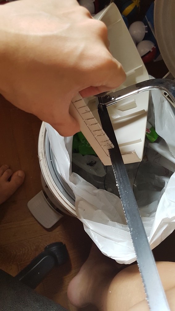
First I sawed the phone to remove the material for me to cut them easily later
and slowly, I cut them up
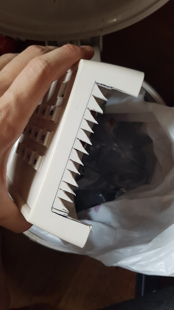
after chipping the plastic off, i constantly checked the dimension of it and trimmed a little at a time to prevent having a larger hole than I needed.
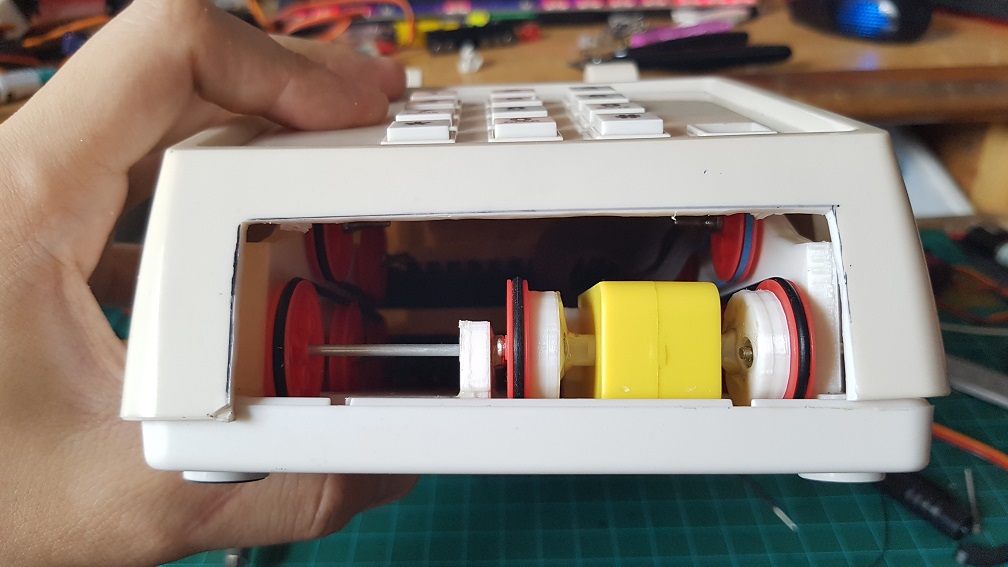
With this hole, I could finally see how it is looking internally and if there are any parts i made which was too tall in the case.
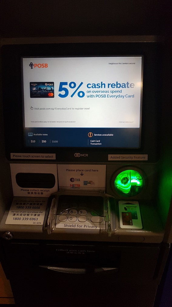
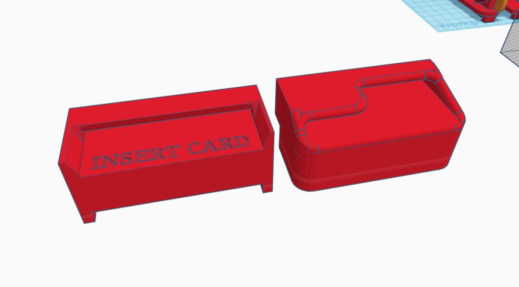
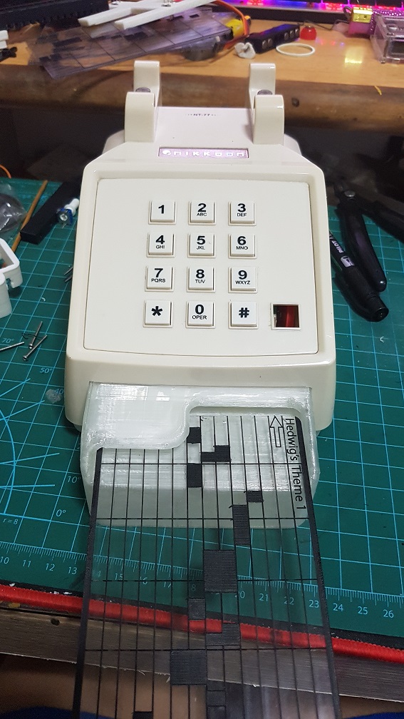
After I cut the hole, I proceed to modelling the card slot and i took inspiration from the ATM just to have the user to have something they’ve experienced and know how to put the Music Card in without instructing them, since subconsciously, I assumed that they interacted with a ATM at some point in their life.
This is the inspiration that I took from
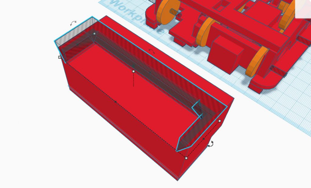
I used Tinkercad to modeled it and the cube like doesnt look like ATM card slot.
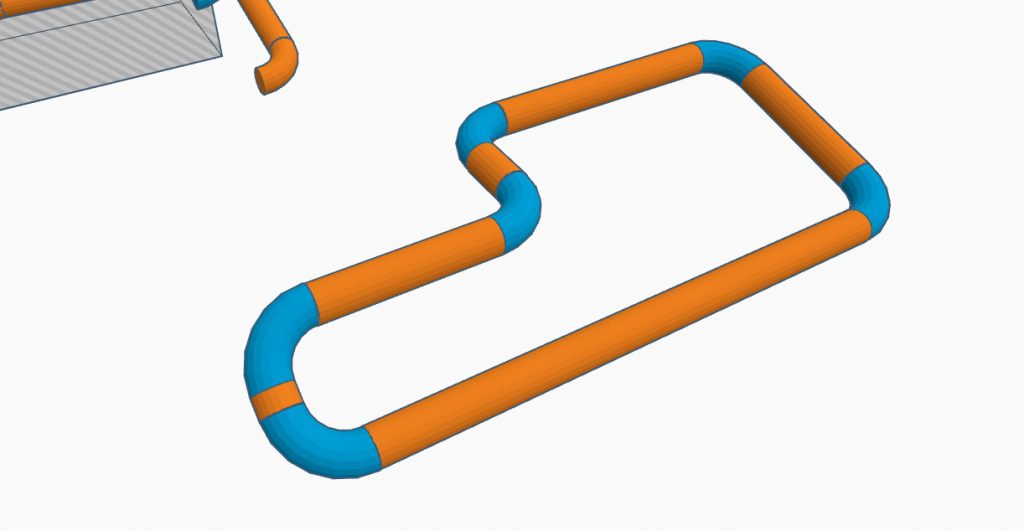
so i tried to use curve lines, and MANNNN Tinkercad was not meant to be used this way!! these angles and tilts of a pipe line was only done by brute force trail and error.
Version 1 on the left and Version 2 on the right.
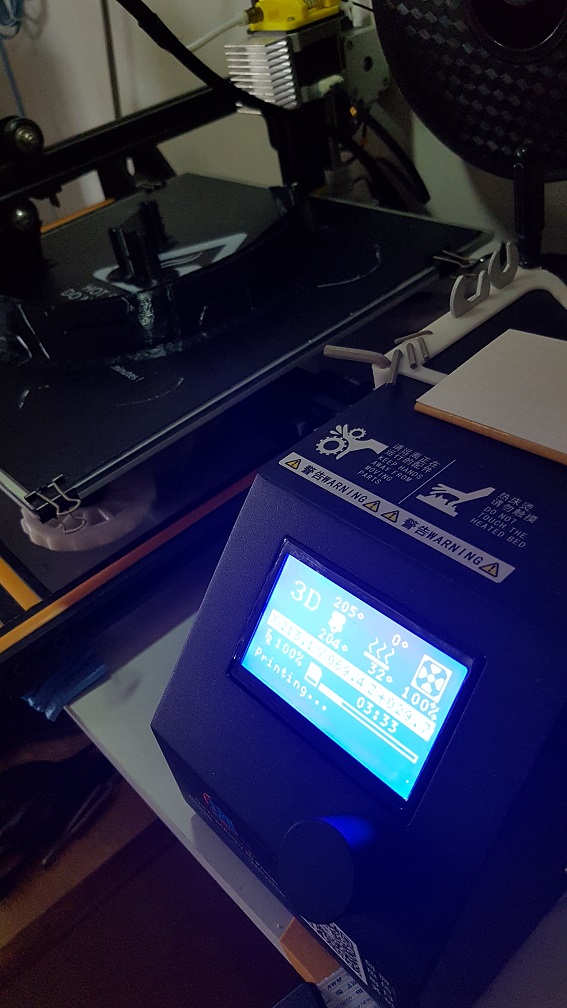
After the modelling which i am really happy with, I proceed to print it.
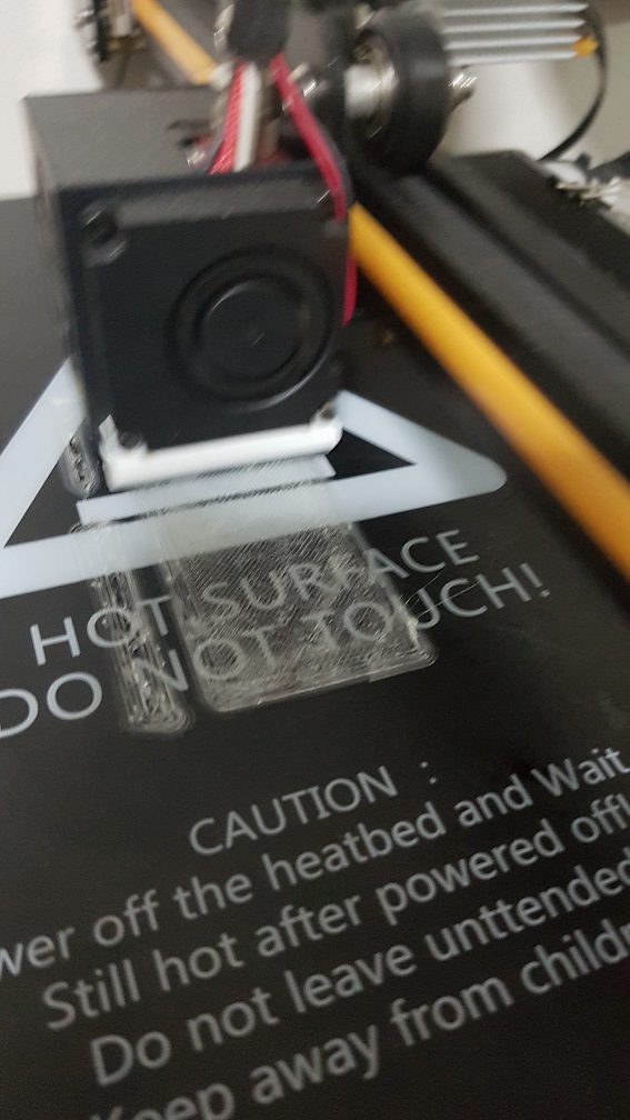
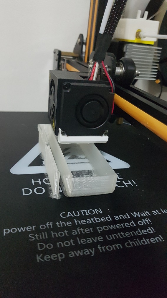
I changed filament to clear filament to print the card slot which was modeled according to the ATM
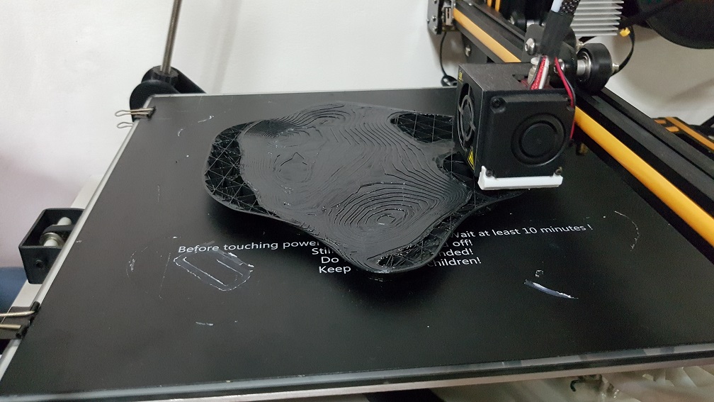
Half way printing, its looking really good
test of size with the music cards.
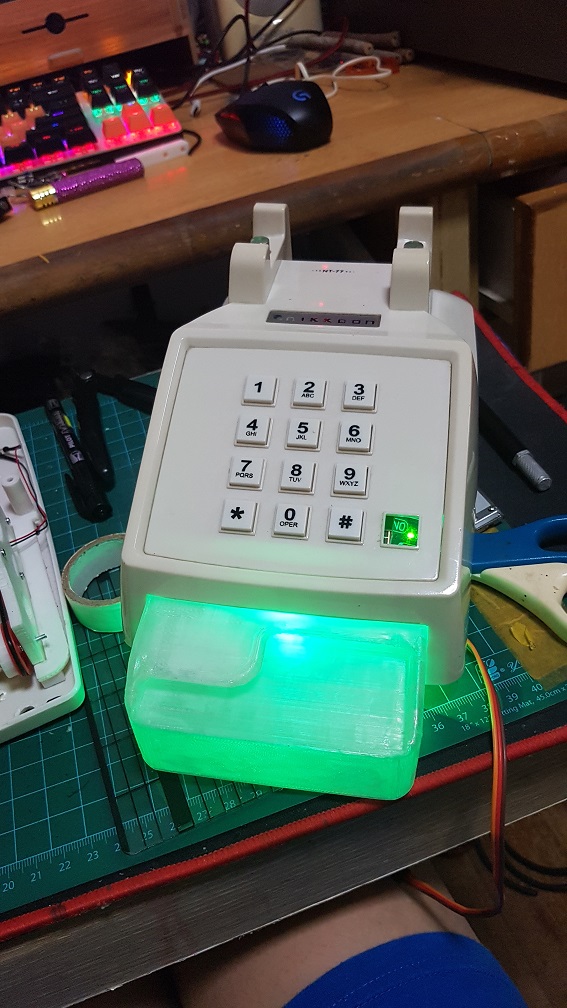
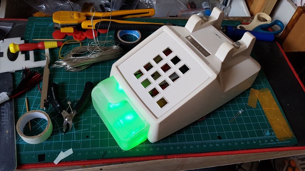
and i tested by plugging in one green LED in it and MANNNNNN IT LOOK SO MUCH NICER THAN I EXPECTED!! I WAS IMPRESSED.
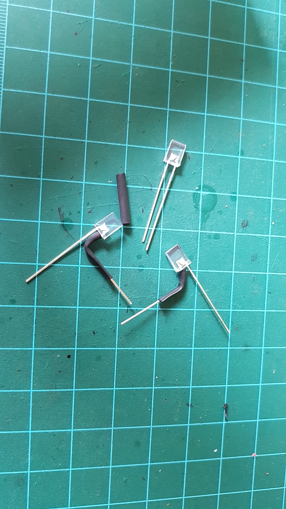
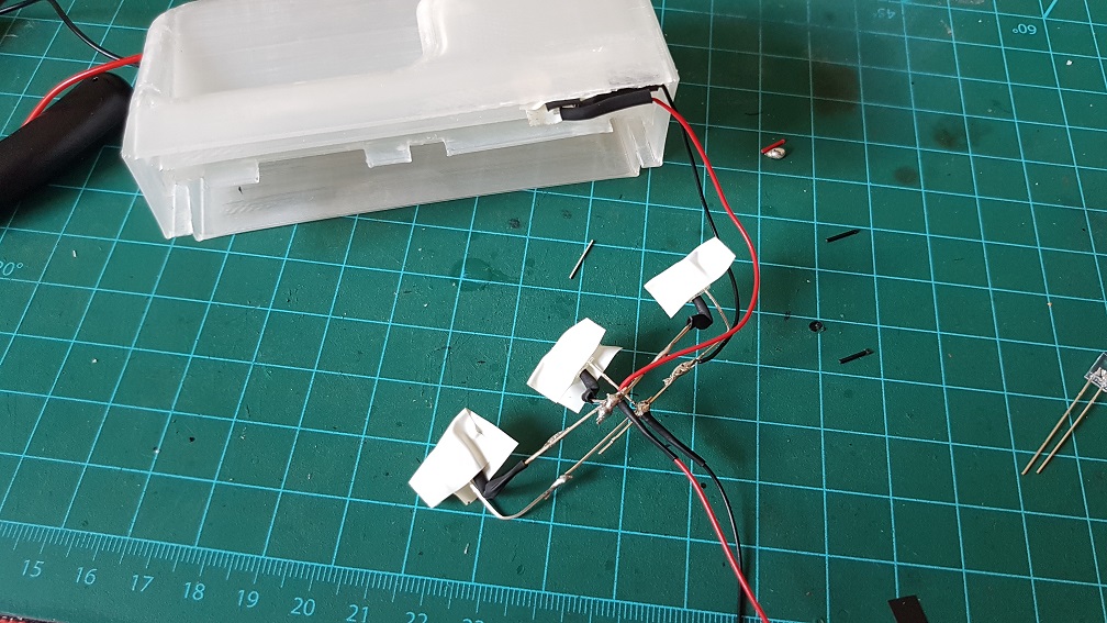
Since it was looking good, I went ahead and make a nicer LED system for it by soldering 4 LED(3 on the bottom and one for the top).
I used the flat and clear when Unlit Green LED so that i could stuck it in the shell on top.
and I soldered the 3 on the bottom and tested it out.
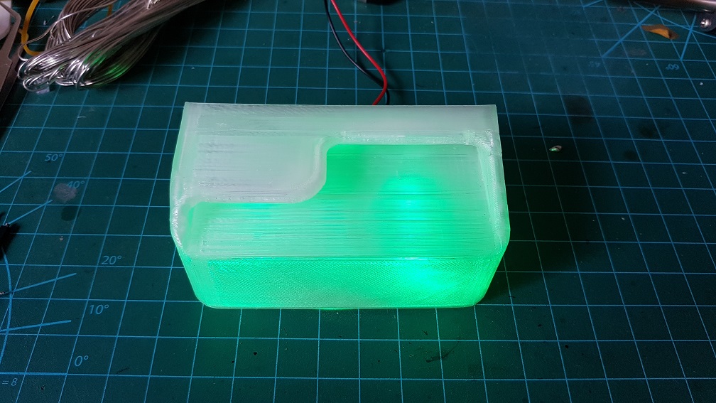
placing it in to see the effect again.
The light was too glaring so I sticked white electrical tape to diffuse the LED to make sure that they glow nicely.
and this is how the system would work.
How the phone should look
Next, I Epoxyed the speaker onto the bottom of the front belt drive since there is already a hole in the bottom shell for the speaker.
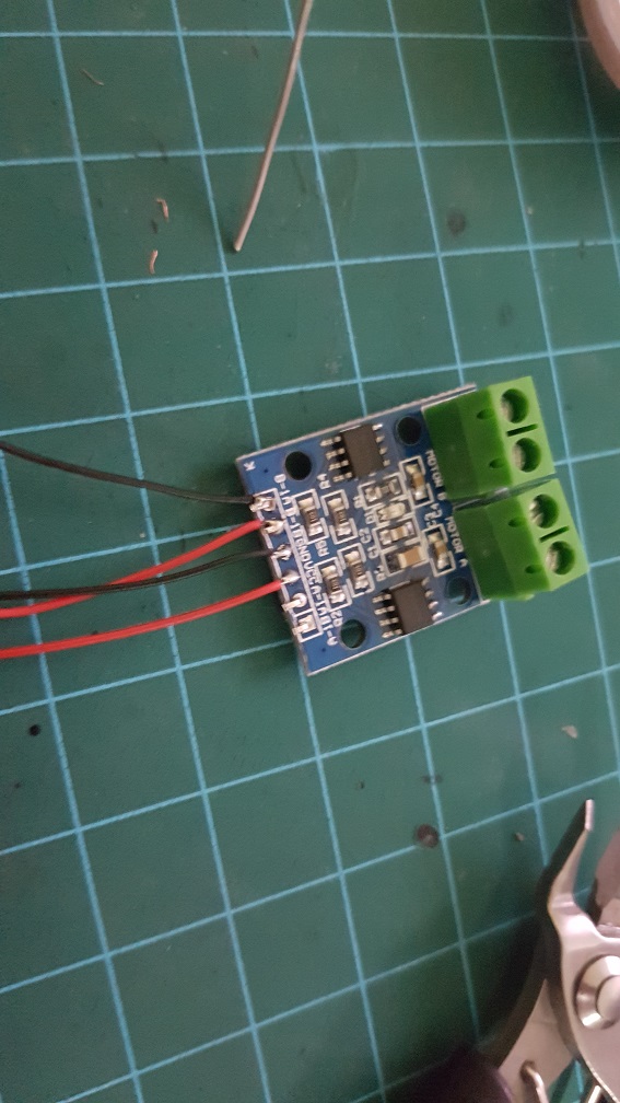
This is the DC motor driver which is used to run the 2 DC motor in the system.
and I soldered the pins too.
I thought I woundn’t need to solder this again… but… i happened to solder this for the 4th times..
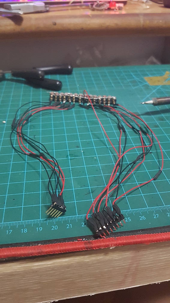
I extended the wires and used thinner and softer wires so aid me in the messy wiring withing the telephone afterwards.
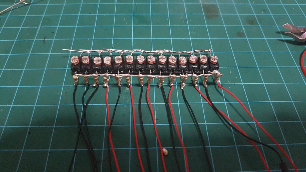
this is the wires for only the photoresistors.
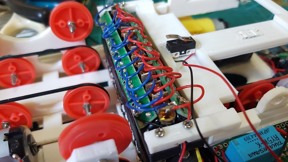
and I soldered the relays which control the 14 laser diodes and the 4 Green LED lights which runs on 2 AA battery to reduce the load on my arduino and to make sure the laser and LED have a stable current flow.
It was at this point then I realized that if i reduce the speed of my DC motor to the speed of the music, I wont have enough torque to pull the card in..
After an afternoon of panicking and finding alternative motor or even thinking to redesigning my whole belt system….
So to solve this problem, I tried to get the medium speed which is faster than what the song should be and will stuck about 30% of the time and removed the buttons (which detects card when user insert into it that trigger the motor to turn the belt.) that caused more friction. And I also jump start the motor by making it to spin at full speed for half a second to break the initial force required when the motor is starting.
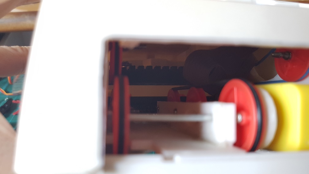
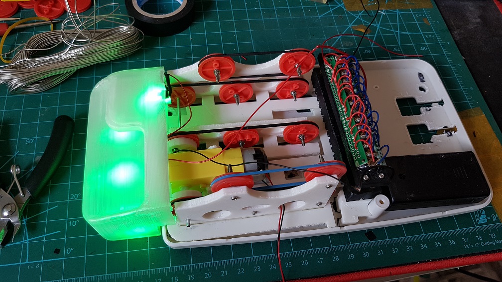
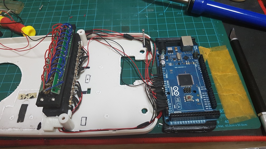
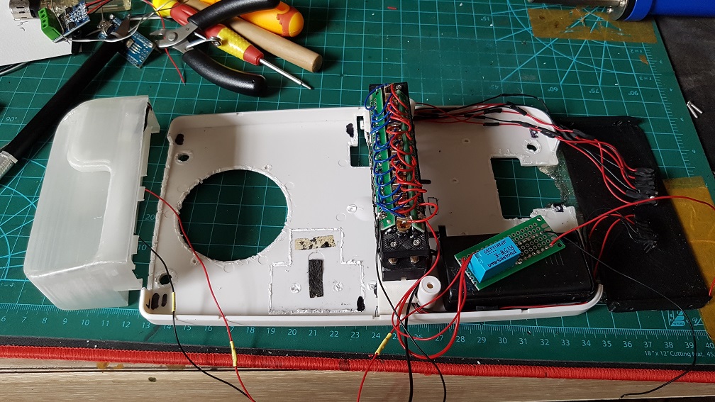
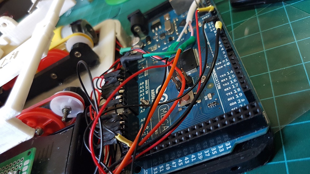
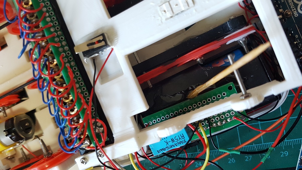
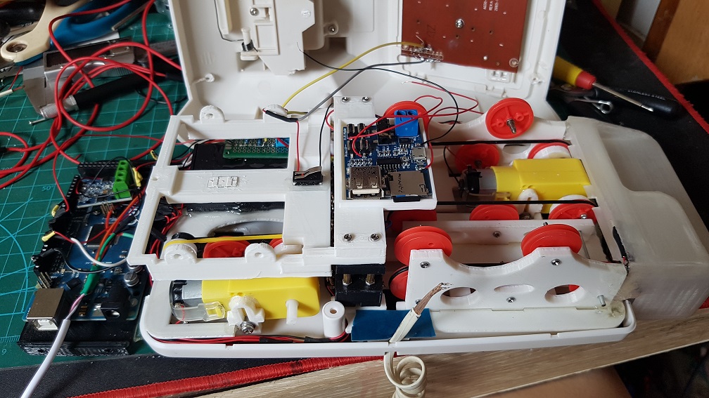
The messy configuration, components and wirings.
It took me some time to sort out these messy wiring and make sure that none of the wires interfere with the track that the Music card is going through.
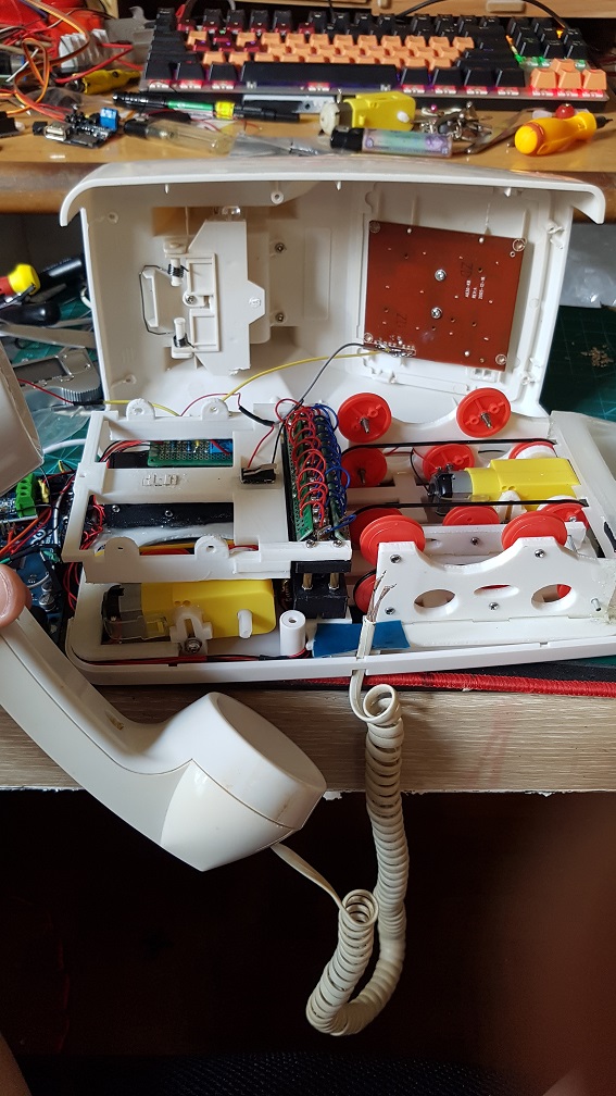
The overall layout before the mp3decoder mount was printed and installed.
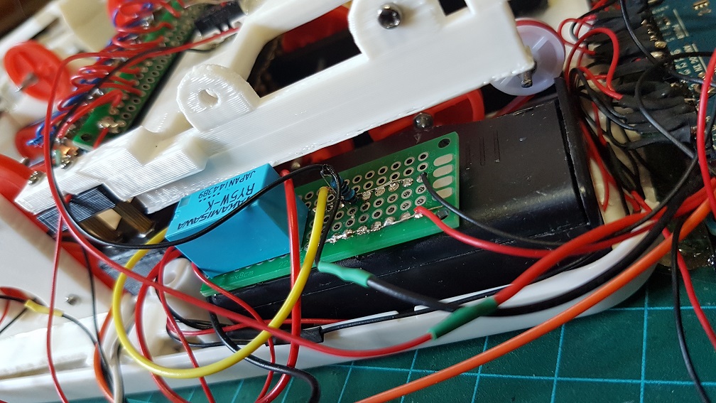
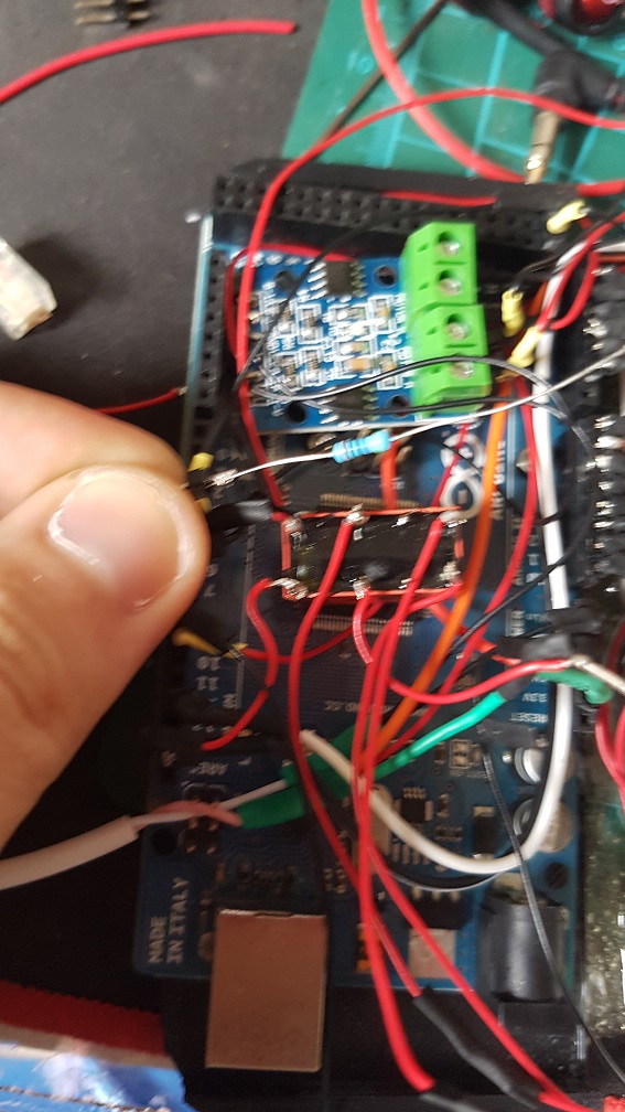
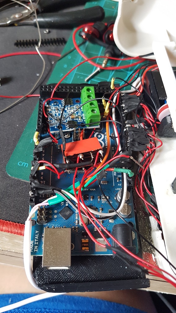
The relay which controls the LED and 14 laser diodes, it work as a ground for other buttons to do the pulldown resistor.
the only part in the whole system that was not soldered was the connection to the Arduino Mega as I intend to reuse it in the future.
Closeup of the 14 Laser Diodes.
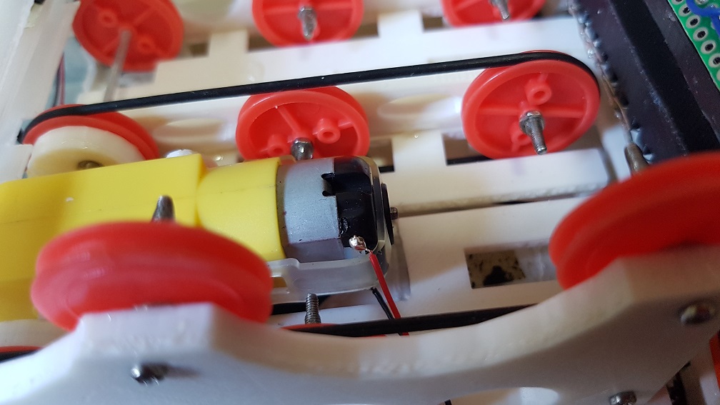
The soldered joint of the DC motor.
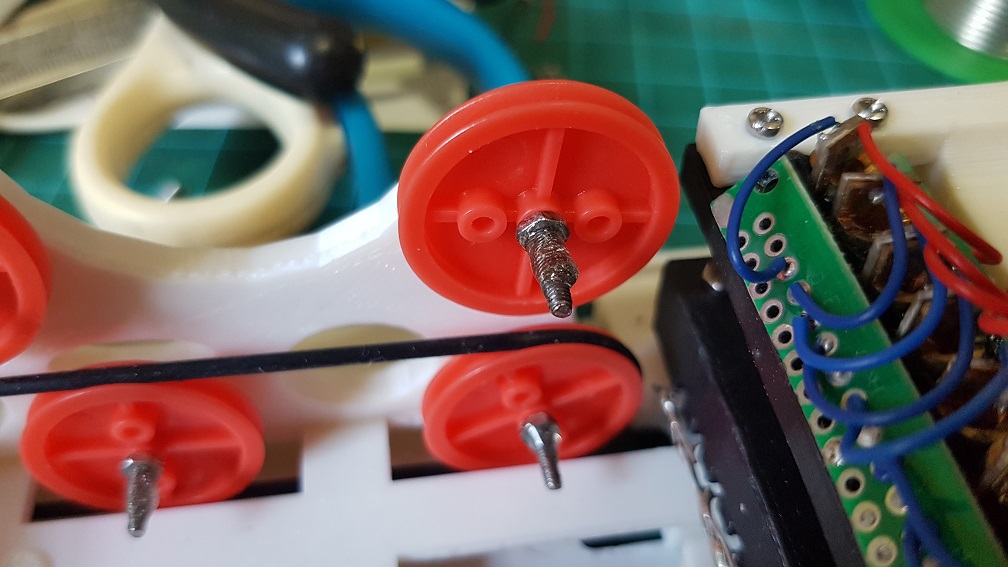
I’ve epoxyed the nuts of all the wheels for the belt drive to make sure they stay where they should be and don’t unscrew/tighten themselves.
I also Epoxyed the relay onto the case of the AA battery to make sure nothing is loose in the case.
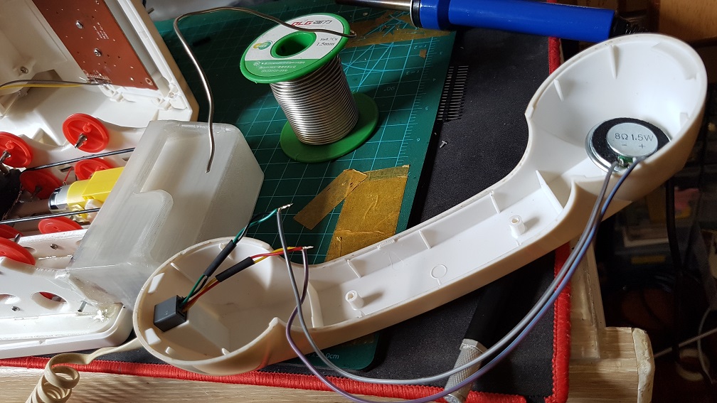
Soldered connection from the phone coil wire to the 8 Ohm 0.5 Watt speaker.
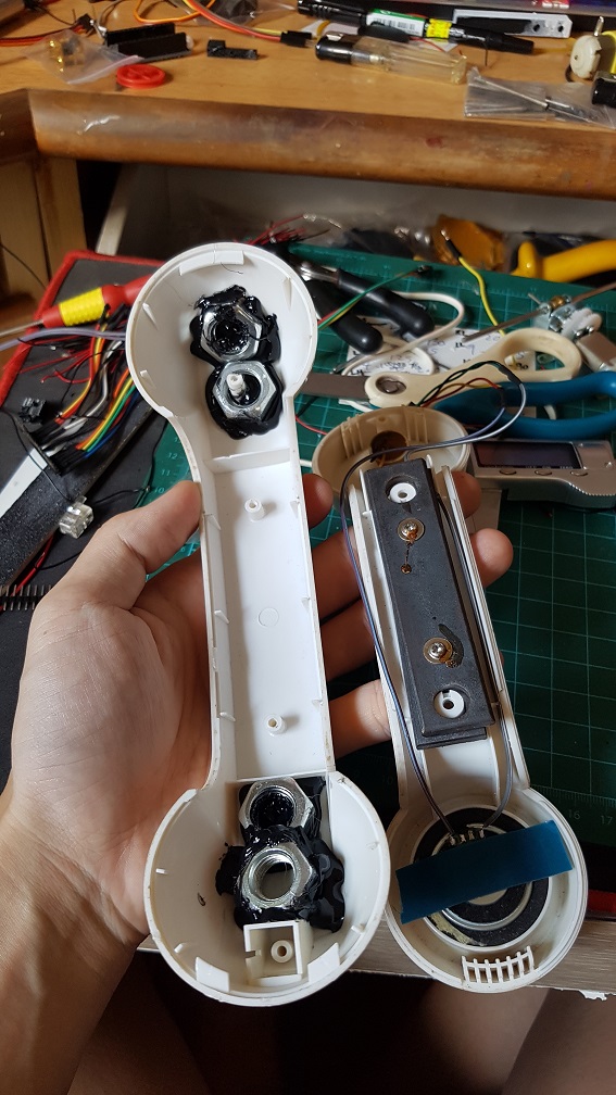
I also Hot-glued four big nuts in the phone to increase it’s weight to make sure that when the phone is in the place, it is heavy enough to press the button down.
the assembled phone
after the MP3decoder mount was modeled and printed, it looks quite good overall!
I used this 400 Ohm resistor to reduce the volume of the tune when playing the music card.
And added a relay that cut the power of the MP3 Decoder since I am not able to control it digitally, the only way was to let it play until it is the start of the next track and cut off the power to stop the voice track. it also switches the circuit of the phone from the MP3 Decoder to the Arduino pin at the same time.
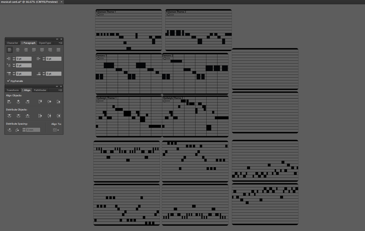
Some may wonder how did I make the Music Card..
I copied a few from online like Demons by Imagine Dragons, Harrypotter’s Hedwig Theme, and Pokemon Theme song, These were labeled on the card and those that weren’t labeled was What I composed myself. Since I have no music background, I did it by trial and error to give it a tune.
This was screen recorded when I tried to compose my 4th tune for this project:
after this was completed, I screen shot it and import into Illustrator to trace it into the Card layout which I made.
AND how about the voice command in 7 different accent?
well, this is relatively simple, just type whatever I want on Webbased Text to speech reader and have it read it out in different accent and edit them in premiere pro to cut them up to the exact same length(9 seconds) and put them into the SD card within the Obseleting Instrument’s MP3 Decoder.
Why did I made it to speak different accent? It was to engage the user and make them feel like there was really life in the system where they called/receive call from a real person, like if they discussed with their friend and their friend said that there was a Indian accent while what they heard was the British accent, they might want to try Obseleting Instrument for a few more time. The accent there is there to add variables in the system.
In Conclusion
Throughout this Project, I’ve learnt many things like how to model objects in Tinkercad and make measurements properly, there are always failures in everything that I modeled before it works, and this is why 3D printing is a good prototype process where I printed it out and tested it to know if it work or not, if it doesnt, I will shave off some piece to see if it fits, if it does, I will make new measurements for the edited model.
Also, to have a Telephone case in the start and scale everything into the Telephone case was really a challenge especially at the start when I could not measure how big the internal was and could only make a guess and print some test print to try it out.
In this project, I realized that if I were to do a project that require multiple fields of knowledge like mechanical and electrical, It was better if I did not know how hard it will be, if I were to know that every part of the project will be something that I don’t know, I will be too afraid to jump into this project. I did something, realized that it doesn’t work and find solution to that single problem and proceed to work on the project and faced another problem, solving and learning one problem at a time lead me to the completion of the project.
Now that I had completed the project and looking back. Obseleting Instrument is really a complicated project as a whole, but thinking about it, I am just putting many small system into one project- like using one laser diode and a photo resistor as a switch, playing a tune when triggered, a physical button to sense if the phone was picked up, using a relay to control circuits of different voltage, running two DC motor at the same time and so on… Obseleting Instrument is just a collection of small systems, which I personally thinks was what made my journey of doing this project really interesting because I explored the basics of these components and learnt a whole lot through it.
Continue from my part 4 of this project updates, This is the final part which leads to the completion and is rather long as many things from getting the power supply, modelling, testing, painting, assembling to coding had been done in the past 2 weeks.
First, the final video of The Curious & Timid Turtle.
And then, into the process….
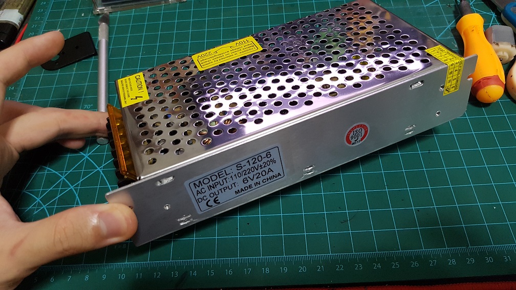
NEW POWER SUPPLY!!!
At the end of last post, I was waiting for the power supply to reach and it did during these 2 weeks so I’ve tested it out, The one that I bought is a AC-DC converter at 6V 20A when all I needed was 6V 8A, i decided to buy the higher Amp one just if i need more amp in the future, and I could also share the supply to my Interactive device project during the End of sem show.I did some wiring afterwards.
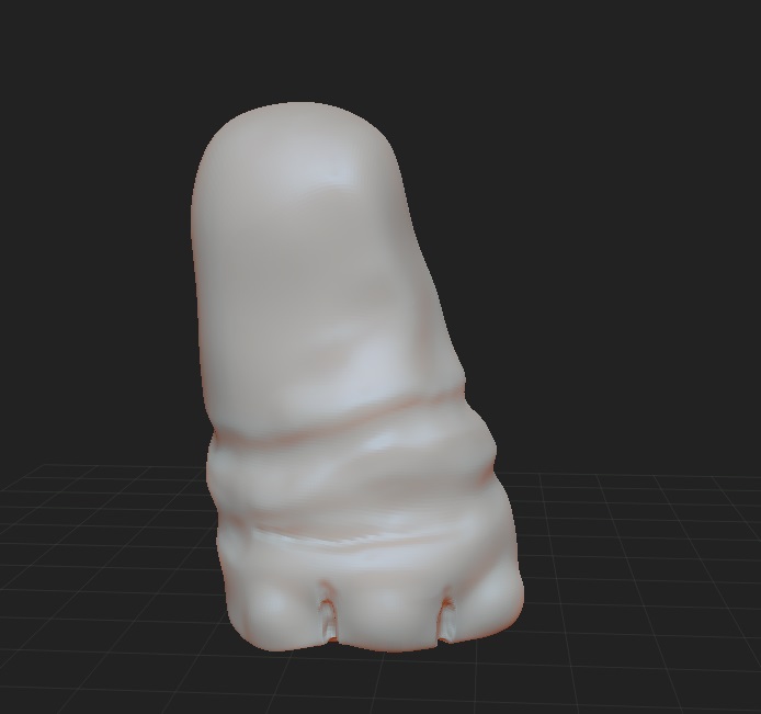
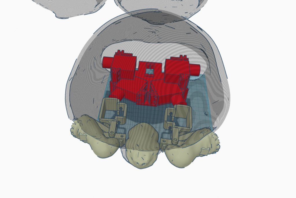
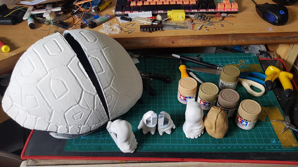
Since the last post that I’ve decided to change the system in the legs to save space and shorten the overall length by stacking a smaller MG90S on the MG966R to act as a lever system to pull control the legs. After testing this system out and seemed to be working, I merged it with the turtle leg that I’ve modeled in Zbrush, I don’t know about Zbrush before this project and it tool a long time just to model the shell, the legs and the feet.
Backleg model
Backleg model before final
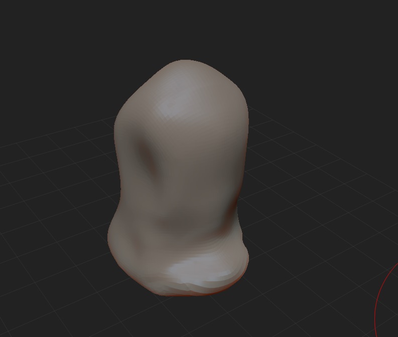
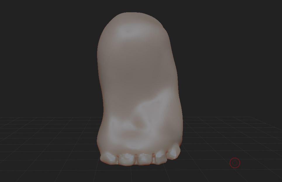
Frontleg model
Frontleg model before final.
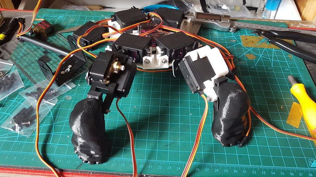
I merged the leg with the previous test “rod-like” leg because I’ve already gotten the dimension in there so i just need to scale the Zbrush modeled leg accordingly to fit the “rod-like” leg.
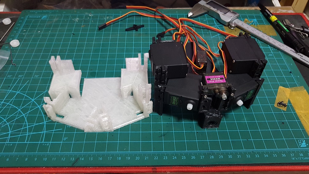
changing of the entire base layout to reduce size and increase EFFICIENCY for the back legs.
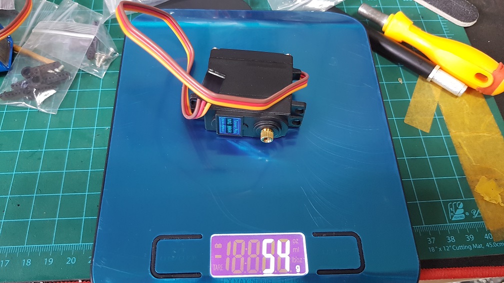
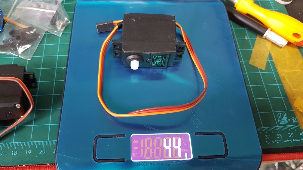
At this point, I was wondering if I should change the MG966R(metal gears) into SG-5010(plastic gears) due to weight issue I might face later after adding the shell and so on, so I weigh the motors and decided that I should change the back leg to SG5010(but I changed it back to MG966R one day before submission due to the internal gears got loose in SG5010)
MG966R is 54g
SG5010 is 44g, the difference is 10g so by switching 2 motor, I could save 20g of weight in my system. and so I did.
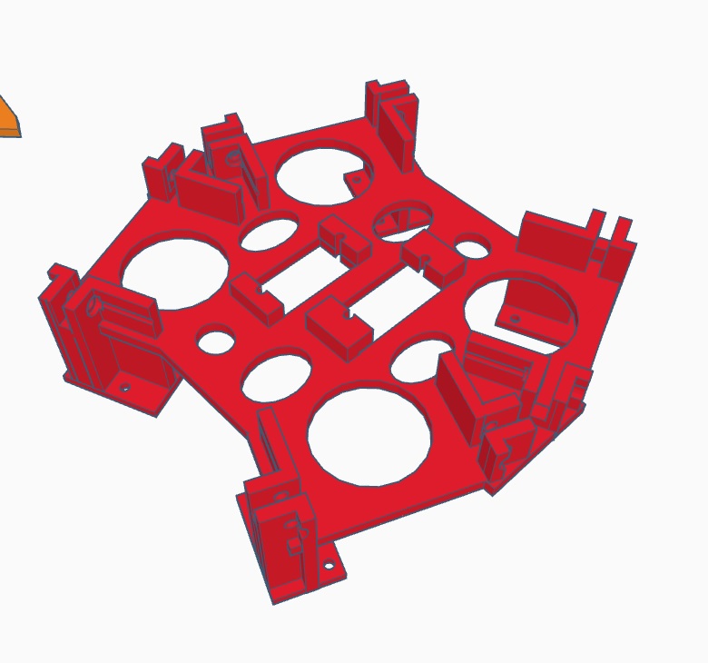
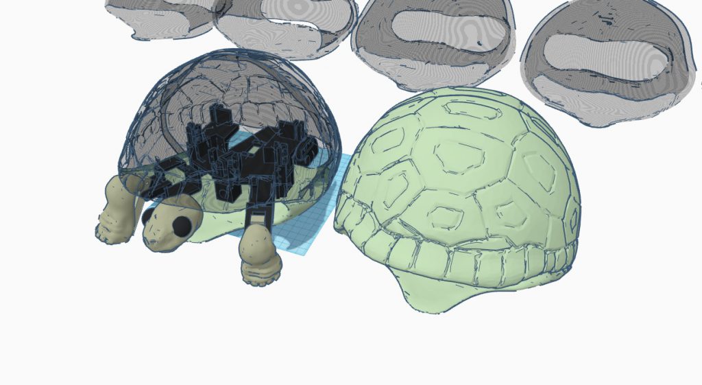
Major changes were made for whole layout of the base due to various reasons – the backleg will move differently from the front and since my project is basically a turtle with round shell instead of a flat one, it made more sense to use a smaller but higher layout rather than a flatter and wider one to make use of all the space within the shell.
This was the previous layout(Version 4) which made the whole shell really flat and big
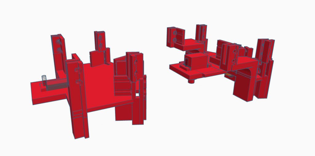
and this is Version 5(left) and Version 6(right) which I stacked the servo for the back leg on the shoulder servo of the front leg.
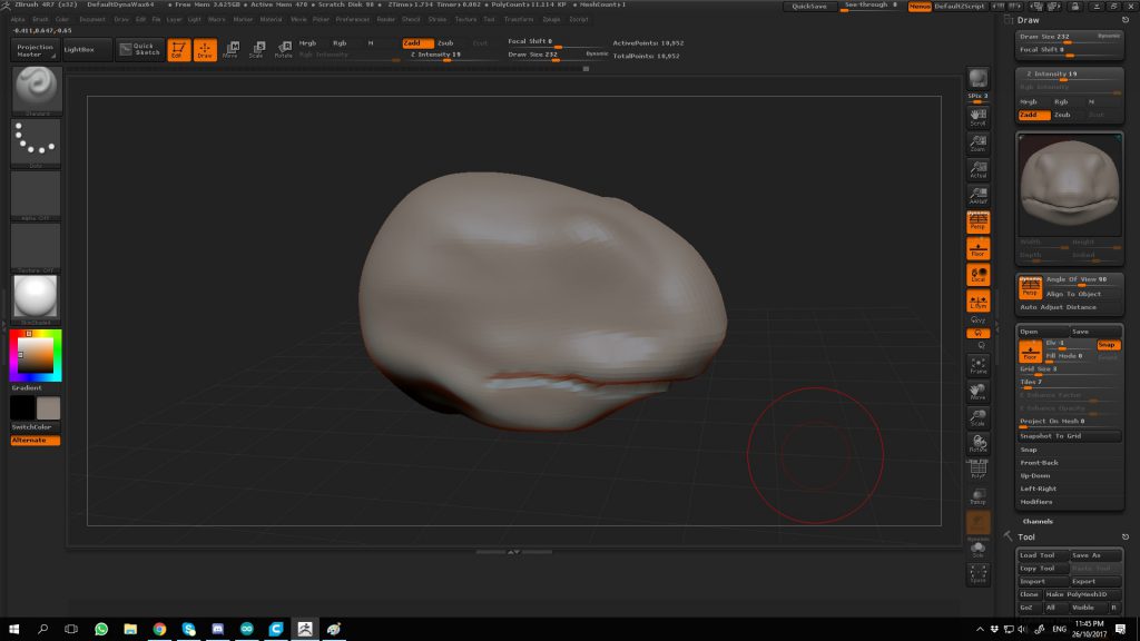
Since my Zbrush was cracked, it crash rather often and I did the same thing over and over if I forgot to save frequently and hence it took quite long to model anything, but well~~
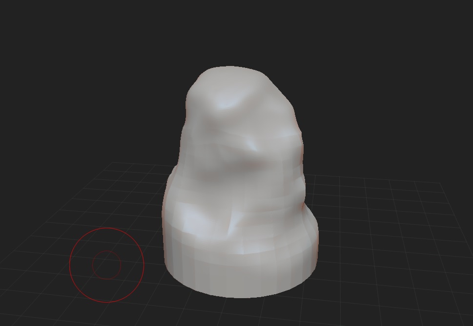
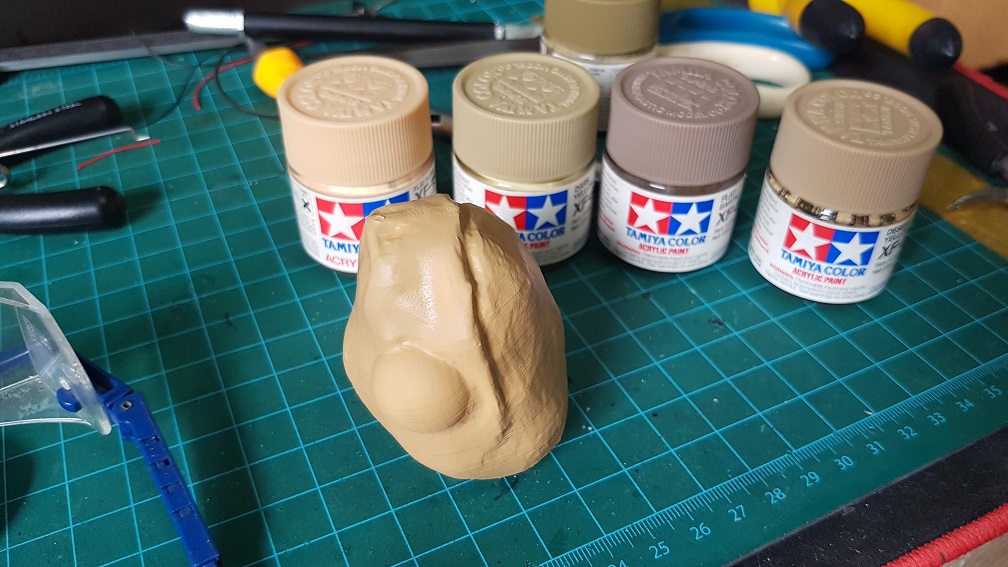
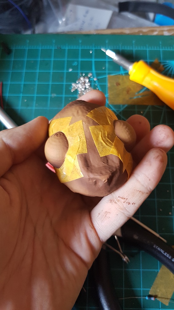
The head started off as a sphere
and tried to model it as close as the turtle head as possible.
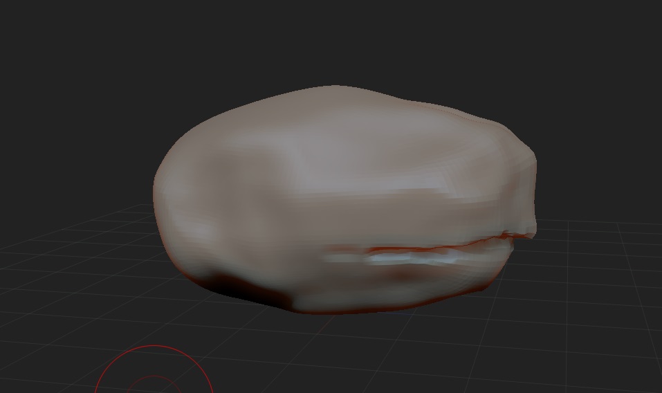
and some general shape edit
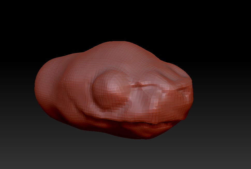
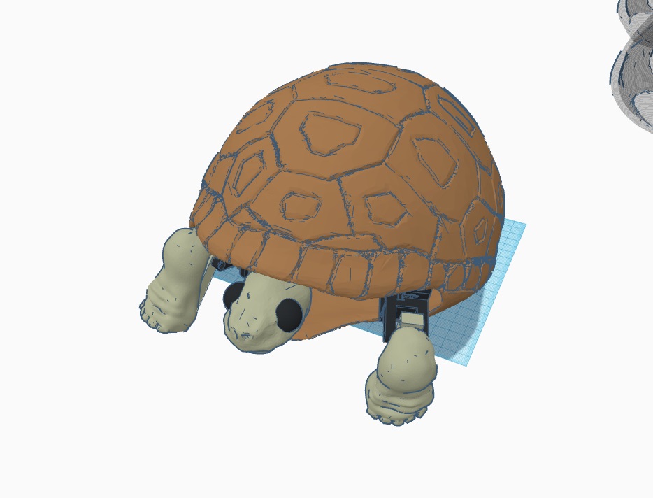
slowly, I edited it to look like a reptilian head, and instead of getting the real look of the eye, I’ve decided to enlarge the eye to give my turtle a cute look (and because the eyelid looks too hard to model).,
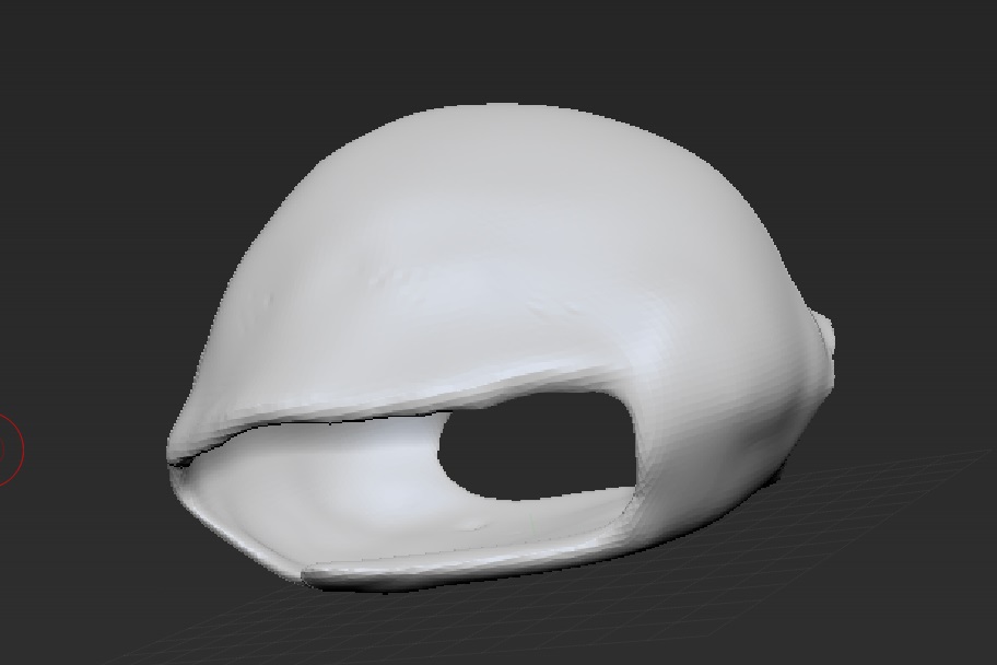
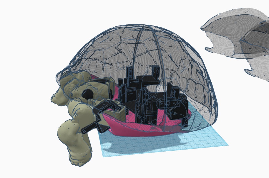
As for the shell… it took so much time and crashes to get it right, because the shell cannot be too thin(unable to print later) and cant be too thick (too heavy) and I cant find a function that could allow me to see the thickness (like reduce opacity of the material to see through), so everytime to check the thickness, I have to export into STL, and import into Tinkercad to check the thickness.
This is like the version 11 of the shell.
I used this image as the sample for my shell pattern
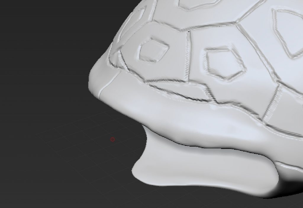
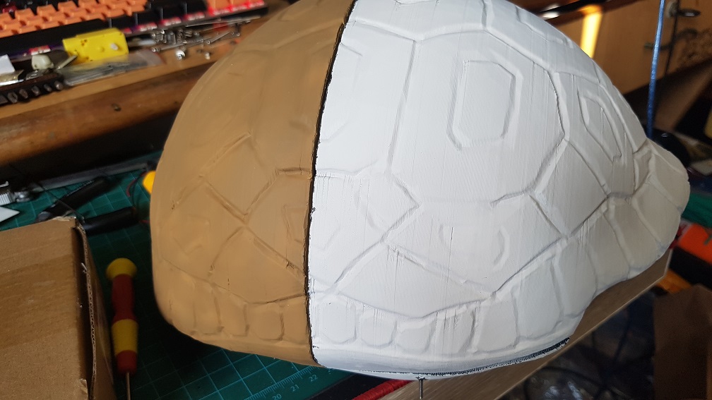
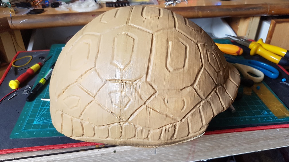
topview when I marked the turtle pattern onto the shell
and i further carve the pattern out.
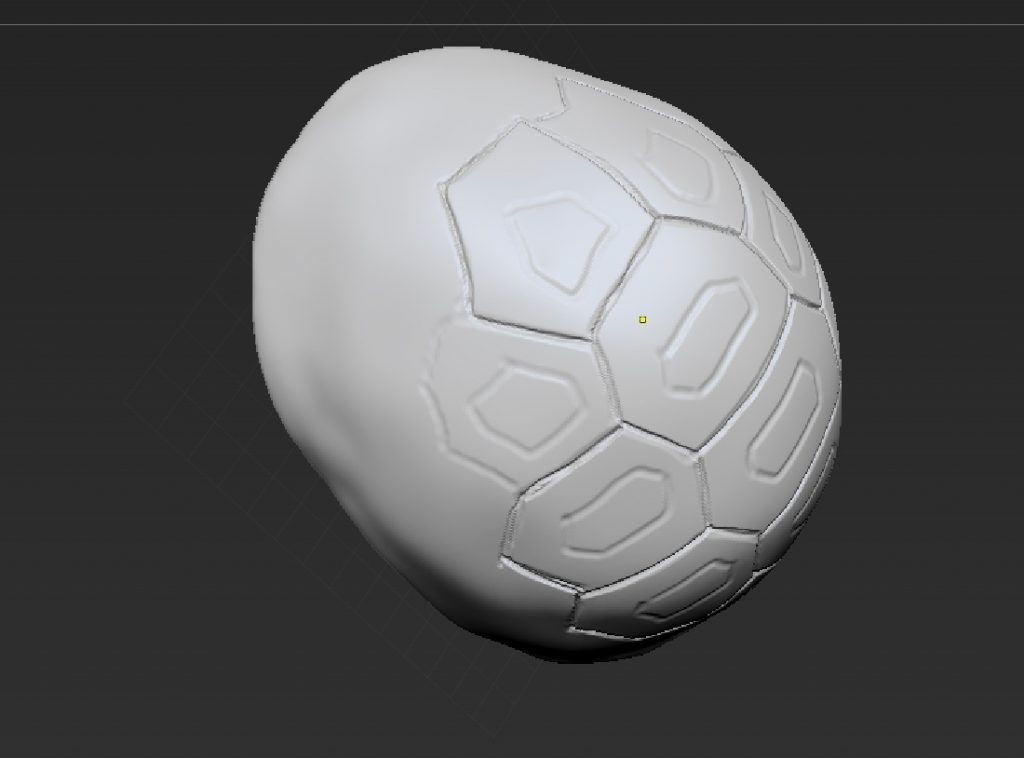
the rim of the shell i did without any reference and I marked it out
and carved into it.
Everytime I made major changes to the shell, I’ll have to import to Tinkercad to check the thickness and shape.
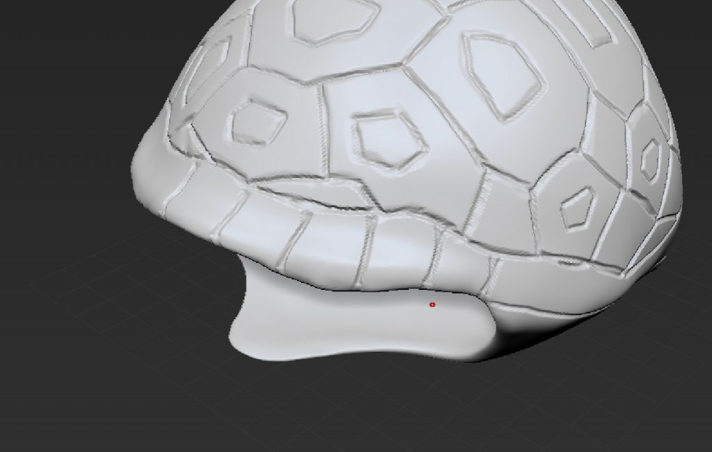
this was almost the final shell before splitting the shell for printing.
I split the shell top(transparent) and bottom(Pink) in Zbrush because its following the shape of the pattern of the shell, and the top half into 2 in Tinkercad as a straight cut will ease my printing later. I also added 4 holes that allow me to reassemble them using bolt and nuts later.
The comparison of V4 base with V6 base. V6 is much shorter at 150% higher,
The white one was Version5 which was a test print that I realized that the motor is unable to be fitted into it so I cut some material off and remeasured.
the front of the base is a liner bearing that i could slide the rod for the head.
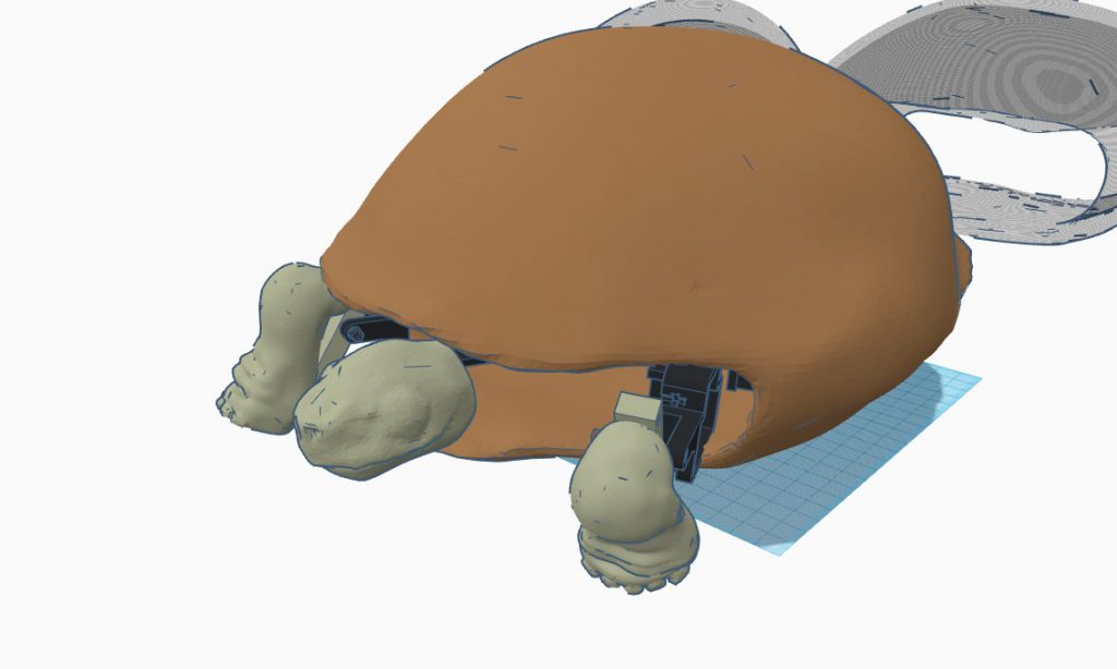
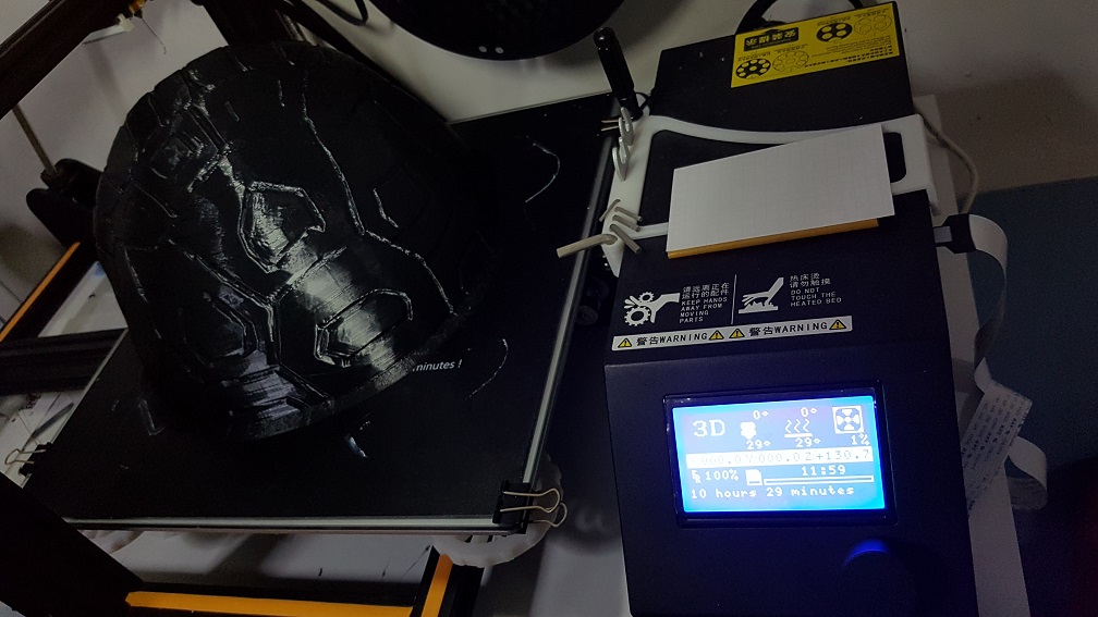
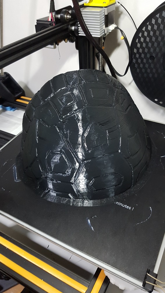
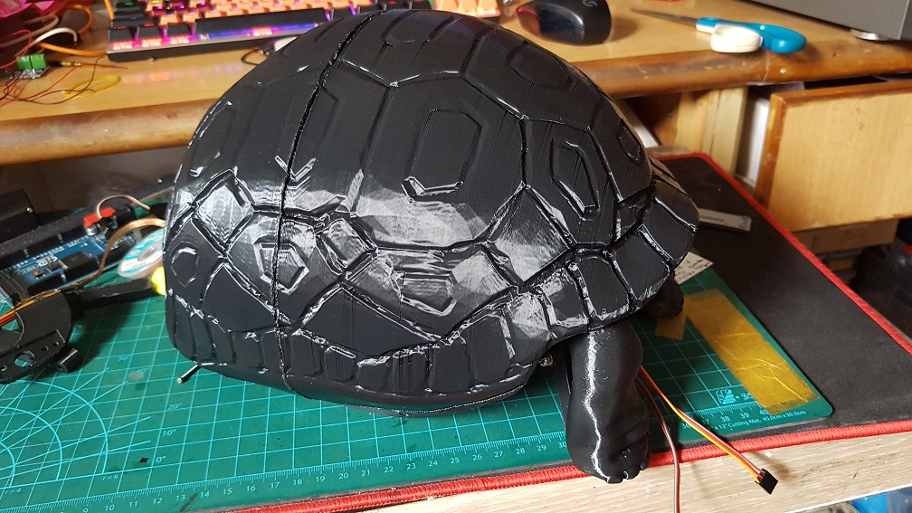
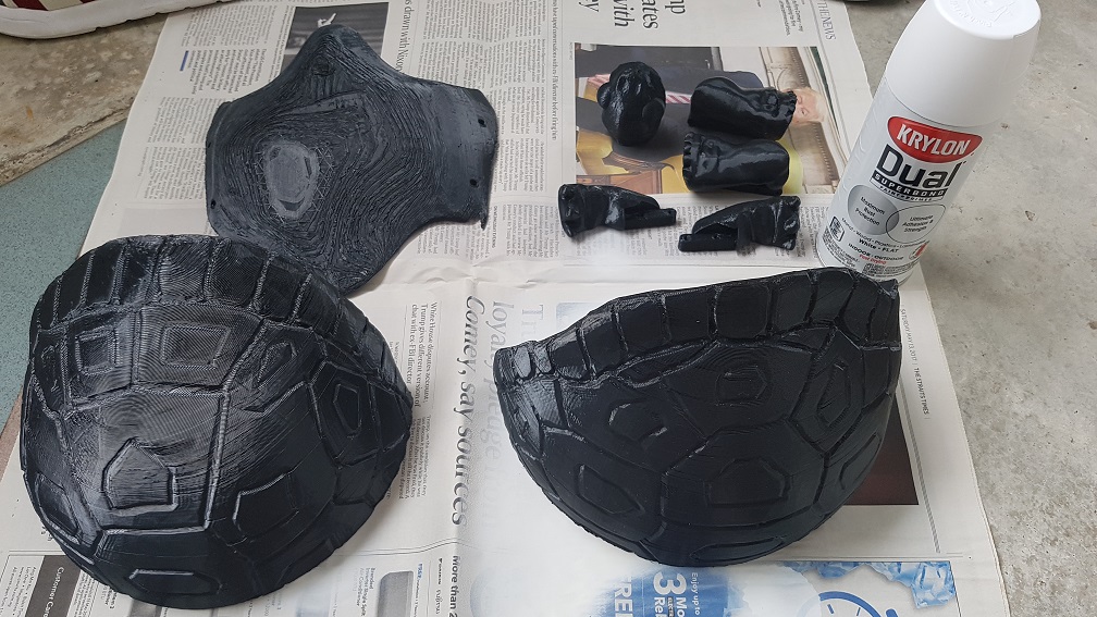
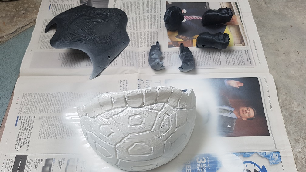
I sprayed the overall colour of the turtle with Tamiya Acrylic paint.
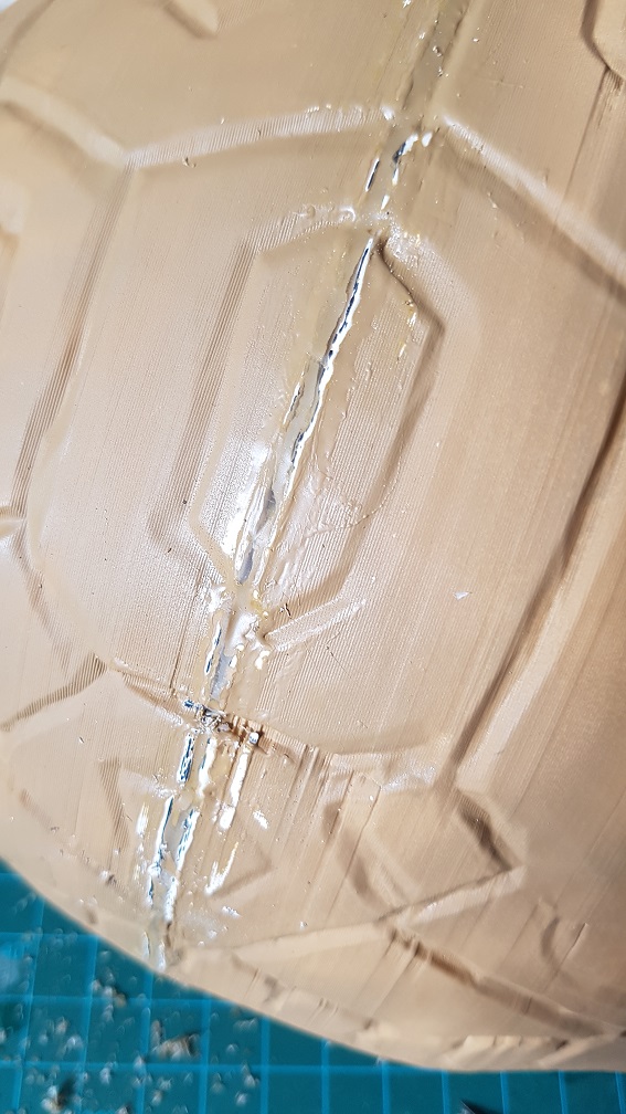
halfway through the spraying, I remembered that I need to epoxy the two pieces of the shell together first.
and so I epoxy it 3 times and sand off the extra epoxy to hide the glue line by a bit.
although it is still visible, I think it is a reasonable standard since I will be painting it further with darker color afterwards which will hide the glue line more.
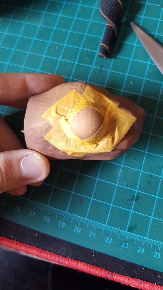
and i masked the eye using tape for me to spray it black and glossy
and i carefully cut out the tape in the shape of the eye.
After this, I added a few lines of code to substitute the button pressed with sound sensor to make the turtle more intractable and a few more actions that made it more timid looking (head peeking out to check the environment before the whole body come out.)
In conclusion:
Overall, I really liked this project although I kind of regretted trying to make a turtle during the process because the shell is giving a lot of layout and movability problem made me kept thinking that if I were to make something without shell, it will be so much easier, but the reason that I first wanted to make a turtle is the best is because the shell naturally hide all components that break the user’s perception that this is a robot and a turtle is my spiritual animal, now that I finished the project, I am really glad that I sticked to my initial idea of making a turtle and persevere through all the problems I faced(mainly hardware and mechanical problems which I changed my system and design so many times.).
With more time, I am sure that I could code the turtle be able to be scare back into the shell by another sudden loud noise – I tried to change the delay in my code to Millis multiple times and it do every action in the sequence twice so I sticked to using delay for now, which disabled me to write the activation code for using the sound as a trigger since it is in a delay loop. But, it looked really nice for now even if there is only one sequence of movement and I am glad that people were thinking that the turtle is cute when they saw it.
First of all, we did not want to use the Facebook Co-Broadcasting function as our goal of this Telematic Stroll is to test out the system for our final project(there will be four broadcasting at the same time and none of us could see what others are doing, yet we will form a piece together.) ANNDD MANNNNNNN~~ THIS WORKS SOO MUCH BETTER THAN EXPECTED!!
This was the Broadcast which I did and viewing it individually doesn’t seemed like much, its just a random walk-around video which wasn’t impressive at all.
But when linked it with Bao’s Broadcast… Things get a little more interesting.
Both Broadcast were not edited in any way except for putting them side by side, if we create a video wall and play it directly, it will be the exact thing.
The video were done on the spot through Facebook Live without any feedback of the other Broadcaster available to both of us, we only know what we were doing while unable to see the other party, even if we do, there will be a 7 second delay between broadcasting and watching live.
In conclusion, This is Magic.
But how are we doing it? It’s a secret for now and we shall keep it until our final project. For now we are still improving our system and you should just take it as it is a MAGIC. TADAA!! A sense of wonder for a viewer is what we wanted to achieve.
This is our one and only try. Most of the times we were uncoordinated and we did not discussed what to film beforehand while there were mistakes made everywhere throughout the broadcast and we did some of the mistakes at the same time which made it seemed intentional, making it even more magical.
To point out some of the wonderful MAGIC we did.
We did not know where the other broadcaster were in and neither do we know what we will be filming, except for our leg, our face and the sunrise, and we started by going through a bridge AT THE SAME TIME
Also, we managed to synchronize our steps for a rather long time.
We switched the camera to film our face at about the same time.
I really liked this part of the broadcasting, Since the only thing we planned on was to film the sunrise and still I managed to screw it up by filming the wrong direction for about 3 minute then realized that the sun rise from the opposite side. MANNN I WAS WRONGGGGG THE SUN RISE FROM THE TOTALLY OPPOSITE SIDE…. I SCREWED UP BA.. OH HELLO SQUIRREL! OH I STILL SCREWED UP.
The matching of landscape and the tree was totally unintentional and it turned out really beautiful. one was like having the orangy clouds really near and one was REALLLLYYY far. which is amazing
And the switching of camera was so good in this one too!
In this Telematic stroll, we had found out what problem there is during the live broadcasting and will improve it for the final project, also, it had been a really long time since I woke up this early.
we checked the timing for sunrise and it stated that it was 6.47a.m, but the actual sun came up only around 7a.m which is when we finished our Telematic stroll.
Finally, I am REALLY impressed when I put the video next to each other, they worked really well and there is improvements that could be made and we all learnt from it.
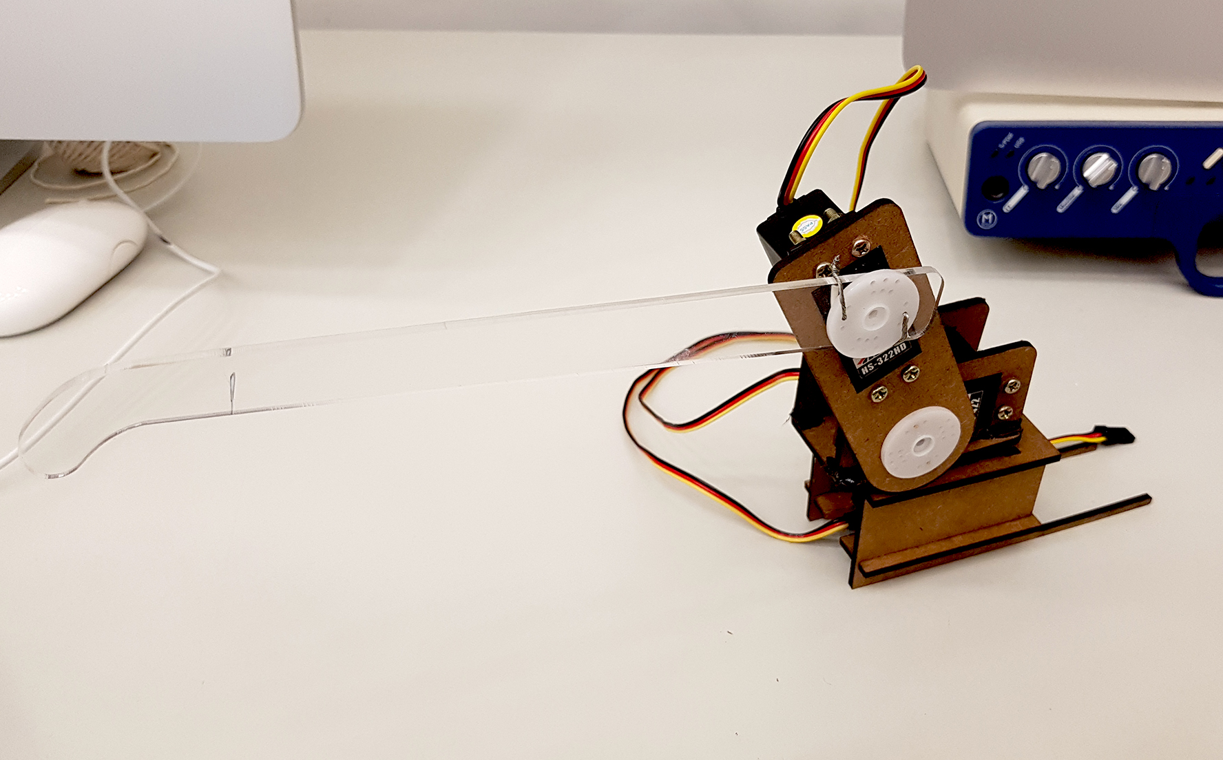
This was a great project for us to learn about how to program a servo to move, basically for this project, we had some failure as but the end result works far better than what we expected. Our first laser cut was was too long and we re-cut them together with the rest of the parts.
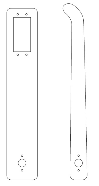
And then came our Ver1 Typebot that is almost made from MDF with the finger that we knew it was too long(the marking was the length we needed)
the base of the rotation serco were too big and “wrist” were too short so we couldn’t get it to revolve 180 degree due to the size error and we went into making the Version 2.
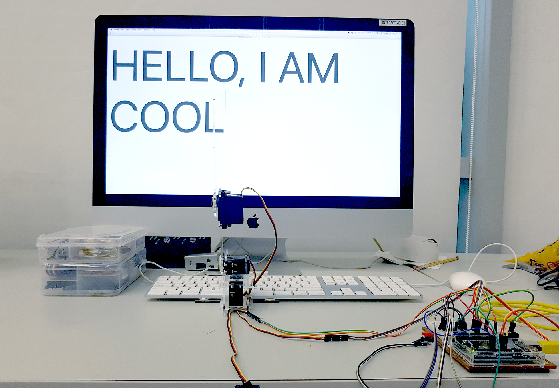
This was made into our final Typebot as the length were just nice to press the nearest(Spacebar) and the furthest button (Escape), which was what we needed as we wanted to make the Typebot to possibly type all the letters.
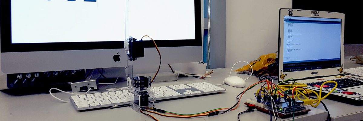
The base of the Typebot was sticky tacked to the base of the keyboard to fix make sure that it will not shift around from the time I calibrate each letter in the Arduino IDE to the completion of this project.
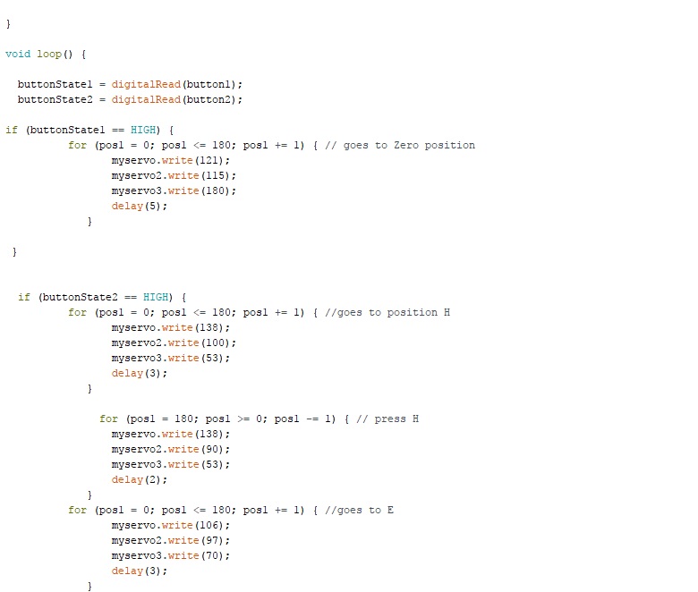
Basically our Arduino code consist of 2 “if” function which are triggered by 2 button. Button 1 will reset all the servo to the original position as we found out that when uploading the code to Arduino, servo 2 will goes all the way to 180, so to prevent it from pushing all our parts to breakage, we will reset the position before uploading so the maximum it will move is to only touch the table hence all our parts will be safe.
Button 2 will activate the code and help me in getting the values for each motor by allowing be to repeat the movement just by clicking the Button2. For the Typebot to press one letter, there will be 6 values for a smooth movement from a letter to the next – 3 values for Servo1,2,3 to travel to the position above the letter without dragging over other keys and 3 values for Servo1,2,3 to press the letter.
The rest will be just trail and error to get the values for all those letters.
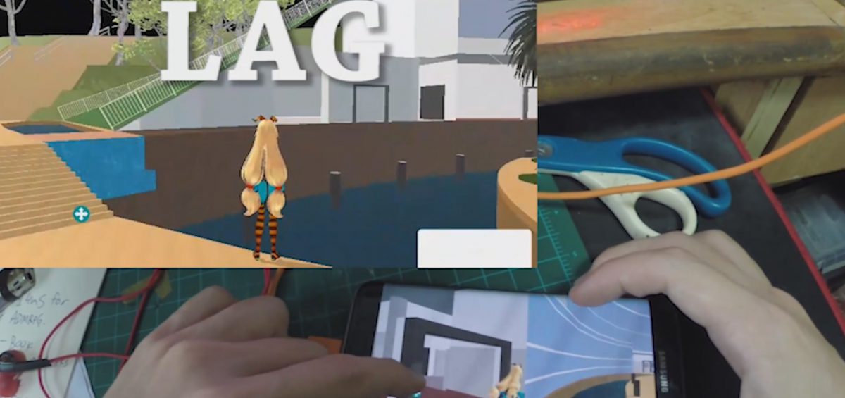
Exporting to phone is not an easy process as I need to download many different softwares like JDK (Java Development Kit) to make it work, I am not sure how does it even work when it failed countless of times, I also switched my phone into developer mode and somehow the app appeared in my phone when I’ve export it to my computer. Most of the thing I’ve followed this video, and i just try again after it fail.
This is what I have after the export, It is basically too lag to be played properly and the experience of the game if it lag is not worth the time playing it and It will be rage inducing if it is at this level of lagness.
After this, i decided to scrape the idea of making a phone game and focus on computer platform as computer have much higher processing and rendering power.
This was the hardest Max patch we wrote up till now as it is logic base and after LPD taught us about the function of different commands –
Clocker(used in the patch to count down the 3,2,1,)
Timer
Speedlim (use in this patch to prevent sound from looping endlessly)
Pipe
Select
Split (used in this patch to split zeros with all other number hence when there is no value = 0 = do nothing)
Route
Trigger
Gate (I tried to use this, but diden fully understand this so i used IF statement)
Onebang(my favourite) (make sure there is only one bang until it is reset)
Counter
Line
LoadBang
Loadmess
Scale
Expr (to put mathemathical expression (x1 + x2)/2 )
Pack and Pak
all of these are basic tools and if one can use them to their fullest by chaining up different object, alot of cool stuffs could be done in just these objects.
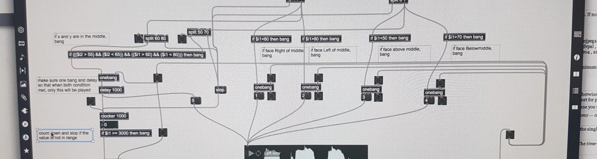
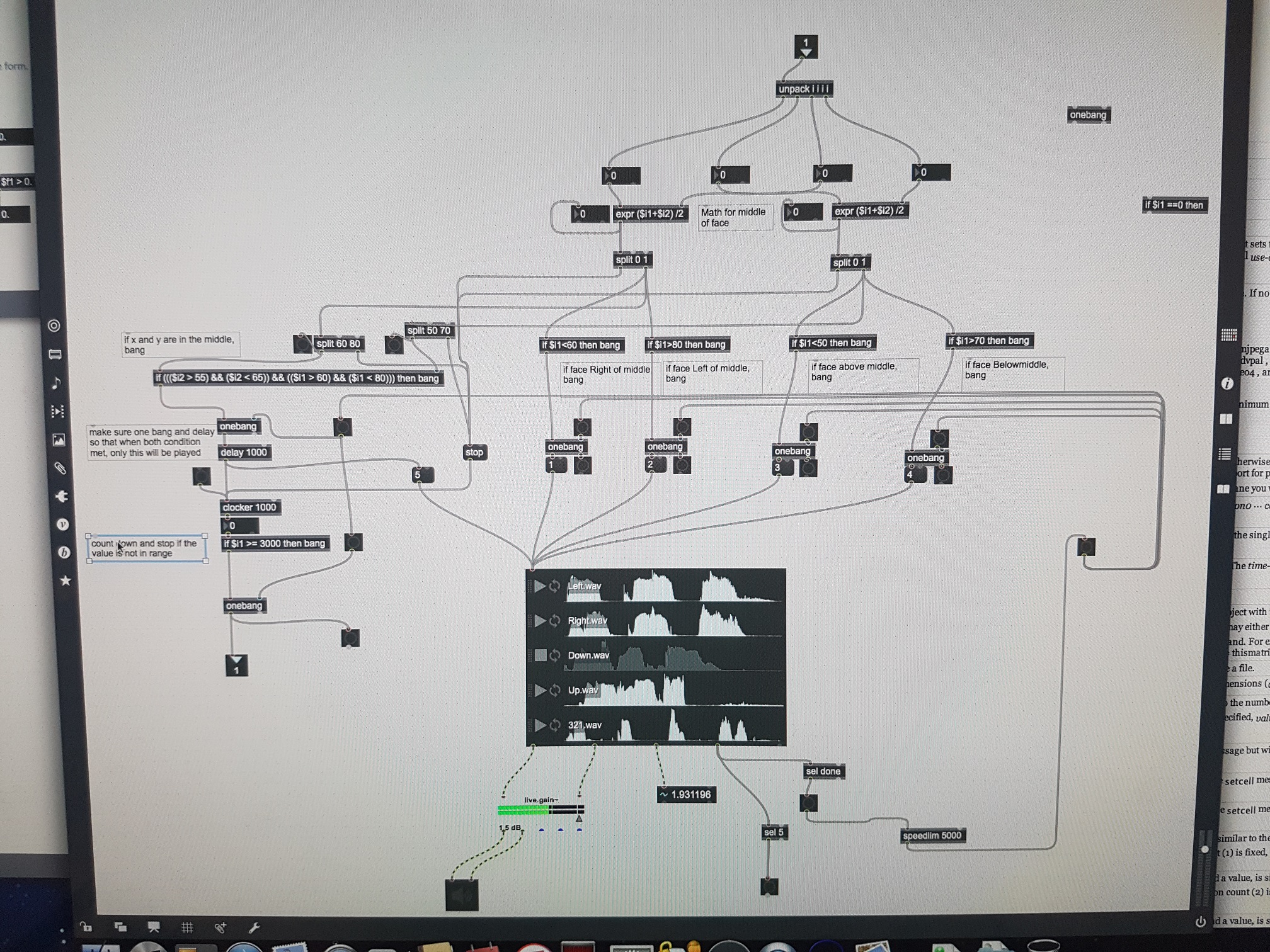
This is the main piece of patcher in my patch, the rest of the patch are very similar to the previous exercise, so in summary, the flow of this patcher
get the square value from face & unpack it
find the middle of the square in terms of X value and Y value
split into 5 zone
1) Middle Zone (MZ) (the zone where X and y value are around the center, for my patch it is 60 < X < 80 and 50 < Y < 70),
2) X higher than MZ
3) X Lower than MZ
4) Y Higher than MZ
5) Y Lower than MZ
For 2 to 5, send the number straight to the audio player
And for 1,send the number to audio player while if the value stays in the zone without X or Y going out of the zone for 3 seconds(using counter and if $i1 >= 3000), then take a photo, else stop the timer(and when the timer resumed, it will auto start from 0
lastly, I used a single playlist of audio player just because i dont want the patch to play more than one sound clip at any given moment, the only way for different soundclip to play is either
1) when one clip finish playing and the condition is still the same, it will playback the same soundclip after 2000ms or
2) when condition changed when a soundclip is playing, it will then stop the current playing soundclip and play another sound clip instantly.
I hope this is relative clear of the flow, through this exercise, I learnt mainly about logic flow, which i think is the most important in every kind of coding.

 This is a 8 Ohm 0.5watt speaker that will be plugged directly into the Arduino.
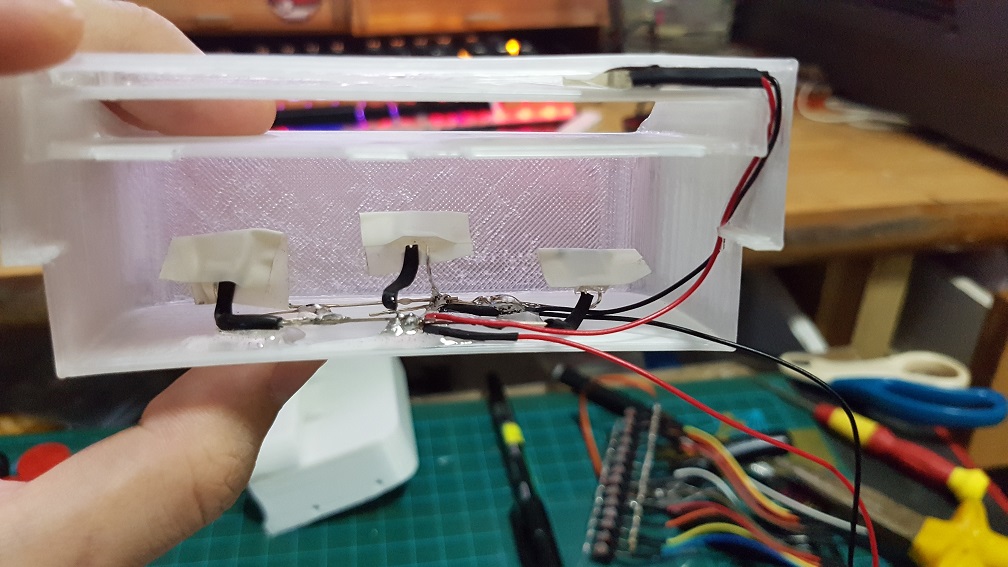 I also Epoxyed the 4 LED into the card slot to prevent them from sliding around.
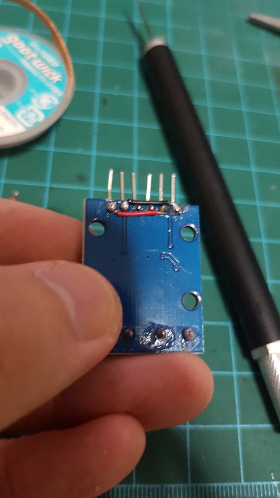
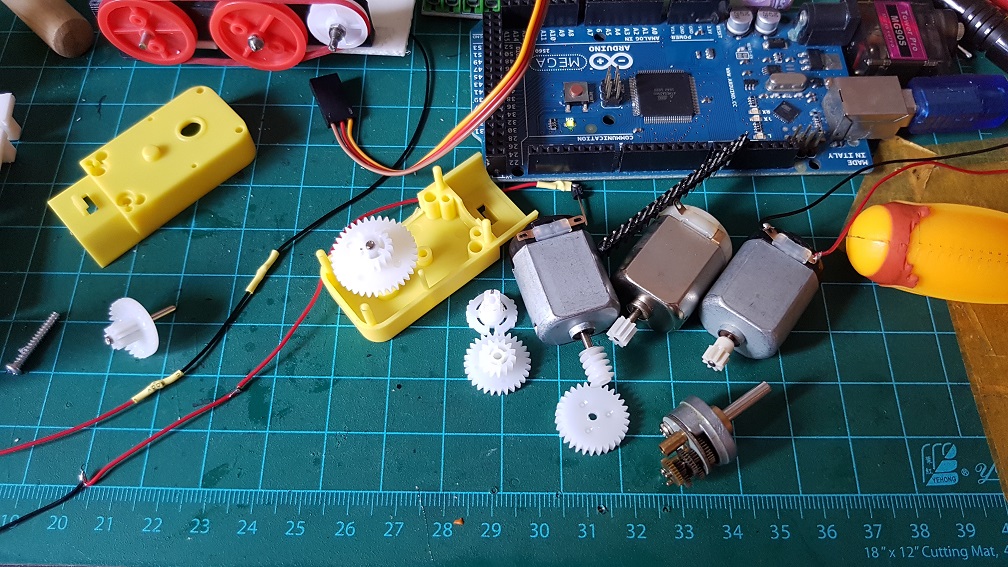
 And then I found that I have a longer DC motor with metal gears built into it and i tried to figure our if I can incorporate this gear box into my current system, which is also rather impossible as the ratio for this gear box is about 1:45. when I only need about 1:5 to 1:8. if i use this, I will have the belt driver running too slow.
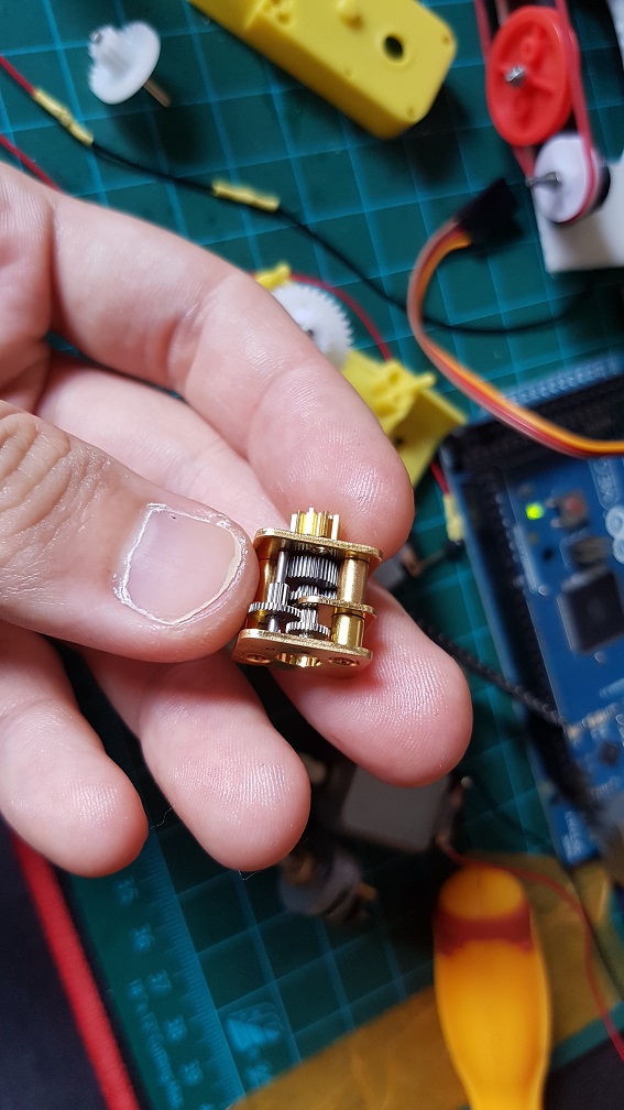 same goes for this, but this is 1:250… even slower.
 after trying out the workable speed of sound and getting stuck by removing the buttons.
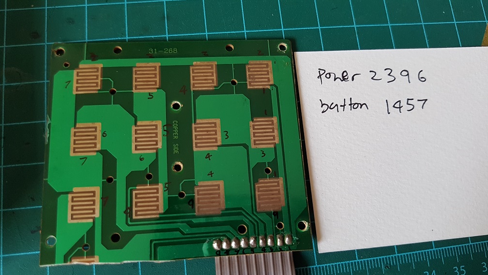 to make use of the original button on the phone, I’ve figured that the 12 buttons runs on 2 different circuit which I could simply solder these number together and make all the 12 buttons into one button, so nomatter which buttons the user pressed, it will be registered as one button pressed.
 Because I cut off the Redial button on the phone to make space for my belt driver system, I epoxyed the Redial button back to the case as there are no PCB supporting it.
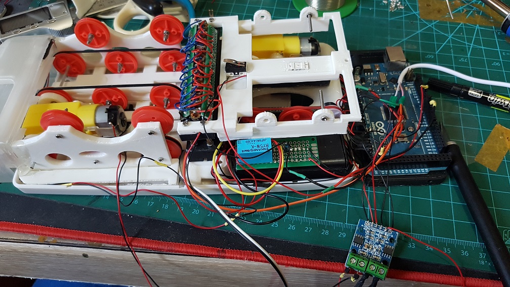
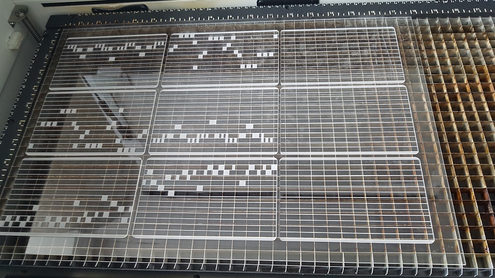 Laser raster and cut in school on 2mm acrylic.
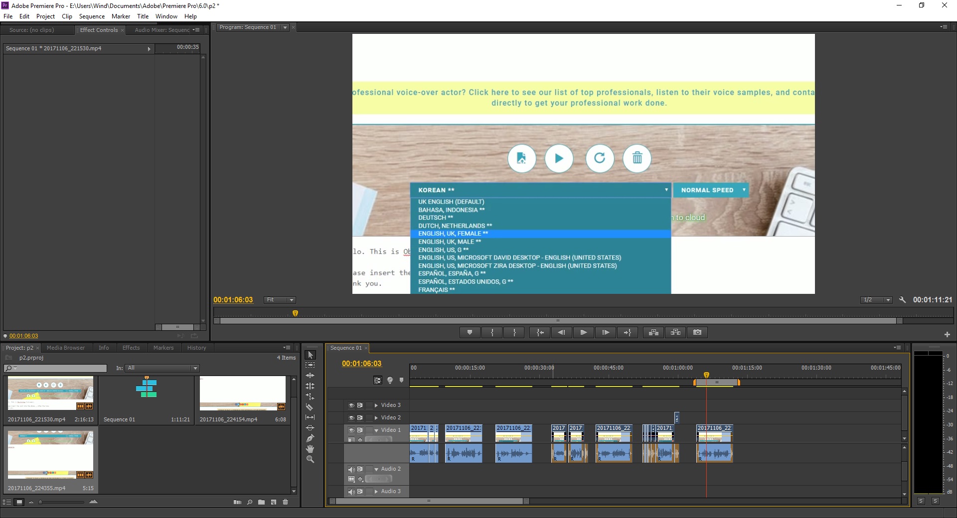 I really like the Japanese and Korean accent, its really funny!
 I am really glad that this many piece worked well together and this was the biggest challenge.. since there are so many components working together (electrical and mechanical), even if one of the parts failed, it would not work as well as it is now. So I considered myself really lucky that the parts happened to work well even when there are misalignment everywhere.
 I did some wiring afterwards.
 And after the wiring, I did power test, it could easily run 8 servos simultaneously with nothing overheating. which is a great news for me!
 This was quite the final base before I added the mount for the small backleg servo and the servo driver mount which will be attached it using screws.
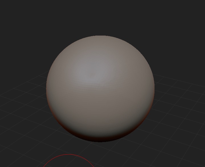


 Nothing is more satisfying in removing the support in one whole chunk(I did alot of cutting before this video so I can pluck out in one piece.)
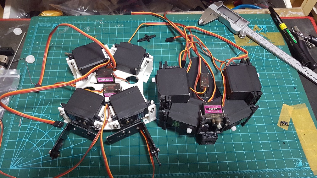

 this is the liner slider an an aluminium rod for the head system.
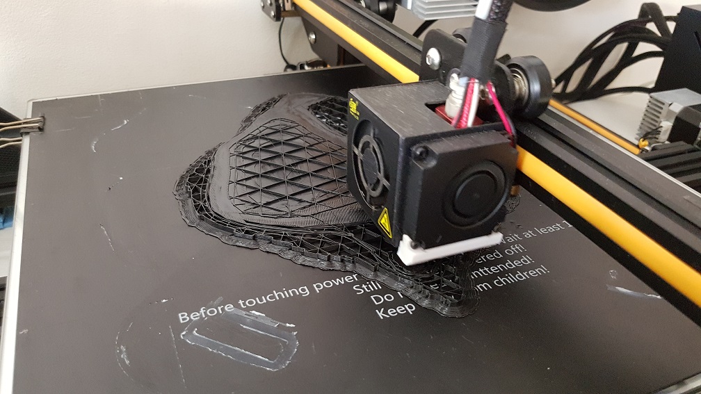

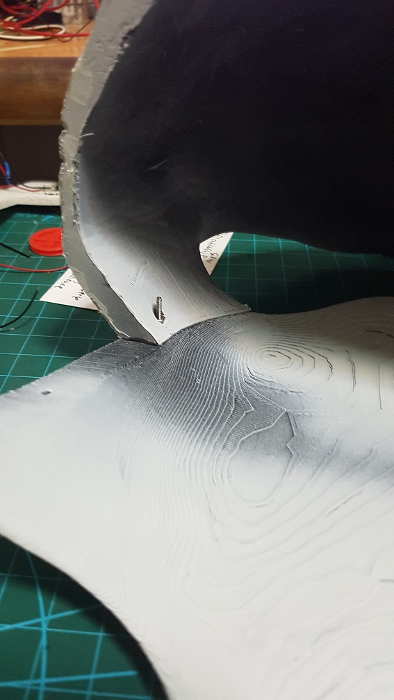
 testing out of the head slider and to mark the length I need it to move and cut.
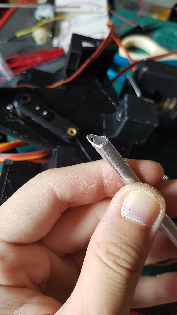
 The mechanism to slide the head that I will use after cutting the rod to almost the size I need.
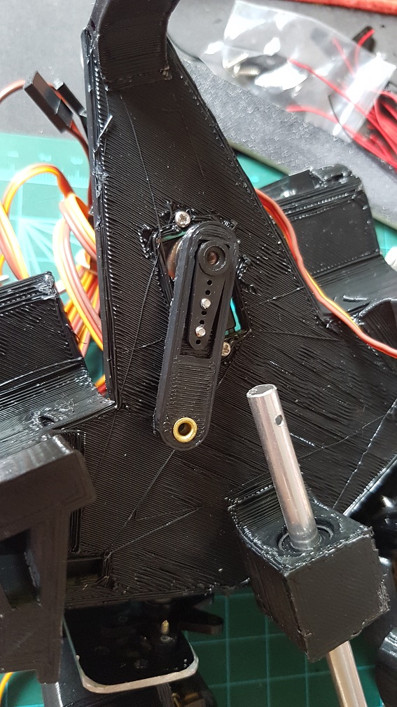
 this is the final mechanism for the head after I printed a small piece to prevent the wire from tilting too much when pushing the rod.
 the head could be push and pull out nicely even before adding the string to control the tilt of the head.
 metal rod were epoxyed into the head to tie the elastic thread to control the tile of the head.
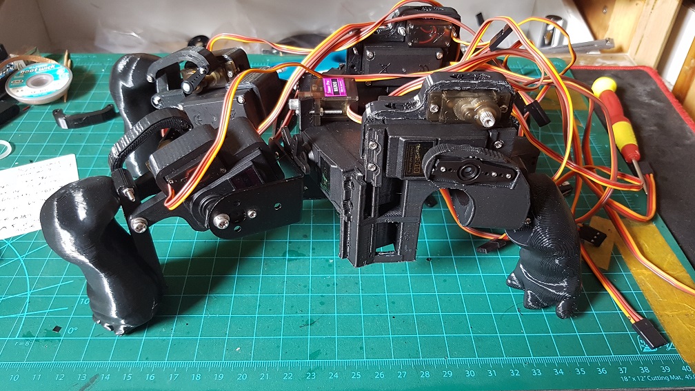
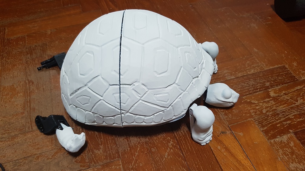
 The final test of the turtle before I finally started coding it. The head uses elastic thread because it will go forward and retract, since I dont want anything to be loose and might interfere with the shoulder servo motor, I decided to use elastic thread so that the thread wont be loose when the head is retracted.
 This is the almost completed sequence of action,the turtle’s movement is quite restricted due to the shell and the back leg is unable to push the turtle forward because of the shell’s restriction as well as the weaker servo(MG90S) which is responsible for the forward and backward thrust, while the MG966R is strong enough to lift the turtle up, so the turtle could do movements up and down but not walk.
 This was what made into my final turtle with many component being edited into the next version.


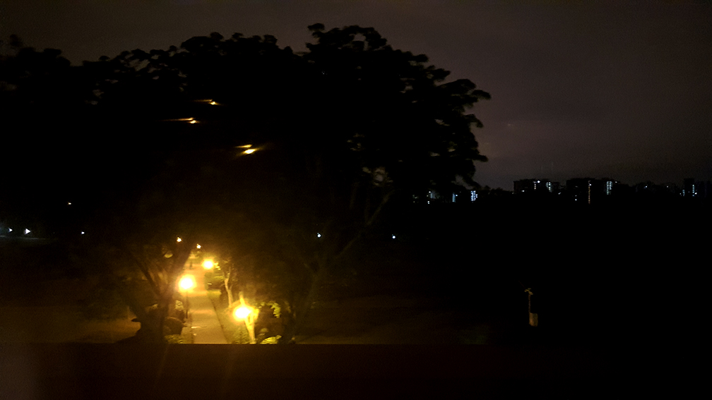
 I really like this random shot before the Stroll.
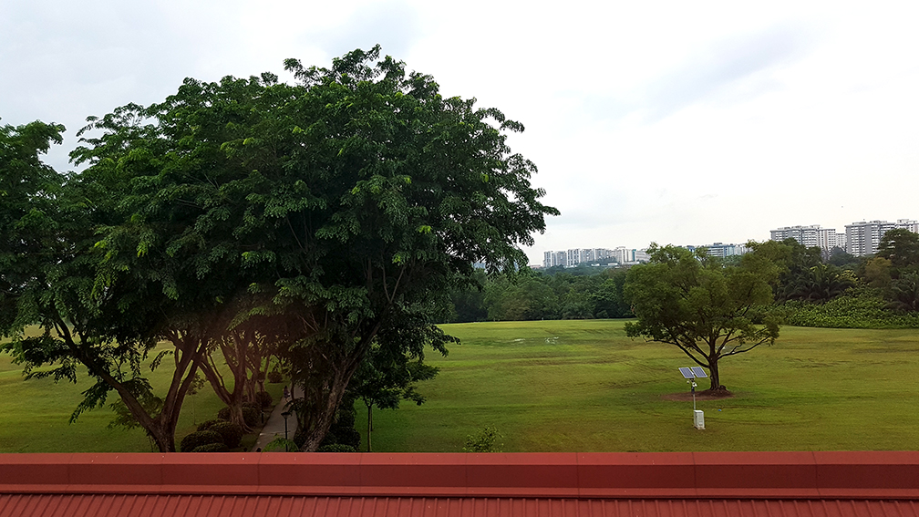
 After the stroll, when the sun finally rise.
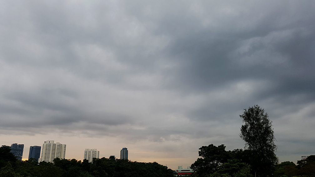 Luckily for me, right after we finished the broadcasting, it started to drizzle. And did I mentioned that we were supposed to do on Monday morning and we woke up at 5a.m. and it was raining so we postpone our stroll, it was really lucky for us that it wasn’t raining on Tuesday morning even when the weather forecast said would.