Designed by Xuedi Chen and Pedro G. C. Oliveira
Photographed By: Roy Rochlin
Model: Heidi Lee
Makeup: Rashad Taylor
Concept:
The outfit reflect the amount of data you generate when using the internet. Based on the amount of data generated, it will make parts of the outfit more transparent then the others. It creates a commentary of how transparent one is on the internet despite having things like privacy settings. On Xuedi’s website they states,
By participating in this hyper-connected society while having little to no control of my digital data production, how much of myself do I unknowingly reveal? To what degree does the aggregated metadata collected from me paint an accurate portrait of who I am as a person? What aspects of my individuality are reflected in this portrait?
The work broadcasts the artists’ concern on the wearer, exposing the wearer literally to the public view as contrast to the exposed data we have online.
Process:
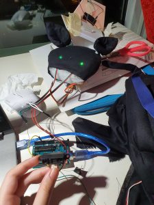
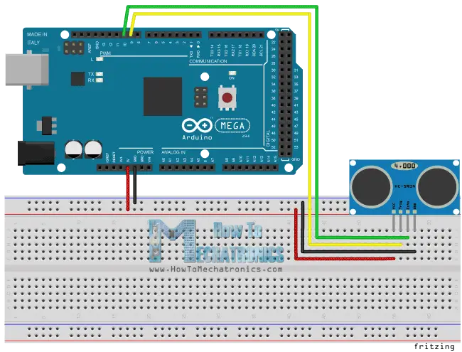
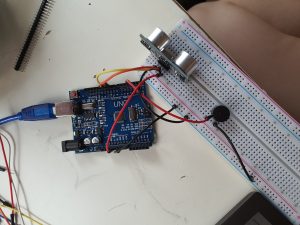
- Creation of app to connect to the outfit
- The app is used to collect the data generated from their phone at each time at every location. The data generated is sent via Bluetooth from their phone to a Bluetooth Arduino in the outfit.
(photo taken from: https://www.pedro.work/#/xpose/)
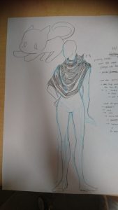
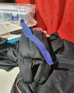
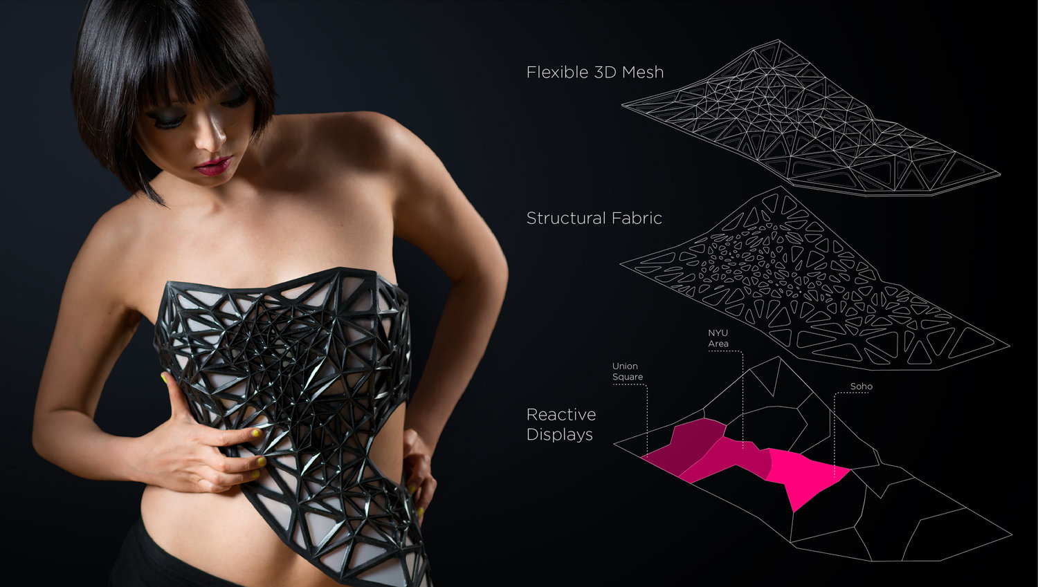
- Creation of Flexible mesh armature
- Designed geometrically to reflect areas that the artists visit often. (like Soho, NYU, Union square.
- Opacity of the dress
- Depending on the amount of data generated, the outfit would change opacity accordingly.
Materials:
According to the artists’ website, the material used for the armature of the outfit is a flexible 3D printed mesh
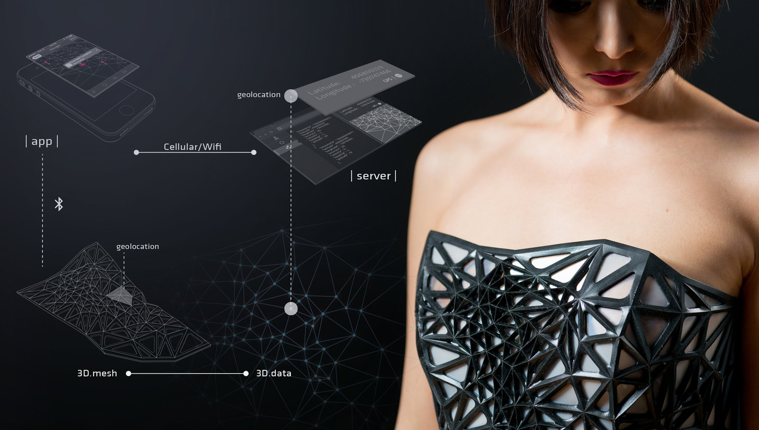
(photo taken from: https://www.pedro.work/#/xpose/)
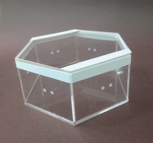
Subsequently, they also mentioned that the opacity changing material is made from electrochromic film, also the materials used to make smart windows.
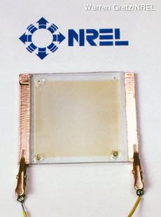

(Photos taken from: https://www.explainthatstuff.com/electrochromic-windows.html)
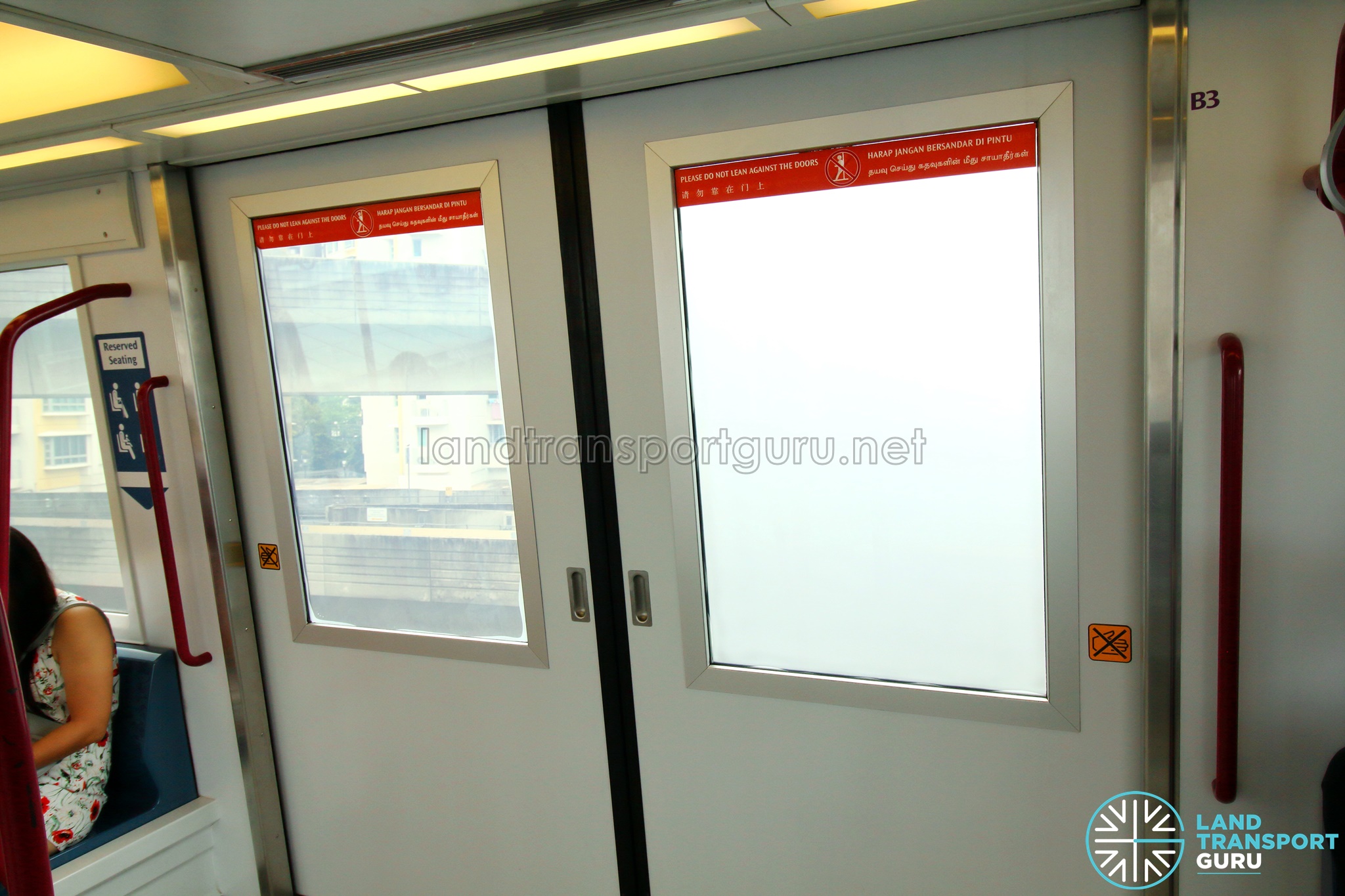
(similar to the material that is used for our LRT windows)
Electrochromic films use technology similar to an LCD display, which uses liquid crystals, under precise electronic control, to change how much light can get through. When the current is switched on, the crystals line up like opening blinds, allowing light to stream straight through; switched off, the crystals orient themselves randomly, scattering any light passing through in random directions, so making the material turn opaque.

(Photo taken from: https://www.explainthatstuff.com/electrochromic-windows.html)
References:
- http://xc-xd.com/x-pose
- https://3dprint.com/5802/x-pose-3d-printed-dress/
- https://www.explainthatstuff.com/electrochromic-windows.html
- https://www.pedro.work/#/xpose/